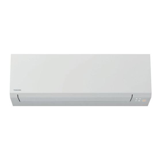
Summarization of Contents
2. SPECIFICATIONS
2-1. Specification
Details product specifications including capacity, electrical characteristics, dimensions, and piping connections.
2-2. Operation Characteristic Curve
Displays graphs illustrating compressor speed versus current draw for cooling and heating modes.
2-3. Capacity Variation ratio According to Temperature
Illustrates how cooling and heating capacity output varies in relation to ambient temperature.
3. REFRIGERANT R32
3-1. Safety During Installation/Servicing
Covers essential safety precautions for handling R32 refrigerant during installation and servicing procedures.
3-2. Refrigerant Piping Installation
Details requirements for installing refrigerant piping, including materials, joints, and processing.
3-3. Tools
3-3-1. Required Tools
Lists specialized tools needed for R32/R410A systems and general tools for installation and servicing.
3-5. Brazing of Pipes
3-5-1. Materials for Brazing
Describes suitable brazing filler materials and explains the necessity and types of flux for proper brazing.
3-5-3. Brazing
Explains the brazing method to prevent oxidation and precautions for performing brazing work safely.
4. CONSTRUCTION VIEWS
4-1. Indoor Unit
Provides detailed diagrams of the indoor unit's construction, including dimensions and component locations.
4-2. Outdoor Unit
Presents construction views and dimensions for the outdoor unit, with detail drawings.
6. SPECIFICATIONS OF ELECTRICAL PARTS
6-1. Indoor Unit
Lists electrical parts for the indoor unit with their type names and specifications.
6-2. Outdoor Unit
Lists electrical parts for the outdoor unit with their type names and specifications.
7. REFRIGERANT CYCLE DIAGRAM
7-1. Refrigerant Cycle Diagram
Shows a schematic diagram of the refrigerant flow and key components within the system.
7-2. Operation Data
Provides operational data for cooling and heating modes under specific temperature conditions.
8. CONTROL BLOCK DIAGRAM
8-1. Indoor Unit
Outlines the control logic and components within the indoor unit's microcomputer system.
8-2. Outdoor Unit (Inverter Assembly)
Details the control block diagram for the outdoor unit's inverter assembly and its functions.
9. OPERATION DESCRIPTION
9-1. Outline of Air Conditioner Control
Explains the overall control system, roles of indoor/outdoor units, and command signals.
9-2. Operation Description
Covers basic operations, cooling/heating modes, AUTO, DRY, and other specific operational functions.
9-3. Auto Restart Function
9-3-1. How to Cancel the Auto Restart Function
Describes the automatic restart feature and how to cancel it using the indoor unit's button.
9-3-2. How to Set the Auto Restart Function
Details how to set the automatic restart feature using the indoor unit's button.
9-3-3. Power Failure During Timer Operation
Explains the effect of power failure on timer operations and how to reset them.
9-4. Remote control
9-4-1. Remote control and its functions
Identifies the buttons and functions of the remote controller.
9-4-2. Operation of remote control
Explains how to use various remote control operations like weekly timer and mode settings.
9-4-3. Name and Functions of Indications on Remote Controller
Details the meaning of symbols and indicators displayed on the remote controller's LCD screen.
10. INSTALLATION PROCEDURE
10-1. Installation Diagram of Indoor and Outdoor Units
Provides a visual guide showing the placement and clearances for indoor and outdoor unit installation.
10-2. Installation
Covers general installation aspects, optional parts, accessories, and required tools for the system.
10-3. Indoor Unit
Provides detailed guidance on indoor unit installation, including placement and fixing.
10-4. Outdoor Unit
Specifies ideal locations and precautions for outdoor unit installation, considering environmental factors.
10-5. Electrical works
Explains the procedures for electrical connections, including wiring and power supply.
10-6. Others
Covers additional procedures like gas leak test, remote control setup, and test operation.
11. HOW TO DIAGNOSE THE TROUBLE
Precautions when handling the new inverter
Warns about high voltage and careful handling of the inverter circuit board during inspection.
11-1. First Confirmation
Outlines initial checks for power supply, voltage, and normal program operation before detailed diagnosis.
11-2. Primary Judgment
Describes methods for diagnosing troubles using LED indicators, remote controller, and general symptoms.
11-3. Judgment by Flashing LED of Indoor Unit
Explains how to interpret flashing LED codes on the indoor unit for self-diagnosis of protective circuits.
11-4. Self-Diagnosis by Remote Controller (Check Code)
Details how to access and interpret diagnostic check codes using the remote controller's service mode.
11-5. Judgment of Trouble by Every Symptom
Provides troubleshooting steps based on specific operational symptoms observed with the unit, covering power and fan issues.
11-5-2. Wiring Failure (Interconnecting and Serial Signal Wire)
Addresses issues related to wiring failures between indoor and outdoor units, and signal communication problems.
11-6. How to Check Simple the Main Parts
Guides on checking the functionality of key components like the pulse motor valve and sensors.
11-7. How to Diagnose Trouble in Outdoor Unit
Provides methods to diagnose troubles specifically within the outdoor unit.
11-8. How to Check Simply the Main Parts
Details methods for checking main parts, including the indoor unit's P.C. board.
11-9. How to Simply Judge Whether Outdoor Fan Motor is Good or Bad
Explains how to test the outdoor fan motor for proper operation and potential failures like mechanical lock or winding issues.
12. HOW TO REPLACE THE MAIN PARTS
12-1. Indoor Unit
Step-by-step guide for removing and replacing major internal components of the indoor unit.
12-2. Outdoor unit
Provides procedures for detaching and replacing major components of the outdoor unit.
13. EXPLODED VIEWS AND PARTS LIST
13-1. Indoor Unit
Provides an exploded view and parts list for the indoor unit components.
13-2. Indoor Unit (Part-E)
Shows an exploded view and parts list for specific indoor unit components (Part-E).
13-3. Outdoor Unit
Offers an exploded view and parts list for the outdoor unit components.
13-4. Outdoor Unit (Part-E)
Displays an exploded view and parts list for specific outdoor unit components (Part-E).


Need help?
Do you have a question about the RAS-35J2AVSG-ND and is the answer not in the manual?
Questions and answers