
Related Manuals for Hunter ET SYSTEM SMARTPORT


Summary of Contents for Hunter ET SYSTEM SMARTPORT
- Page 1 ET System Evapotranspiration Sensor and Module for Hunter Controllers with SmartPort ® Owner’s Manual and Programming Instructions...
-
Page 2: Table Of Contents
TABLE OF CONTENTS ..........................Introduction ................1 Set Time/Date ...............15 ET System Components ............3 Set Daylight Savings .............16 System Overview and ET System Operation ......3 Plant Type ..............16 Installing the ET Sensor ............4 Maturity ................17 Additional Tools and Materials ........4 Type ................17 Choose the Location ............4 Variety................17 ET Sensor Wiring ............5... -
Page 3: Introduction
This product is intended for turf and landscaping applications only, not intended for agricultural or scientific use. Use the ET System Worksheet. One is included with each ET System, and this can also be downloaded free of charge from the Hunter Industries web site (www.hunterindustries.com at the ET System product page). -
Page 5: Et System Components
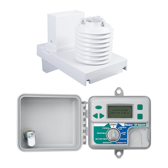
100' (33mm) two-conductor direct burial for connection to ET Sensor SySTEm OvErvIEw ANd ET SySTEm OpErATION ................. The ET System can be simply and easily installed with any Hunter The ET Module is wired into the controller’s SmartPort and creates SmartPort®-equipped irrigation controller. The System consists of the... -
Page 6: Installing The Et Sensor
ET Sensor. This wire has been specially tested for ET installations and is approved to 100’/33m max. If any other wire is to be used, Hunter recommends 2 x 18 AWG/1mm wire rated for direct burial, color-coded or otherwise marked to identify the separate conductors. -
Page 7: Et Sensor Wiring
g) Position the ET Sensor where it can be reached for occasional ser- Locate the screw terminal strip. Connect the two long conductors vice. The rain gauge should be checked and cleaned once a month (green and black) to the appropriately labeled terminals. during the warmer months, to ensure that it is free of debris. -
Page 8: Metal Fence Pole
winds in the installation area can be entered while the wiring door is External mounting in outdoor low voltage conduit removed. The factory default setting is 5 mph (8 kph). With the wiring (for the above-ground exposed portion of the wire cover removed, a DIP switch is visible allowing other prevailing run) is recommended for protection from the ele- average wind speeds to be set, according to the Table 1 (note... -
Page 9: Installing The Et Module
Turn off AC power to the irrigation controller, before connecting the ET Module to the controller! The ET System receives its power from the SmartPort connection to the Hunter controller. Do not connect the ET Module to the controller while AC power is turned on. -
Page 10: Src Or Src Plus Controller Connection
Sensor with appropriately sized butt splices or wire nuts. These two Connect the white wire from the ET Module to the terminal in the wires may be extended up to 100 ft./30m to reach the sensor. controller labeled AC2. SRC or SRC Connect the blue wire from the ET Module to the terminal in the con- troller labeled REM. -
Page 11: Remote Control Connection
Remote Control Connection ACC Controller Connection If a remote control (either Hunter ICR or SRR) receiver is to be con- The ET System is shipped with a special adapter for use with the ACC nected, connect the Orange wire (or Blue-And-White-Striped wire in series of controllers. - Page 12 Installation Plug the male pin side of the ET/ACC Adapter into the SmartPort receptacle on the ACC controller. ET connections are now made. Remove the screws holding the terminal strip cover on ET/ACC adapter. To use an ICR receiver with the ACC through the adapter, it is only necessary to plug the ICR receiver into the receptacle on the adapter, Connect the red, white, and blue wires from the ET Module (in that and issue commands normally.
-
Page 13: Test
Sensor wiring with a DC voltmeter – the voltage reading at the black and green terminals on the sensor should be between 9 to The Sensor Bypass switch on Hunter controllers will have no effect 15VDC. on the ET System, or any of its Pause modes. This switch only affects external “Clik”... -
Page 14: Programming And Operating The Et Module
Do not use harsh chemicals or abrasives, particularly on the clear plastic solar radiation lens. It is very important that this sensor be kept clean and dust-free to record sunlight accurately. The rain gauge may gather dust and debris, and should also be cleaned out every 30 days. Solar Radiation Rain Gauge Sensor... -
Page 15: Setup Overview
0.00 until the sensor has accumulated enough data to generate an according to ideal specifications. automatic ET (this may take up to one hour). Hunter recommends observing performance carefully over the first weeks of operation and adjusting the percentage to tweak system performance. -
Page 16: Controller Type
ET. Press and hold either key to accelerate the setting. ET System will not begin to water immediately, and Program A At the Controller Type dial position, select the type of Hunter control- will not be cleared until ET System decides to water. The system ler to which the ET Module is connected. -
Page 17: Set Time/Date
ACC Controllers +/- to enter the minute. The Hunter ACC controller is compatible with ET System, but setup Use the right arrow key to advance to the AM/PM setting, and use +/- is somewhat different. See installation section for use of the ET/ACC to finish the time setting. -
Page 18: Set Daylight Savings
If Daylight Savings is set to USE, the time will change forward one Plant Type hour at 2 AM on the last Sunday in March, and will change backward At the Plant Type dial position, select and customize the actual plants one hour at 2 AM on the last Sunday in October. -
Page 19: Type
Type Selects the general plant type, from a table of choices. The Type setting chooses the general category of plant, based on groups defined in WUCOLS (Water Use Classification of Landscape Species). This important setting will tell the system the plant's characteristics including the depth of the root zone, and the sensitivity of the species to watering. - Page 20 ET System built-in menu selections (samples shown are representative of each variety): TYPE Grass Shrub Ground Cover Vine Tree Perennial Desert FESCUE HIGH HIGH HIGH HIGH HIGH WATERING: WATERING: WATERING: WATERING: WATERING: Azalea Babys Tears Climbing Rose Willow, Birch Horsetail SEASONAL RYE BLUEGRASS WATERING:...
-
Page 21: Site Info
Turn the dial back to the Automatic position to save the station Determining the slope percentage: The slope is defined as the setting. amount of elevation change, or Rise, divided by Run (the measured distance), multiplied by 100. If an irrigated area rises 2 (feet or Hold down both the + and –... -
Page 22: Sun
To simplify setup, several standard types of irrigation devices are included, along with typical precipitation rates. Select the type closest Sets the average amount of sunlight for each irrigated area, according to the irrigation for the zone. to the following values: •... -
Page 23: Water Days
Water Days One informal method to determine a sample Precipitation Rate is to place catchments at intervals over the area irrigated by a single zone. The Water Days dial position sets the days of the week on which it is There are officially calibrated catchment kits, or straight-sided metal permissible to water. -
Page 24: Daily Start Time
ET System does not necessarily water on every day that has a Yes, for DAYS OK TO WATER OK to Water. These are only the days on which it is allowed to water. For further information on this, refer to the section, “How ET System INTERVAL: 01 DAYS Decides to Water”, in the System Overview near the beginning of this REMAINING: 00 DAYS... - Page 25 start whenever the plants in a zone are threatened. START: 03:00AM The default setting is WiltGard = Off. To enable WiltGard, use the NO WATER TIME: OFF arrow keys to advance to the OFF position, and use the +/- keys to WILTGARD: OFF change the setting to ON.
-
Page 26: Rain Setting
Unfinished Watering dial is turned to any other position, watering will be terminated and will not resume! With a large system and dry weather, it is possible that the No Water Day End Times and Day End settings that are too short to complete all the watering calculated for the zones. -
Page 27: Et Setup
times for the amount of measured rainfall. RAIN SHUTOFF Rain Pauses always last for 15 minutes, after which ET System will THRESHOLD: .02 IN check the sensor again. If Rain is still detected, it will begin another 15 minute pause. This will continue until the Rain has stopped, and ET System determines that watering is still required. -
Page 28: Automatic
3:00PM 15MAR06 Hunter recommends observing performance carefully over the first weeks of operation and adjusting the percentage only as a last resort DAILY ET: 0.07 IN to tweak system performance. -
Page 29: Watering History
If the ET has been set to ET SOURCE: MANUAL, the current ET will In the example, Station 1 is Soaking between Cycles 1 and 2 (of 3 total be displayed along with “MANUAL”. This shows that the ET has been Cycles), and there are 32 minutes left in the Soak period before Cycle entered manually and will not change automatically. - Page 30 Use the arrow buttons to move to the Station number, and press + or The ET System knows they did not replenish completely, and on the – to see the station histories on the selected day. next legal watering day it will try to replenish all lost moisture, includ- ing the deficit from the previous Unfinished day.
-
Page 31: View Sensor Date
substitute for a well-designed and well-maintained high efficiency ET System will automatically adjust for all natural rainfall. How- irrigation system. ever, if it begins raining before the start time, and more rain occurs after the start time, the R24 display will only show the rain which View Sensor Data has occurred after the start. -
Page 32: Troubleshooting
System. This will wipe any moisture deficits out of memory, allowing 11:15PM 04APR07 the ET watering to start over with normal soil. PRESS PLUS BUTTON TO ET System always shows the accumulated ET for the day in the dis- play, at the Automatic position. It does not show all accumulated ET RESET ET since the last watering, only the daily total. - Page 33 Waters with controller ET System must also be Off. Set ENABLE ET to NO (ET Setup position). dial in OFF position Dry or dead spots in Variation in sprinklers, spacing. Check sprinkler layout grass Check plant type, soil type, and slope settings Increase ET Adjust % gradually (by 5-10%) and monitor over the course of several weeks for improvement.
- Page 34 ET System Diagnostics Station Test Dial in Auto position Push and hold left 3 buttons (STA & left and right arrow buttons) Press and release Reset button Release left 3 buttons Station 1 should run for 1-2 minutes. View Sensor Data Dial in ET Setup position Press and hold STA button Release STA button...
- Page 35 How Settings Affect Irrigation Sand Soil Clay Longer cycles, faster evaporation More & shorter cycles, less evaporation 0%, Flat Slope 45%, Steep Fewer cycles More cycles Sprinkler Precipitation High Longer run times Shorter run times Plant Type (Kc) High Less watering More watering Lower Higher...
-
Page 36: Specifications
• Connect the equipment into an outlet on a circuit different from that to which the receiver is connected. Consult the dealer or an experienced radio/TV technician for help. Hunter Industries Incorporated • The Irrigation Innovators Internet: www.HunterIndustries.com P/N 654200...
Need help?
Do you have a question about the ET SYSTEM SMARTPORT and is the answer not in the manual?
Questions and answers