Table of Contents
Advertisement
Quick Links
General Installation, Operation and Maintenance Instructions For Aerovent Products
Throughout this manual, there are a number of HAZARD WARNINGS that must be read and adhered to in order
to prevent possible personal injury and/or damage to equipment. Two signal words "WARNING" and "CAUTION"
are used to indicate the severity of a hazard and are preceded by the safety alert symbol.
WARNING
Used when serious injury or death MAY result from misuse or failure to follow specific instructions.
CAUTION
Used when minor or moderate injury or product / equipment damage MAY result from misuse or failure to follow
specific instructions.
NOTICE
Indicates information considered important, but not hazard-related.
It is the responsibility of all personnel involved in installation, operation and maintenance to fully understand the
Warning and
Caution procedures by which hazards are to be avoided.
Aerovent Catalog 172 provides additional information on this equipment. This catalog
can be found at www.aerovent.com or by contacting your local Aerovent sales representative.
Model Nomenclature
Model
BSDDP = Wall Mounted Fan, Direct Drive
BSBP = Wall Mounted Fan, Belt Driven
E = Exhaust, S = Supply
Fan Size
Impeller Type
L1 & L2 = Level 1 & Level 2, Fabricated Steel, Fixed Pitch (5-Bladed)
B = Cast Aluminum, Adjustable Pitch (4-, 5- and 6-Bladed)
E = Cast Aluminum, Adjustable Pitch (4- and 8-Bladed)
C = Cast Aluminum, Adjustable Pitch (4- and 6-Bladed)
Z = Fabricated Steel, Fixed Pitch (5-Bladed)
Hub Designation (B Impellers Only)
No. of Blades
Impeller Blade Angle (B, C, E and Z Impellers Only)
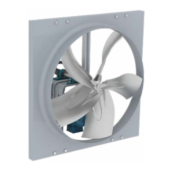
Wall Mounted Fans
Models: BSBP, BSDDP
BSBP
©2014 – 2020 Twin City Fan Companies, Ltd.
IM-172
December 2020
BSDDP
BSBP - E - 24 - B - 1 - 05 - 25
Advertisement
Table of Contents

Related Manuals for Aerovent BSDDP


Summary of Contents for Aerovent BSDDP
- Page 1 Aerovent sales representative. BSBP BSDDP Model Nomenclature BSBP - E - 24 - B - 1 - 05 - 25 Model BSDDP = Wall Mounted Fan, Direct Drive BSBP = Wall Mounted Fan, Belt Driven...
-
Page 2: Limitation Of Warranties And Claims
CONSTITUTE A VOLUNTARY WAIVER OF ANY AND ALL by misuse, neglect, improper installation, repair, SUCH WARRANTIES ARISING PURSUANT TO SUCH alteration, act of God or accident. CONTACT.) Aerovent Installation and Maintenance Manual IM-172... -
Page 3: Electrical Connection
Rotation is critical. If allowed to operate in the wrong there are several things that may cause vibration, direction, the motor will overload and burn out. such as rough handling in shipment and installation, weak foundations and alignments. Aerovent Installation and Maintenance Manual IM-172... -
Page 4: Installation
NOTE: 5 amp model shown. On 10 and 15 115V amp models, adjustment is made through 115V clearance hole in heat sink. 1140 115V 1140 115V 1140 115V 1140 115V 1725 115V 1725 115V 1725 115V Aerovent Installation and Maintenance Manual IM-172... - Page 5 Panel Installation (without accessories) — BSBP & BSDDP WALL OPENING REQUIREMENTS Wall opening size and the distance between impeller and damper are two important dimensions for fan installation. Fans mounted to the wall require a different wall opening size than those mounted in collars or wall boxes. Impeller- to-damper distance (M) is important to reduce turbulance at the damper, which may lead to premature failure, and to prevent the impeller blades from hitting the actuator on motorized damper units.
- Page 6 WALL COLLAR WITH ACCESSORIES — BSBP, BSDDP Removable Screen OSHA Motor Side Guard Panel Fan Wall Collar Backdraft Damper Weatherhood Disconnect Switch Bird Screen Damper Guard WALL BOX WITH ACCESSORIES — BSBP, BSDDP Removable Screen Panel Fan Wall Box Backdraft Damper...
- Page 7 MOUNTING FLANGE MOUNTING FLANGE BACKDRAFT DAMPER BACKDRAFT DAMPER WEATHERHOOD WEATHERHOOD REMOVABLE REMOVABLE WITH SCREEN WITH SCREEN GUARD SCREEN GUARD SCREEN FLOW FLOW OUTSIDE INSIDE INSIDE OUTSIDE SUPPORTS SUPPORTS (BY OTHERS) (BY OTHERS) Supply Exhaust Aerovent Installation and Maintenance Manual IM-172...
- Page 8 2. Make sure any undesired gaps are sealed to keep the elements from leaking into the building. Aerovent Installation and Maintenance Manual IM-172...
-
Page 9: Maintenance
Bearings must also be check every two or three months is suggested. protected from water and moisture to avoid internal 3. All motors supplied with Aerovent ventilators carry a corrosion. one-year limited warranty from date of shipment. For repairs within the warranty period, the motor must 13. -
Page 10: Bearing Replacement
1. All motors carry a one-year limited warranty from date of shipment. For repairs within the warranty period, the motor must be taken to the motor manufacturer’s authorized service dealer. Contact your representative for additional warranty details. Aerovent Installation and Maintenance Manual IM-172... - Page 11 Two-groove variable pitch sheaves must be opened Mount belts straight. Shafts must the same number of turns parallel and sheaves in alignment to prevent on both sides; otherwise, unnecessary belt wear. slippage occurs, wearing belts rapidly, Aerovent Installation and Maintenance Manual IM-172...
-
Page 12: Fan Troubleshooting Chart
It is recommended that the users and installers of this shipment familiarize themselves with AMCA Publication #201, “Fans and Systems” and publication #202, “Troubleshooting” which are published by the Air Movement and Control Association (AMCA), 30 West University Drive, Arlington Heights, Illinois 60004. www.amca.org Aerovent Installation and Maintenance Manual IM-172... -
Page 13: Dimensional Data
25 x 25 184T 30.38 4.00 14.74 19.05 33 x 33 184T 36.38 5.00 15.67 19.93 39 x 39 215T 42.38 5.50 23.59 30.00 45 x 45 254T 48.38 6.00 23.59 30.00 51 x 51 254T Aerovent Installation and Maintenance Manual IM-172... - Page 14 Dimensional Data BSBP – Belt Driven, Levels 1 & 2 2.00 C SQ. OUTSIDE D MAX D MAX A DIA. A DIA. FLOW FLOW 2.00 Exhaust Airflow Supply Airflow D MAX MAX MOTOR BSBP DAMPER FRAME C SQ. EXHAUST SUPPLY...
- Page 15 BSBP – Belt Driven, Level 3, Sizes 42-60 C SQ. OUTSIDE D MAX D MAX 2.00 A DIA. A DIA. FLOW FLOW 2.00 Exhaust Airflow Supply Airflow D MAX BSBP DAMPER C SQ. MOTOR SIZE EXHAUST SUPPLY SIZE FRAME 42.38 5.50...
- Page 16 WWW.AEROVENT.COM 5959 Trenton Lane N | Minneapolis, MN 55442 | Phone: 763-551-7500 | Fax: 763-551-7501...
Need help?
Do you have a question about the BSDDP and is the answer not in the manual?
Questions and answers