Table of Contents

Related Manuals for AERMEC TA 50


Summary of Contents for AERMEC TA 50
- Page 1 Technical Manual - Installation Technical Manual • HORIZONTAL OR VERTICAL CONFIGURATION • VERSION WITH 4-6 WATER ROW COIL • VERSION WITH R410A 4 ROWS DIRECT EXPANSION COIL • VERSION WITH EXTRACTOR 19.06 6192210_12 TRANSLATION FROM ORIGINAL...
- Page 3 Dear customer, Thank you for choosing an AERMEC product. It is the fruit of many years of experience and special design studies and has been made of the highest grade materials and with cutting edge technology. The quality level is being constantly monitored, so AERMEC products are synonymous with Safety, Quality and Reliability.
-
Page 4: Table Of Contents
INDEX GENERAL STANDARDS ..............................6 ACCESSORY COMPATIBILITY ............................9 ACCESSORY WEIGHTS..............................9 ACCESSORY COMPATIBILITY ...........................10 PERFORMANCE SPECIFICATIONS..........................12 VENTILATION CURVES ...............................13 FILTERS PRESSURE DROPS ............................21 COOLING POWER YIELDED ............................22 COOLING (4 ROWS COIL) ............................23 COOLING (6 ROWS COIL) ............................31 HEATING POWER .................................39 HEATING (4 ROWS COIL) ............................39 HEATING (6 ROWS COIL) ............................41 INSTALLATION, USE AND MAINTENANCE MANUAL ..................43 GENERAL SAFETY PRESCRIPTIONS ........................43... - Page 5 MODÈLE PLUS ACCESSOIRES: Il est interdit de faire fonctionner l’appareil avec des accessoires qui ne sont pas fournis de Aermec. MODELL + ZUBEHÖR: Falls das Gerät mit Zubehörteilen ausgerüstet wird, die nicht von Aermec geliefert werden, ist dessen Inbetriebnahme solange untersagt.
-
Page 6: General Standards
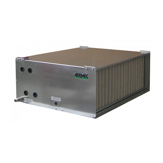
• The equipment must be installed in such a manner so as to permit • AERMEC S.p.A. decline any responsibility for any damage due to the maintenance and/or repair operations;... - Page 7 PRODUCT DESCRIPTION The TA is a compact thermoventilation unit designed to guarantee high static pressures in small or medium sized rooms. Suitable for both vertical and horizontal installations, it is available in two versions: the first features a hot or cooled water 4 or 6 rows copper-aluminium coil, the second features a direct expansion copper-aluminium coil with R410A.
- Page 8 Section made of galvanised steel sheet with F6 degree of filtration soft bag filters. For different filtering degrees, please contact the the relative room. It can be installed directly on the appliance by Aermec Sales Technical Dept. removing the flanges or on the wall. B1R 1-row water coil...
-
Page 9: Accessory Compatibility
(2) Provide time delay relays, one for each speed - Not available ACCESSORY WEIGHTS Below are the weights relating to the TA unit accessories. For more information, please contact the AERMEC S.p.a. Sales Technical Dept. Taglie DESCRIPTION intake grid GAPx... -
Page 10: Accessory Compatibility
AERMEC Sales Technical Dept. but not in the horizontal. For example: if the “SAS” accessory is provided in intake, that accessory will not be compatible with the accessory “S2Z”... - Page 11 Vertical MANDATA FLOW ASPIRAZIONE UNITA’ INTAKE UNIT GAPx GRIGLIA DI INTAKE GRID ASPIRAZIONE SSLx FTFx SASx FILTRI A BAG FILTERS DAMPER SILENCERS SERRANDA SILENZIATORI TASCHE versione 4 , 6 versione E version 4, 6 version E S2Zx PMCx oppure CAMERA DI MIXING CHAMBER 2 PLENUM PLENUM...
-
Page 12: Performance Specifications
PERFORMANCE SPECIFICATIONS Model ver. TA09 TA11 TA15 TA19 TA24 TA33 TA40 TA50 Main coil rows m³/h 1100 1100 1500 1500 1900 1900 2400 2400 3300 3300 4000 4000 5000 5000 Nominal air flow rate (1) 1111 1111 1389 1389 Useful static pressure Number of electric fans... -
Page 13: Ventilation Curves
For units with different configurations or accessories, reduce the useful static pressure with the pressure drop values of the added components. The values of these pressure drops can be found on the tables below the charts. TA 09 4R Air flow rate H Maximum speed;... - Page 14 TA 11 4R 1000 1050 1100 Air flow rate H Maximum speed; M Average speed; L Minimum speed Description Notes Accessory Air flow rate 1000 1100 Intake grid Anti-freeze damper Intake silencers Return fan Mixing chamber with 3 dampers Mixing chamber with 2 dampers Mixing chamber with 2 front dampers ∆...
- Page 15 TA 15 4R 1000 1200 1400 1600 Air flow rate H Maximum speed; M Average speed; L Minimum speed Description Notes Accessory Air flow rate 1100 1300 1500 Intake grid Anti-freeze damper Intake silencers Return fan Mixing chamber with 3 dampers Mixing chamber with 2 dampers Mixing chamber with 2 front dampers ∆...
- Page 16 TA 19 4R 1100 1300 1500 1700 1900 Air flow rate H Maximum speed; M Average speed; L Minimum speed Description Notes Accessory Air flow rate 1000 1300 1600 1900 Intake grid Anti-freeze damper Intake silencers Return fan Mixing chamber with 3 dampers Mixing chamber with 2 dampers Mixing chamber with 2 front dampers ∆...
- Page 17 TA 24 4R 1000 1200 1400 1600 1800 2000 2200 2400 Air flow rate H Maximum speed; M Average speed; L Minimum speed Description Notes Accessory Air flow rate 1200 1600 2000 2400 Intake grid Anti-freeze damper Intake silencers Return fan Mixing chamber with 3 dampers Mixing chamber with 2 dampers Mixing chamber with 2 front dampers...
- Page 18 TA 33 4R 1000 1500 2000 2500 3000 Air flow rate H Maximum speed; M Average speed; L Minimum speed Description Notes Accessory Air flow rate 1300 1700 2100 2500 2900 3300 Intake grid Anti-freeze damper Intake silencers Return fan Mixing chamber with 3 dampers Mixing chamber with 2 dampers Mixing chamber with 2 front dampers...
- Page 19 TA 40 4R 1500 2000 2500 3000 3500 4000 Air flow rate H Maximum speed; M Average speed; L Minimum speed Description Notes Accessory Air flow rate 1500 2000 2500 3000 3500 4000 Intake grid Anti-freeze damper Intake silencers Return fan Mixing chamber with 3 dampers Mixing chamber with 2 dampers Mixing chamber with 2 front dampers...
- Page 20 TA 50 4R 2500 3000 3500 4000 4500 5000 Air flow rate H Maximum speed; M Average speed; L Minimum speed Description Notes Accessory Air flow rate 2500 3000 3500 4000 4500 5000 Intake grid Anti-freeze damper Intake silencers Return fan Mixing chamber with 3 dampers Mixing chamber with 2 dampers Mixing chamber with 2 front dampers...
-
Page 21: Filters Pressure Drops
FILTERS PRESSURE DROPS The following charts determine the pressure drops of the filters with different levels of fouling. From the chart on the left, bearing the air flow rate (m³/h) in the axis of abscissae, move up from the concerned flow rate until you intersect the straight line corresponding to the unit size. At this point, tracing a straight line parallel to the axis of abscissae intersect one of the three curves shown on the right chart each representing the clogging degree of the filter as follows: curve 1: filter clean... -
Page 22: Cooling Power Yielded
OPERATING ENVIRONMENT The units are designed for installation in closed environments in ‘urban’ , non-marine atmosphere conditions that are not corrosive or dusty. The following concentrations of the air polluting factors where the unit must operate must not be exceeded under any circumstances: <0,02 ppm <0,02 ppm NO,NO... -
Page 23: Cooling (4 Rows Coil)
COOLING (4 ROWS COIL) TA 09 Tw(in) = 5°C Tw(in) = 7°C Tw(in) = 9°C Tw(in) = 11°C Tw(in) = 13°C °C °C °C 3308 2597 2643 2244 1910 2602 1424 1424 1107 1107 3288 2927 2627 2574 2039 2039... - Page 24 TA 11 Tw(in) = 5°C Tw(in) = 7°C Tw(in) = 9°C Tw(in) = 11°C Tw(in) = 13°C °C °C °C 4490 3518 3587 3040 2592 3525 1933 1933 1502 1502 4462 3966 3566 3488 2767 2767 2347 2347 1925 1925 4443 4407 3555...
- Page 25 TA 15 Tw(in) = 5°C Tw(in) = 7°C Tw(in) = 9°C Tw(in) = 11°C Tw(in) = 13°C °C °C °C 6853 5194 5475 4488 3957 5204 2950 2950 2293 2293 6811 5854 5442 5149 4223 4223 3582 3582 2937 2937 6782 6506 5426...
- Page 26 TA 19 Tw(in) = 5°C Tw(in) = 7°C Tw(in) = 9°C Tw(in) = 11°C Tw(in) = 13°C °C °C °C 9767 6953 7804 6008 5640 6966 4204 4204 3268 3268 9708 7837 7757 6893 6019 6019 5106 5106 4187 4187 9666 8709 7733...
- Page 27 TA 24 Tw(in) = 5°C Tw(in) = 7°C Tw(in) = 9°C Tw(in) = 11°C Tw(in) = 13°C °C °C °C 13627 9382 10888 8108 7868 9400 5866 5754 4559 4472 13544 10575 10822 9301 8398 8238 7124 6988 5841 5730 13486 11752 10789...
- Page 28 TA 33 Tw(in) = 5°C Tw(in) = 7°C Tw(in) = 9°C Tw(in) = 11°C Tw(in) = 13°C °C °C °C 17092 11979 13657 10352 9869 12002 7358 7347 5718 5710 16988 13502 13574 11875 10533 10518 8935 8922 7327 7316 16916 15005 13533...
- Page 29 TA 40 Tw(in) = 5°C Tw(in) = 7°C Tw(in) = 9°C Tw(in) = 11°C Tw(in) = 13°C °C °C °C 21424 15078 17119 13030 12371 15108 9223 9223 7167 7167 21294 16996 17015 14948 13203 13203 11200 11200 9184 9184 21203 18887 16963...
- Page 30 TA 50 Tw(in) = 5°C Tw(in) = 7°C Tw(in) = 9°C Tw(in) = 11°C Tw(in) = 13°C °C °C °C 25048 17843 20014 15419 14463 17877 10782 10782 8380 8380 24896 20112 19892 17688 15436 15436 13094 13094 10737 10737 24789 22350 19831...
-
Page 31: Cooling (6 Rows Coil)
COOLING (6 ROWS COIL) TA 09 Tw(in) = 5°C Tw(in) = 7°C Tw(in) = 9°C Tw(in) = 11°C Tw(in) = 13°C °C °C °C 4017 2932 3210 2534 2320 2938 1729 1729 1344 1344 3993 3305 3190 2907 2476 2476... - Page 32 TA 11 Tw(in) = 5°C Tw(in) = 7°C Tw(in) = 9°C Tw(in) = 11°C Tw(in) = 13°C °C °C °C 5277 3937 4217 3402 3047 3945 2272 2272 1766 1766 5245 4438 4191 3903 3252 3252 2759 2759 2262 2262 5223 4932 4178...
- Page 33 TA 15 Tw(in) = 5°C Tw(in) = 7°C Tw(in) = 9°C Tw(in) = 11°C Tw(in) = 13°C °C °C °C 9216 6283 7364 5429 5321 6295 3967 3853 3083 2995 9160 7082 7319 6228 5679 5516 4818 4679 3950 3837 9121 7870 7296...
- Page 34 TA 19 Tw(in) = 5°C Tw(in) = 7°C Tw(in) = 9°C Tw(in) = 11°C Tw(in) = 13°C °C °C °C 12209 8209 9755 7094 7049 8225 5256 5035 4084 3913 12135 9253 9696 8138 7524 7208 6382 6114 5233 5014 12083 10283 9666...
- Page 35 TA 24 Tw(in) = 5°C Tw(in) = 7°C Tw(in) = 9°C Tw(in) = 11°C Tw(in) = 13°C °C °C °C 16226 10722 12965 9266 9369 10743 6985 6576 5428 5111 16127 12086 12886 10630 10000 9414 8482 7986 6955 6548 16058 13431 12847...
- Page 36 TA 33 Tw(in) = 5°C Tw(in) = 7°C Tw(in) = 9°C Tw(in) = 11°C Tw(in) = 13°C °C °C °C 20715 13906 16552 12017 11961 13933 8918 8529 6930 6628 20590 15674 16452 13785 12766 12209 10829 10357 8880 8492 20502 17418 16401...
- Page 37 TA 40 Tw(in) = 5°C Tw(in) = 7°C Tw(in) = 9°C Tw(in) = 11°C Tw(in) = 13°C °C °C °C 26387 17508 21084 15130 15236 17542 11359 10738 8828 8345 26226 19734 20956 17356 16261 15372 13794 13040 11311 10692 26114 21930 20891...
- Page 38 TA 50 Tw(in) = 5°C Tw(in) = 7°C Tw(in) = 9°C Tw(in) = 11°C Tw(in) = 13°C °C °C °C 31191 20942 24923 18098 18010 20983 13427 12844 10435 9982 31002 23605 24771 20761 19222 18388 16306 15598 13370 12790 30869 26232 24696...
-
Page 39: Heating Power
Ta D.B. [°C] = Inlet water temperature with dry bulb Ph [W] = Heating power yielded entering. NB: The yield values marked in bold indicate the nominal value. HEATING (4 ROWS COIL) Ta B.S. [°C] Ta B.S. [°C] TA 09 TA 11 Tw(in) Tw(in) 11662 11157 10660... - Page 40 Ta B.S. [°C] Ta B.S. [°C] TA 24 TA 33 Tw(in) Tw(in) 36556 34973 33414 31879 30366 46984 44951 42947 40973 39029 32600 41900 35718 41396 31064 29528 45908 53205 39926 37952 34741 33158 31599 30040 28528 44651 42618 40614 38610 36666 33089...
-
Page 41: Heating (6 Rows Coil)
HEATING (6 ROWS COIL) Ta B.S. [°C] Ta B.S. [°C] TA 09 TA 11 Tw(in) Tw(in) 12783 12230 11685 11148 10619 16596 15878 15170 14473 13786 11400 14800 12490 14476 10863 10326 16216 18793 14103 13406 12149 11595 11050 10505... - Page 42 Ta B.S. [°C] Ta B.S. [°C] TA 24 TA 33 Tw(in) Tw(in) 39920 38192 36489 34812 33161 52255 49993 47764 45569 43407 35600 46600 39005 45205 33923 32246 51057 59173 44405 42209 37938 36210 34507 32805 31153 49660 47398 45170 42941 40779 36134...
-
Page 43: Installation, Use And Maintenance Manual
Installation and special maintenance must be carried out by personnel who owns the system on which the AERMEC unit is installed. He is with the necessary requisites in accordance with current regulations. - Page 44 MINIMUM OPERATIONAL SPACES All the required operational spaces must be checked before starting In particular: installation: • a space of at least 200 mm must be available at the condensation • renewal and expulsion air ducting position; drain to implement the siphon (more detailed instructions are found •...
- Page 45 CONNECTION INSTALLATION AERAULIC CONNECTIONS Hydraulic connections: condensate draining The condensate drip tray is equipped with a 1/2” -G UNI 338 threaded ATTENTION! outlet. It is prohibited to start the machine if the fan vents are not ducted or A drain system must envision a suitable siphon to: protected using an accident-prevention net.
- Page 46 The electric motors are connected on the terminal boards mounted • when connection has been made, place the external rubber gasket flush inside the unit for TA 09-11-15 and on the screw feeder of one of the with the panel to prevent seepage of air;...
-
Page 47: Repositioning Of Internal Components
REPOSITIONING OF INTERNAL COMPONENTS All TA units have been designed to facilitate the configuration and As for the hydraulic connections, proceed as follows: customisation requested by the customer as much as possible. • connect the drain pipe to the threaded stub pipe of the tray and In particular, it is possible to invert the position of the water coil plug the opposite unused stub pipe;... -
Page 48: Base Unit Connection To Accessories
BASE UNIT CONNECTION TO ACCESSORIES All base units have been designed to facilitate the configuration and consisting of screws and self-adhesive flat gasket to be applied on the contact customisation through modular accessories that fully meet the customer walls in order to prevent air leaks between one or more modules. needs. -
Page 49: Unit Maintenance
UNIT MAINTENANCE ATTENTION! FILTER MAINTENANCE (IF ANY) Wear proper personal protective equipment (PPE) to perform Cleaning the filters is fundamental to keep the air quality in the room maintenance. at a high standard. The synthetic filters mounted on TA units can be regenerated with a compressed air jet or washed with cold water. - Page 50 DISPOSAL OF UNIT The components of the TA series have been designed to run The main materials making up the units of the TA series are: continuously. The duration of some of the main components depends • galvanised steel sheets (panels, fans, condensation drip tray); on the maintenance they have received.
-
Page 51: Wiring Diagrams
WIRING DIAGRAMS TA09 E WMT05 230V 50Hz... - Page 52 TA09 E WMT06 230V 50Hz...
- Page 53 TA09 E WMT10 230V 50Hz...
- Page 54 TA 11 - 15 E TDA15 - 21 E WMT05 SIT3 SIT3 230V 50Hz...
- Page 55 TA 11 - 15 E TDA15 - 21 E WMT10 SIT3 SIT3 230V 50Hz...
- Page 56 TA19 - 24 CON WMT05 E MOTORE CMC 230V 50Hz...
- Page 57 TA19 - 24 CON WMT06 E MOTORE CMC 230V 50Hz...
- Page 58 TA19 - 24 CON WMT10 E MOTORE CMC 230V 50Hz...
- Page 59 TA33 - 50 CON WMT05 E MOTORE CMC 230V 50Hz...
- Page 60 TA33 - 50 CON WMT10 E MOTORE CMC 230V 50Hz...
-
Page 61: Dimensional Data
Unità di condizionamento - DIMENSIONAL DATA Dati dimensionali Dimensioni dell’unità (mm) Unit dimensions (mm) Dimensioni dell’unità (mm) Versione orizzontale Mod. Horizontal version TA 09 - TA 11 Mod. Versione orizzontale TA 15 1050 TA 09 - TA 11 TA 19 1050 Mod. - Page 62 Soft bag filter section «FTF» Sezione Filtri a tasche flosce « FTF » Sezione Filtri a tasche flosce « FTF » Mod. FTF1 x TA 09 - TA 11 FTF2 x TA 15 Mod. 1050 FTF1 x TA 09 - TA 11...
- Page 63 Unità di condizionamento - Recovery grid «GAP» Griglia di ripresa « GAP » Griglia di ripresa « GAP » Mod. GAP1 x TA 09 - TA 11 Mod. GAP2 x TA 15 1050 GAP1 x TA 09 - TA 11 Mod.
- Page 64 Mixing chamber 2 dampers «M2S» Camera di miscela 2 serrande « M2S » Mod. M2S1 x TA 09 - TA 11 Mod. M2S2 x TA 15 M2S1 x TA 09 - TA 11 1050 M2S2 x TA 15 1050 M2S3 x TA 19...
- Page 65 Mixing chamber 3 dampers «M3S» Camera di miscela 3 serrande « M3S » Mod. Mod. M3S1 x TA 09 - TA 11 M3S1 x TA 09 - TA 11 M3S2 x TA 15 1050 M3S2 x TA 15 1050 M3S3 x TA 19...
- Page 66 Plenum with «PMM» multiple circular flow attachments Plenum con mandate multiple circolari « PMM » D2Mod. N° Flangie Mod. No.Flanges PMM1 x TA 09 - TA 11 PMM2 x TA 15 1050 PMM1 x TA 09 - TA 11 D2Mod. N° Flangie...
- Page 67 Unità di condizionamento - 2-area damper «S2Z» Serranda 2 zone « S2Z » Serranda 2 zone « S2Z » Mod. S2Z1 x TA 09 - TA 11 Mod. Mod. S2Z2 x TA 15 1050 S2Z1 x TA 09 - TA 11...
- Page 68 Serie TA Unità di condizionamento - «SSL» Silencers Silenziatori « SSL » Mod. N° Silenziatori SSL1 x TA 09 - TA 11 SSL2 x TA 15 1050 SSL3 x TA 19 1050 SSL4 x TA 24 - TA 33 1475 Mod.
- Page 69 PX (mm) PX (mm)
- Page 72 Via Roma, 996 37040 Bevilacqua (VR) - Italia Tel. + 39 0442 633111 Fax +39 0442 93577 marketing@aermec.com www.aermec.com Aermec reserves the right to make all modification deemed necessary for improving the product at any time with any modification of technical data.
Need help?
Do you have a question about the TA 50 and is the answer not in the manual?
Questions and answers