Table of Contents
Advertisement
SERVICE MANUAL
Ver. 1.0 2016.12
• All of the units included in the HT-MT300 (SA-
MT300/SA-WMT300/Remote control) or HT-
MT301 (SA-MT301/SA-WMT301/Remote con-
trol) are required to confi rming operation of
SA-MT300/MT301. Check in advance that you
have all of the units.
Note:
Be sure to keep your PC used for service and
checking of this unit always updated with the
latest version of your anti-virus software.
In case a virus affected unit was found during
service, contact your Service Headquarters.
COMPONENT MODEL NAME
Bar Speaker (Active Speaker System)
Subwoofer (Active Subwoofer)
• Please refer to service manual separately issued for Subwoofer.
Amplifier section
US model:
POWER OUTPUT AND TOTAL HARMONIC
DISTORTION:
(FTC)
Front L + Front R:
With 4 ohms loads, both channels
driven, from 200 - 20,000 Hz; rated
15 W per channel minimum RMS
power, with no more than 1% total
harmonic distortion from 250 mW to
rated output.
POWER OUTPUT (reference)
Front L/Front R speaker blocks: 25 W
(per channel at 4 ohms, 1 kHz)
CND, AEP,UK models:
POWER OUTPUT (rated)
Front L + Front R: 20 W + 20 W
(at 4 ohms, 1 kHz, 1% THD)
POWER OUTPUT (reference)
Front L/Front R speaker blocks: 25 W
(per channel at 4 ohms, 1 kHz)
Inputs
USB
ANALOG IN
TV IN (OPTICAL)
USB section
(USB) port:
Type A (For connecting USB memory)
9-896-353-01
2016L33-1
Sony Video & Sound Products Inc.
©
2016.12
HT-MT300/MT301
HT-MT300
HT-MT301
SA-MT300
SA-MT301
SA-WMT300
SA-WMT301
SPECIFICATIONS
BLUETOOTH section
Communication system
BLUETOOTH Specification version 4.2
Output
BLUETOOTH Specification Power
Class 1
Maximum communication range
1)
Line of sight approx. 25 m
Frequency band
2.4 GHz band (2.4000 GHz -
2.4835 GHz)
Modulation method
FHSS (Freq Hopping Spread Spectrum)
2)
Compatible BLUETOOTH profiles
A2DP 1.2 (Advanced Audio Distribution
Profile)
AVRCP 1.6 (Audio Video Remote
Control Profile)
3)
Supported Codecs
4)
SBC
Transmission range (A2DP)
20 Hz - 20,000 Hz (Sampling frequency
32 kHz, 44.1 kHz, 48 kHz)
1)
The actual range will vary depending on
factors such as obstacles between
devices, magnetic fields around a
microwave oven, static electricity,
cordless phone use, reception
sensitivity, the operating system,
software applications, etc.
2)
BLUETOOTH standard profiles indicate
the purpose of BLUETOOTH
communication between devices.
3)
Codec: Audio signal compression and
conversion format
4)
Abbreviation for Subband Codec
Front L/Front R speaker block section
Speaker system
Full range speaker system, Acoustic
suspension
Speaker
40 mm × 100 mm (1 5/8 in × 4 in) cone
type
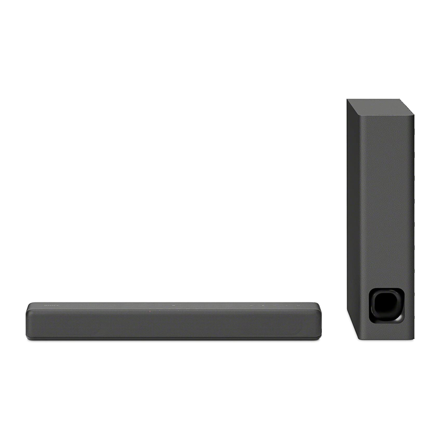
HT-MT300/MT301/SA-MT300/MT301
Photo: SA-MT300
General
Power requirements
DC 19.5 V (using the supplied AC
adapter connected to AC 100 V - 240 V,
50 Hz/60Hz power supply)
Power consumption
On: 25 W
Standby mode: 0.5 W or less
BLUETOOTH Standby mode is set to
on: 1.8 W or less*
BLUETOOTH Standby mode is set to
off: 0.5 W or less
*The system will automatically enter
Power saving mode when there is no
BLUETOOTH pairing history, even if
the BLUETOOTH standby mode is set
to on.
Dimensions* (approx.) (w/h/d)
500 mm × 54 mm × 103 mm
(19 3/4 in x 2 1/4 in x 4 1/8 in)
*Not including projection portion
Mass (approx.)
1.4 kg (3 lb 1 3/8 oz)
Compatible iPod/iPhone models
The compatible iPod/iPhone models are as
follows. Update your iPod/iPhone with the
latest software before using with the
system.
BLUETOOTH technology works with:
iPhone 7 Plus/iPhone 7/iPhone SE/iPhone
6s Plus/iPhone 6s/iPhone 6 Plus/
iPhone 6/iPhone 5s/iPhone 5c/iPhone 5
iPod touch (6th generation)/iPod touch
(5th generation)
ACTIVE SPEAKER SYSTEM
SA-MT300/MT301
US Model
Canadian Model
HT-MT300/SA-MT300
AEP Model
UK Model
Wireless transmitter section
Frequency band
2.4 GHz (2.4000 GHz - 2.4835 GHz)
Modulation method
FHSS (Freq Hopping Spread Spectrum)
What's in the Box
• Bar Speaker (1)
• Subwoofer (1)
• Remote control (1)
• R03 (size AAA) battery (2)
• Optical digital cable (1)
• AC adapter (1)
• AC power cord (mains lead) (1)
• Speaker pad for the subwoofer (4)
• Startup Guide
• Operating Instructions
Design and specifications are subject to
change without notice.
HT-MT300/MT301
SOUND BAR
SA-MT300/MT301
Advertisement
Table of Contents

Related Manuals for Sony SA-MT300


Summarization of Contents
SPECIFICATIONS
Amplifier section
Details power output, harmonic distortion, and input specifications for the amplifier.
BLUETOOTH section
Covers communication system, version, range, frequency, modulation, profiles, and codecs.
Front L/Front R speaker block section
Describes the speaker system type and cone size.
General
Provides power requirements, consumption, dimensions, and mass of the unit.
Wireless transmitter section
Specifies frequency band and modulation method for wireless transmission.
What's in the Box
Lists all included accessories and components with the product.
Compatible iPod/iPhone models
Lists compatible Apple devices for system use.
SERVICING NOTES
UNLEADED SOLDER
Discusses characteristics and usage of unleaded solder for repairs.
ADVANCE PREPARATION WHEN CONFIRMING OPERATION
States the need for all units to be present for operation checks.
NOTE OF PERFORMING THE OPERATION CHECK IN THE STATE THAT HEAT SINK IS REMOVED
Provides guidance for operation checks with the heat sink removed.
ABOUT THE PROTECTION
Explains the protection feature and troubleshooting steps.
MODEL IDENTIFICATION
Explains how to identify models using part numbers and destination codes.
DESTINATION ABBREVIATIONS
Lists and defines abbreviations for model destinations.
NFC CONNECTION CHECKING METHOD
Replacing parts for repairing that required NFC connection check
Lists components whose replacement necessitates an NFC connection check.
NFC connection checking method
Provides a step-by-step guide to perform the NFC connection check.
WIRELESS CONNECTION (LINK) WORK OF BAR SPEAKER AND SUBWOOFER
Replacing parts for repairing that required wireless connection (LINK)
Lists parts replacement that requires re-establishing wireless link.
Wireless connection (LINK) method
Step-by-step guide to re-establish wireless connection between bar speaker and subwoofer.
What to do if only bar speaker or subwoofer are brought in for repair
Instructions for handling repairs when only one unit is available.
RESETTING THE SYSTEM
RESETTING THE SYSTEM
Instructions for resetting the system to its initial state.
SPREADING OF COMPOUND
SPREADING OF COMPOUND
Instructions for applying compound when replacing IC1001 or the MAIN board.
BOND FIXED POSITION OF ELECTRICAL PARTS
BOND FIXED POSITION OF ELECTRICAL PARTS
Guidelines for fixing parts using adhesive after removal.
MALFUNCTION PREVENTION OF THE BUTTON (TOUCH PANEL SWITCH)
MALFUNCTION PREVENTION OF THE BUTTON (TOUCH PANEL SWITCH)
Precautions to prevent malfunction of touch panel buttons.
DISASSEMBLY
DISASSEMBLY FLOW
Outlines the sequence of disassembly steps.
TOP CABINET BLOCK, BOTTOM CABINET BLOCK
Detailed steps for disassembling the top and bottom cabinet sections.
SPEAKER CONNECTION CABLE
Instructions for removing and installing the speaker connection cable.
GRILLE FRAME ASSY
Steps for removing and installing the grille frame assembly.
LOUDSPEAKER (L-CH, R-CH)
Procedure for disassembling and installing the left and right loudspeakers.
LED_CHUKEI BOARD
Steps for removing and installing the LED_CHUKEI board.
TOUCH BOARD
Instructions for removing and installing the touch board.
NFC BOARD
Procedure for removing and installing the NFC board.
BLUETOOTH MODULE
Steps for removing and installing the Bluetooth module.
JACK BOARD
Instructions for removing and installing the jack board.
MAIN BOARD
Procedure for removing and installing the main board.
TEST MODE
DEMO MODE
Instructions for performing the demo mode on the unit.
RESET
Procedure to reset the main unit to its initial settings.
USB UPDATE MODE
Note about USB update mode guidance.
PANEL TEST
Key input check
Verifies the functionality of each key input on the remote control.
Model/destination/software version check
Displays model, destination, and software version information.
AMP TEST
Swap setting
Adjusts the input/output signal swap mode for different speaker configurations.
Volume setting
Controls and adjusts the volume settings for different modes.
VACS setting
Configures the Variable Acoustic Control System settings.
DRC setting
Adjusts the Dynamic Range Compression settings.
GAIN adjust
Allows adjustment of audio gain levels for various channels.
Vibration test
Performs a test for system vibrations.
L/R channel toggle
Switches the audio output between L/R channels or normal stereo.
TROUBLESHOOTING
Protection mode is occurs after turning the power on
Troubleshooting steps for when the protection mode is activated upon power-on.
The sound is not outputted
Diagnostic steps for issues with no sound output.
Power is not turned on
Troubleshooting steps for when the unit fails to power on.
USB cannot be detected
Diagnostic steps for issues where the USB device is not recognized.
DIAGRAMS
BLOCK DIAGRAM - MAIN Section -
A block diagram illustrating the main section of the system.
BLOCK DIAGRAM - PANEL/POWER SUPPLY Section -
A block diagram of the panel and power supply sections.
Circuit Boards Location
Shows the physical locations of various circuit boards within the unit.
IC Block Diagram
Provides an IC block diagram for the Touch Board.
PRINTED WIRING BOARD - MAIN Board (Side A)
Detailed view of the Main Board's (Side A) printed wiring.
PRINTED WIRING BOARD - MAIN Board (Side B)
Detailed view of the Main Board's (Side B) printed wiring.
PRINTED WIRING BOARD - TOUCH Board
Detailed view of the Touch Board's printed wiring.
SCHEMATIC DIAGRAM - TOUCH Board
Schematic diagram for the Touch Board.
PRINTED WIRING BOARD - LED_CHUKEI Board
Detailed view of the LED_CHUKEI Board's printed wiring.
SCHEMATIC DIAGRAM - LED_CHUKEI Board
Schematic diagram for the LED_CHUKEI Board.
PRINTED WIRING BOARD - JACK Board
Detailed view of the JACK Board's printed wiring.
SCHEMATIC DIAGRAM - JACK Board
Schematic diagram for the JACK Board.
EXPLODED VIEWS
FOOT SECTION
Exploded view of the foot section components and assembly.
TOP CABINET SECTION
Exploded view of the top cabinet components and assembly.
BOTTOM CABINET SECTION
Exploded view of the bottom cabinet components and assembly.
ELECTRICAL PARTS LIST
MAIN BOARD
List of electrical parts for the MAIN board.
JACK BOARD
List of electrical parts for the JACK board.
IC
List of integrated circuits used in the system.
NFC BOARD
List of parts for the NFC board.
MISCELLANEOUS
BLUETOOTH MODULE
Lists the Bluetooth module and related wire kits.
ACCESSORIES
MANUALS AND CABLES
Lists all included manuals, AC adapters, and cables.
Need help?
Do you have a question about the SA-MT300 and is the answer not in the manual?
Questions and answers