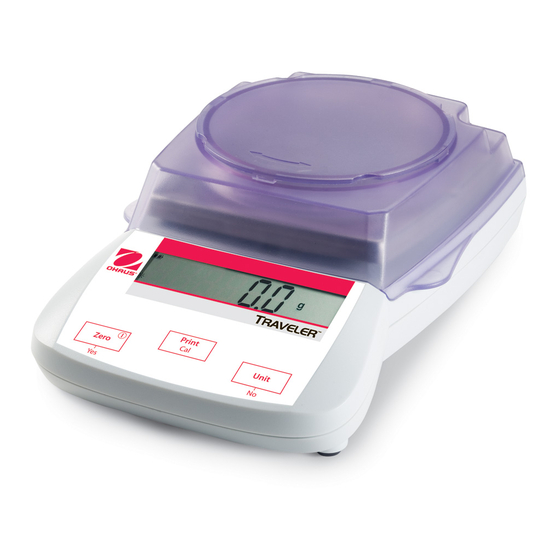
Summarization of Contents
Chapter 1 Getting Started
1.1 Introduction
Overview of manual contents, including five chapters and appendices.
1.2 Service Facilities
Requirements for the service area, including temperature control and cleanliness.
1.3 Tools and Test Equipment Required
Lists common hand tools and specifies RS232 interface for reconfiguration.
1.4 Specifications
Details technical specifications for TA, TAJ, TAG, and SE models.
1.5 Scale Operation
Basic operation of the scale, including power connection, battery use, and auto-off.
1.5.1 Overview of the Controls
Illustrates and describes displays for different Traveler series and details control functions.
1.5.2 Overview of the Display Indicators
Explains the meaning of various indicators on the Traveler LCD display.
1.5.3 Power ON
Procedure for turning the scale ON, including warm-up and calibration.
1.5.4 Power OFF
Procedure for turning the scale OFF by pressing and holding the On-Zero/Off button.
1.5.5 Menu Setup
Describes how programmable features are accessed through menus via control switches.
1.5.6 Menu Structure
Presents the menu structure and default settings for scale configuration.
1.6 Connecting the RS232 Interface
Instructions for connecting the optional RS232 interface for PC communication.
1.6.1 Hardware Setup
Steps for physically connecting the RS232 interface and cable.
1.6.2 RS232 Commands
Explains ASCII format communication and lists valid commands for the scale.
Chapter 2 Troubleshooting
2.2 Diagnostic Guide
Guide to help locate problems quickly by listing symptoms, causes, and remedies.
Chapter 3 Maintenance Procedures
3.1 Preventive Maintenance
Guidelines for routine care, cleaning, and handling to ensure scale longevity.
3.3 Replacing the Load Cell
Step-by-step instructions for removing and installing a new load cell.
3.4 Replacing the Printed Circuit Board and Display
Procedure for replacing the main PCB and LCD display assembly.
3.5 Replacing the Auxiliary Display's Printed Circuit Board
Instructions for replacing the PCB of the optional auxiliary display.
3.6 Setting/Removing Legal-For-Trade (Only in TAG and SE models)
Procedure for setting LFT mode, including calibration and lock tab.
3.7 Replacing the Function Label
Instructions for removing the old and applying a new function label.
Chapter 4 Testing
4.2 Operational Test
Procedure to verify basic scale functionality and power connection.
4.3 Segment Display Test
Procedure to verify all segments of the LCD display are functioning correctly.
4.4 Performance Tests
Tests to determine accurate performance against specifications, including repeatability and linearity.
4.4.1 Repeatability Test
Procedure to measure the scale's consistency by taking multiple readings with the same mass.
4.4.2 Off-Center Load Test
Tests how weight placement on the pan affects readings by checking off-center loads.
4.4.3 Adjusting Off Center Load
Procedure for filing the beam to correct off-center load errors.
4.4.4 Linearity Test
Determines the scale's linearity across its operating range using specific test masses.
Chapter 5 Parts Lists & Diagrams
5.1 Traveler Scales with Square Draft Shield: Housing & Parts
Exploded view and parts list for Traveler scales with a square draft shield.
5.2 Traveler Scales with Round Draft Shield: Housing & Parts
Exploded view and parts list for Traveler scales with a round draft shield.
5.3 Traveler Scales with No Draft Shield: Housing & Parts
Exploded view and parts list for Traveler scales without a draft shield.
Appendix A Standard Calibration
A.1 Calibration
Procedure for standard calibration before use and after service.
Appendix B The Service Menu
B.1 Entering the Service Menu
Procedure to access the Service Menu by pressing specific buttons.
B.2 Ramp
Explains the Ramp display, its function, and expected values.
B.3 Linear Calibration
Step-by-step guide for performing linear calibration through the service menu.
B.4 Span Calibration
Procedure for performing span calibration via the service menu.
Appendix C Software Service Tool Instructions
C.1 Hardware and Software Setup
Steps to set up the RS232 interface, software, and computer connection.
C.2 Configuring the Scale (after replacing the PCB or Load Cell)
Procedure to reconfigure scale parameters using the service tool after component replacement.


Need help?
Do you have a question about the Traveler SE602 and is the answer not in the manual?
Questions and answers