Table of Contents
Advertisement
SERVICE MANUAL
Ver. 1.2 2010.03
• HCD-DZ280/DZ680/HDZ284/HDZ485 are the amplifi er, DVD/CD
and tuner section in DAV-DZ280/DZ680/HDZ284/HDZ485.
This system incorporates with Dolby* Digital and Dolby Pro
Logic (II) adaptive matrix surround decoder and the DTS** Digital
Surround System.
* Manufactured under license from Dolby Laboratories.
Dolby, Pro Logic, and the double-D symbol are trademarks of
Dolby Laboratories.
** Manufactured under license under U.S. Patent #'s:
5,451,942; 5,956,674; 5,974,380; 5,978,762; 6,487,535 & other
U.S. and worldwide patents issued & pending. DTS and DTS
Digital Surround are registered trademarks and the DTS logos
and Symbol are trademarks of DTS, Inc. © 1996-2008 DTS,
Inc. All Rights Reserved.
Amplifi er Section
Stereo mode (rated)
108 W + 108 W (at 3 ohms,
1 kHz, 1% THD)
DZ280/DZ680/HDZ284:
Surround mode (reference) RMS output power
FL/FR/C/SL/SR*: 142
watts (per channel at 3
ohms, 1 kHz, 10% THD)
Subwoofer*: 140 watts (at
3 ohms, 80 Hz, 10% THD)
HDZ485:
Surround mode (reference) RMS output power
FL/FR/C/SL/SR*: 144
watts (per channel at 3
ohms, 1 kHz, 10% THD)
Subwoofer*: 280 watts (at
1.5 ohms, 80 Hz, 10% THD)
* Depending on the decoding mode settings and the
source, there may be no sound output.
Inputs (Analog) (DZ280/DZ680)
TV (AUDIO IN)
Sensitivity: 450/250 mV
AUDIO IN
Sensitivity: 250/125 mV
Inputs (Digital) (DZ680/HDZ284/HDZ485)
TV/VIDEO (COAXIAL IN/OPTICAL IN)
Impedance: 75 ohms/-
Input Stream: Dolby
Digital 5.1ch/DTS 5.1ch/
Linear PCM 2ch
(Sampling Frequency: less
than 48 kHz)
Sony Corporation
9-889-391-03
2010C04-1
Audio&Video Business Group
©
2010.03
Published by Sony Techno Create Corporation
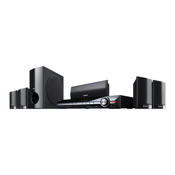
Photo: HCD-HDZ284
Model Name Using Similar Mechanism
Mechanism Type
Optical Pick-up Name
SPECIFICATIONS
Inputs (Analog) (HDZ284/HDZ485)
TV/VIDEO (AUDIO IN) Sensitivity: 450/250 mV
AUDIO IN
Sensitivity: 250/125 mV
Outputs (Analog)
Phones
Accepts low- and high-
impedance headphones.
Super Audio CD/DVD System
Laser Diode Properties
Emission Duration:
Continuous
Laser Output: Less than
44.6μW
* This output is the value measurement at a distance
of 200mm from the objective lens surface on the
Optical Pick-up Block with 7mm aperture.
Signal format system
HDZ284/HDZ485:
NTSC
DZ280/DZ680:
NTSC/PAL
USB Section (DZ280/DZ680)
(USB) port:
Maximum current:
500 mA
Tuner Section
System
PLL quartz-locked digital
synthesizer
FM Tuner section
Tuning range
Canadian, PX models:
87.5 MHz - 108.0 MHz
(100 kHz step)
HCD-DZ280/DZ680/
HDZ284/HDZ485
Canadian Model
HCD-HDZ284/HDZ485
HCD-DZ260/DZ270/HDZ278
CDM85-DVBU102
KHM-313CAA
Other models:
Antenna (aerial)
Antenna (aerial) terminals 75 ohms, unbalanced
Intermediate frequency
Video Section (DZ280/DZ680)
Outputs
Video Section (HDZ284/HDZ485)
Outputs
– Continued on next page –
DVD RECEIVER
AEP Model
UK Model
HCD-DZ280/DZ680
PX Model
HCD-HDZ485
87.5 MHz - 108.0 MHz
(50 kHz step)
FM wire antenna (aerial)
10.7 MHz
VIDEO: 1 Vp-p 75 ohms
R/G/B: 0.7 Vp-p 75 ohms
HDMI OUT: Type A (19
pin)
VIDEO: 1 Vp-p 75 ohms
COMPONENT:
Y: 1 Vp-p 75 ohms
P
/C
, P
/C
: 0.7 Vp-p
B
B
R
R
75 ohms
HDMI OUT: Type A (19
pin)
Advertisement
Table of Contents

Related Manuals for Sony HCD-HDZ485


Summarization of Contents
Servicing Notes
Handling Optical Components Safely
Precautions for handling sensitive optical components and checking laser.
Disc Tray Lock and Transport Procedures
Function to lock the disc tray and mode for transport.
Disassembly Procedures
Case and Front Panel Disassembly
Procedures for removing the outer case and front panel.
Internal Board Disassembly
Procedures for removing power, USB, main, speaker, and I/O boards.
Optical Pick-up Removal Procedure
Procedure for removing the optical pick-up unit.
Test Modes
Cold Reset and DVD Ship Mode
Procedures for system reset and returning to customer.
Panel Test Modes (Display, Version, FL)
Tests for display, version, and FL patterns.
IOP Measurement and Test Mode Entry
Procedures to enter test mode and perform IOP measurements.
Electrical Adjustments
FM Tune Level Check Procedure
Procedure to check the FM tuner signal reception level.
Diagrams
RF and Video Signal Block Diagrams
Block diagrams illustrating RF and video signal paths.
Audio, Amplifier, Power Block Diagrams
Block diagrams for audio, amplifier, and power supply sections.
Exploded Views
Overall Unit Exploded View
Exploded view of the unit's overall assembly and parts.
Electrical Parts List
Capacitors and Resistors List
List of capacitors and resistors with part numbers.
ICs and Transistors List
List of ICs and transistors with part numbers.
Connectors, Diodes, and Jacks List
List of connectors, diodes, and jacks with part numbers.
Need help?
Do you have a question about the HCD-HDZ485 and is the answer not in the manual?
Questions and answers