Table of Contents
Advertisement
The Olympus Series is NOT designed for amateur installation.
Please read this manual carefully before installation and keep it for future reference.
Installation Manual
Olympus Series
Single (Hyper Heat & E Star) & Multi-Zone Models
Due to updates and constantly improving performance, the information and instructions
within this manual are subject to change without notice. Please visit
www.mrcool.com/documentation to ensure you have the latest version of this manual.
The Olympus Series is NOT designed for amateur installation.
Please read this manual carefully before installation and keep it for future reference.
Installation SHOULD be performed by an authorized technician.
Version Date: 3-01-21
Installation SHOULD be performed by an authorized technician.
Advertisement
Table of Contents

Related Manuals for MrCool MULTI3-27HP230V1


Summarization of Contents
Safety Precautions
Read Before Installation
Instructions to read before proceeding with installation.
WARNING
Crucial warnings about potential death or serious injury.
CAUTION
Warnings about potential personal injury, damage, or property damage.
Note about Flourinated Gases
Information regarding the handling and properties of flourinated gases.
Accessories
Part List and Quantity
Details of included parts with their quantities and visual representations.
Overview
Indoor Unit Components
Identifies key parts and connections of the indoor unit.
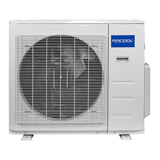
Outdoor Unit Components
Identifies key parts and connections of the outdoor unit.
Note on Illustrations
Clarification that illustrations are for explanatory purposes and may vary.
Multi-Zone System Diagrams
Illustrates multi-zone systems with wall-mounted, ceiling-ducted, and cassette indoor units.
Overview - Specifications
Table 2.1: Unit Specifications
Details operational parameters like voltage, stop time, and fluctuation.
Table 2.2: Piping Specifications
Lists maximum pipe lengths and height differences for various zone configurations.
Fig. 2.5: Max Height Difference
Diagram illustrating maximum allowable height differences between units.
Indoor Unit Installation
Installation Instructions - Indoor Unit
General guidance for indoor unit installation.
PRIOR TO INSTALLATION
Actions to take before starting the indoor unit installation.
Step 1: Select installation location
Guidelines for choosing the optimal location for the indoor unit.
Proper installation locations meet the following standards
Criteria for selecting suitable installation sites for the indoor unit.
DO NOT install unit in the following locations
Prohibited locations for indoor unit installation to ensure safety and performance.
NOTE ABOUT WALL HOLE
Advice on considering wall hole placement for piping.
Mounting Plate and Wall Hole Procedures
Instructions for attaching the mounting plate and drilling the wall hole.
Refrigerant Piping Preparation
Steps to prepare the refrigerant pipes before passing them through the wall.
Connect Drain Hose
Instructions for connecting and routing the drain hose for proper drainage.
Electrical Work Regulations
Essential safety regulations and warnings before performing electrical work.
Connect Signal Cable
Instructions for connecting the signal cable between units.
Wrap Piping and Cables
Instructions for bundling and insulating refrigerant pipes, drain hose, and signal cable.
Mount Indoor Unit
Steps for physically mounting the indoor unit onto the wall plate.
Outdoor Unit Installation
Installation Instructions - Outdoor Unit
General guidance for outdoor unit installation.
Step 1: Select installation location
Criteria for selecting an appropriate location for the outdoor unit.
Proper installation locations meet the following standards
Standards for choosing a suitable outdoor installation site.
SPECIAL CONSIDERATIONS FOR EXTREME WEATHER
Advice for installing the unit in environments with heavy wind or precipitation.
DO NOT install unit in the following locations
Prohibited locations for outdoor unit installation.
Installation Space Requirements
Diagram showing required clearances for outdoor unit installation.
Cold Climate Drain Hose Setup
Specific advice for drain hose setup in cold climate conditions and drain joint installation.
Anchor Outdoor Unit
Procedures for anchoring the outdoor unit to the ground or bracket, including unit dimensions.
Wall-Mounted Installation Details
Details for wall-mounted units, vibration reduction, 24K unit selection, and pipe size.
Step 4: Connect signal and power cables
Instructions for connecting signal and power cables, including regulations and warnings.
Wiring Diagram
CAUTION
Caution regarding correct terminal connections for power and communication cables.
2-Zone Models Wiring
Wiring diagram for 2-zone multi-zone systems.
3-Zone Models Wiring
Wiring diagram for 3-zone multi-zone systems.
4-Zone Models Wiring
Wiring diagram for 4-zone multi-zone systems.
5-Zone Models Wiring
Wiring diagram for 5-zone multi-zone systems.
Refrigerant Piping Connection
Pipe Length and Drop Height Specifications
Specifications for maximum refrigerant pipe length and drop height per unit model.
Step 1: Cut pipes
Instructions for cutting refrigerant pipes to the correct length and angle.
Pipe Deformation Warning
Warning against deforming pipes during cutting to maintain heating efficiency.
Step 2: Remove burrs
Procedure for removing burrs from cut pipe ends to ensure airtight seals.
Step 3: Flare pipe ends
Instructions for flaring pipe ends to create an airtight seal, including dimensions and tools.
Step 4: Connect pipes
Instructions for connecting refrigerant pipes, including bend radius and torque requirements.
Connecting Piping to Indoor Unit
Steps for connecting refrigerant pipes to the indoor unit.
Connecting Piping to Outdoor Unit
Steps for connecting refrigerant pipes to the outdoor unit.
Air Evacuation
Preparations and Precautions
Safety and preparation guidelines for air evacuation, including equipment.
BEFORE PERFORMING EVACUATION
Checklist of critical items to verify before starting the air evacuation process.
Evacuation Instructions
Step-by-step guide for performing air evacuation using a vacuum pump and manifold gauge.
Valve Stem Operation Caution
Cautionary note on gently operating valve stems to prevent damage.
Note on Adding Refrigerant
Guidance on calculating additional refrigerant charge based on pipe length and system type.
Refrigerant Mixing Caution
Warning not to mix different types of refrigerants.
System Leak Checks
Electrical Safety Checks
Verifying electrical wiring safety, grounding, and leakage during test run.
WARNING – RISK OF ELECTRIC SHOCK
Critical warning about electrical shock hazards and the necessity of a licensed electrician.
Gas Leak Checks
Methods for checking for refrigerant leaks using soap/water or a leak detector.
Self Correction Function (Multi-Zone Models Only)
Describes a self-check function for wiring errors in multi-zone units and how to activate it.
Test Run
Before Test Run
Prerequisites and checks required before performing the test run.
Test Run Instructions
Step-by-step guide for performing the test run and checks to perform.
Double-Check Pipe Connections
Re-checking pipe connections for leaks during operation.
Testing in Low Ambient Temperatures
Alternative method for testing the COOL function in low ambient temperatures.
EU Disposal Guidelines
Disposal Options
Various options for disposing of the appliance according to regulations.
Special Notice
Environmental warning regarding the health and ecological impact of improper disposal.
Need help?
Do you have a question about the MULTI3-27HP230V1 and is the answer not in the manual?
Questions and answers