Table of Contents
Advertisement
■
This manual is common to all the models regardless of suffixes of the Model No.
・K: Black model
・W: White model
■
Points of difference between the RZ370/RW330 series
・Contrast ratio 10 000:1 → 20 000:1
・Added "EDGE BLENDING" function
・Added "BRIGHTNESS CONTROL" function
・Equipped with "3D SYNC" terminal and added "3D projection" function
(VESA standard IR system,DLP Link system)
・Available in portrait setting
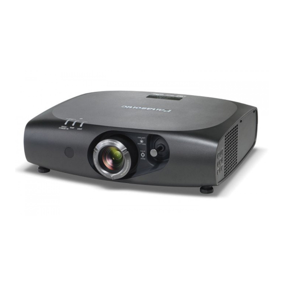
1-chip DLP Based Projector
PT-RZ470U
Model No.
PT-RZ470E
PT-RZ470EA
PT-RW430U
PT-RW430E
PT-RW430EA
© Panasonic Corporation 2013. Unauthorized
copying and distribution is a violation of law.
ORDER NO. VED1302461CE
D10
Rev.-2 (2018-01)
Advertisement
Chapters
Table of Contents
Troubleshooting

Related Manuals for Panasonic PT-RW430 Series


Summarization of Contents
Safety and Regulatory Compliance
General Safety and Handling Precautions
Covers laser radiation, lithium battery handling, lead-free solder, and general safety warnings.
Regulatory and Laser Hazard Information
Details FCC compliance and laser radiation hazards with necessary precautions.
Projector Specifications and Interfaces
Technical Specifications
Details model, power, performance, optical, and signal specifications.
Terminal Interfaces and Physical Specs
Explains physical interfaces, ports, dimensions, weight, and environmental requirements.
Operation and Service Information
Projector Anatomy and Controls
Identifies projector parts, control panel, terminals, and remote control functions.
OSD Menu Navigation
Guide to navigating main and sub-menus for Picture, Position, Advanced, Setup, and Security settings.
Service Mode Operations
Procedures for entering/exiting service mode, self-checks, calibration, and menu adjustments.
Software Update Procedures
Instructions for updating projector software via LAN or Serial connections.
Troubleshooting and Maintenance
Troubleshooting Common Issues
Covers optical block overview, shutdown system, log acquisition, error codes, and specific fault diagnosis.
Disassembly and Component Replacement
Guides on parts location, disassembly steps, and removal of major assemblies like boards, optical block, and light sources.
Adjustment Procedures
Details on lighting area, lens tilt, EEPROM transfer, airflow sensor calibration, and light source adjustments.
Schematic and Board Diagrams
Provides block diagrams, interconnection diagrams, schematics, and PCB layouts for detailed analysis.
Need help?
Do you have a question about the PT-RW430 Series and is the answer not in the manual?
Questions and answers