
Related Manuals for Teknic SC4-HUB


Summarization of Contents
Quick Start Guide
About ClearPath-SC
Introduces the ClearPath-SC system and its capabilities for servo control.
Who Should Use ClearPath-SC Motors?
Guides users on suitability of ClearPath-SC based on programming skills and project needs.
Please Read This Important Warning!
Crucial safety advisory for handling powerful motion control equipment.
Description of System Components
System Diagram
Visual representation of the ClearPath-SC system's interconnected components and data flow.
SC4-HUB
Details the SC Hub's role in connecting PC, I/O, and motors, and system expansion capabilities.
DC Bus Power Supply
Explains the function of the DC Bus Power Supply for ClearPath-SC motors.
POWER4-HUB
Describes the Power4-Hub's function in distributing power and providing backup logic power.
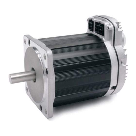
Parts of a ClearPath-SC Motor
Illustrates and names the key components and connectors of a ClearPath-SC motor.
System Setup
1. Install ClearView Software
Step-by-step instructions for downloading and installing the ClearView configuration software.
3. Connect ClearPath-SC System Components
24 Volt Logic Power Supply
Specifies the requirement and sizing considerations for a 24VDC logic power supply for system operation.
System Hookup Diagram (With a Power Hub)
ClearPath-SC Hookup Diagram (for systems with a Power Hub)
Provides a visual guide for wiring a ClearPath-SC system that includes a Power Hub.
System Hookup Diagram (Without Power Hub)
ClearPath-SC Hookup Diagram (for systems without a Power Hub)
Illustrates the wiring connections for a ClearPath-SC system that does not use a Power Hub.
5. Establish Communication (USB or RS-232 / Serial)
USB Communication
Steps for connecting and establishing communication using a USB cable with ClearView.
Setting the USB COM Port Manually
Procedure to manually configure the COM port in Device Manager if auto-detection fails.
Safety Warnings
Personal Safety Warnings
Emphasizes precautions related to personal safety when working with motion control equipment.
CE Compliance Warnings
Notes regarding CE compliance and system designer responsibilities for safety.
Introduction
What is ClearPath-SC?
Defines ClearPath-SC as an integrated, all-in-one servo motion system.
Example ClearPath-SC Systems
Typical 4-Axis System (Single Port, 1 SC4-HUB)
Shows a basic 4-axis system setup using one SC Hub for demonstration.
Medium System (Single Port, 3 SC4-HUBS)
Illustrates a medium-sized system configuration with multiple SC Hubs connected to a single port.
Large System (Multiple Ports and SC4-HUBS)
Depicts a complex system setup involving multiple ports and SC Hubs for larger axis counts.
Powering a ClearPath-SC
Selecting a DC Bus Power Supply
Discusses how to choose an appropriate DC bus power supply, including key features and testing.
FAQ: "What Size Power Supply Should I Use?"
Addresses common questions about determining the correct power supply size based on application factors.
Considering a "Lower Voltage" Bus Power Supply?
Explains the limitations and potential issues of using lower voltage DC bus power supplies.
Additional Power Supply Considerations
Provides further insights into operating ranges and advice on selecting robust power supplies.
Teknic IPC-3 and IPC-5 Power Supplies
Introduces Teknic's recommended IPC-3 and IPC-5 power supplies designed for servo systems.
Power Supply Switching and Fusing
DC Output Fuse
Specifies requirements for external DC output fuses to meet compliance standards.
Using the Power4-Hub
Power4-HUB Overview Diagram
Visually represents the Power4-Hub's connections within a ClearPath-SC system.
Parts of a Power4-Hub
DC Bus Power Input/Passthrough
Details the 24-75VDC input and passthrough connectors on the Power4-Hub.
DC Bus Power Outputs
Describes the four connectors that supply bus power to ClearPath-SC motors.
24VDC Logic Power Input, with Passthrough
Explains the 24VDC logic power input connectors and their passthrough capability.
Communication and I/O (The SC4-Hub)
SC4-HUB Overview
Outlines the SC Hub's interfaces with PCs, motors, sensors, and other devices.
SC4-HUB Mounting
Refers to Appendix B for mechanical and mounting dimensions of the SC Hub.
SC4-HUB Operation (Connector by Connector)
Details the function and use of each connector on the SC Hub.
24VDC Input / Passthrough Connectors
Explains the 24VDC logic power input and passthrough connectors on the SC Hub.
USB Communication Connector (USB Comms)
Describes the USB Type B connector used for PC communication with the SC Hub.
Input A and B Connectors
Maximum Input Cable Length
Specifies the maximum recommended cable length for SC Hub inputs.
Brake Control Connectors
Brake Basics
Explains fundamental aspects of the brake control outputs, including limitations and functionality.
Brake Control Circuit
Caution: Brake Control Safety Note
Highlights critical safety considerations for brake control circuitry and potential hazards.
Configuration Software (ClearView)
Minimum System Requirements
Lists the hardware and operating system specifications needed to run ClearView.
Installing ClearView Software
Provides steps for downloading and installing the ClearView software.
Windows Update and ClearView Installation
Notes on ensuring Windows is updated for proper ClearView installation and function.
ClearView Software Tour
Overview of the ClearView software interface components.
User Interface Overview
Details the four main parts of the ClearView UI: Menu, Controls, Dashboard, and Soft Scope.
Soft Scope
Overview
Explains the Soft Scope's purpose as a tool for analyzing motor performance data.
Soft Scope Features
Lists the key features and capabilities of the ClearView Soft Scope.
Strip Chart
Strip Chart Legend
Key to understanding the colors and symbols used in the ClearView Strip Chart display.
ClearView Menus
File Menu
Details the options available within the File menu, such as loading and saving configurations.
Preferences
Port Assignments
Allows manual selection of COM ports for device communication if auto-detection fails.
Firmware Update
Explains the capability for updating ClearPath firmware in the field.
Setup Menu
Input Actions
Configures actions to execute based on state changes detected at Input A or B.
Auto-Tune
Fine Tuning
Provides options to adjust tuning performance for quietness or dynamic stiffness.
Operating Mode
Software Command
Sets the motor to be controlled via application software and the sFoundation library.
Step and Direction Pulse Input
Configures the motor to accept external step and direction pulse signals.
Quadrature A/B Pulse Input
Configures the motor to accept external quadrature A/B pulse signals.
Action Menu
Homing Actions
Offers controls to simulate, test, and refine homing routines without writing code.
Homing Summary
Displays current settings and status indicators for the homing routine.
E-Stop All (Esc or F12)
Issues an immediate E-stop command to all ClearPath-SC motors on the port.
Brake 0 and Brake 1
Allow Motion (GPO on)
Enables brake circuit current flow to allow motion, requiring external power.
Prevent Motion (GPO off)
Inhibits current flow to clamp the brake and prevent motion.
Automatic Brake Control
Automatically controls brake state based on motor enable/disable status.
Brake Actions
Reset Node (Ctrl+r)
Resets the currently selected motor's operational state.
Reset All Nodes (Ctrl+a)
Resets the operational state of all motors connected to the port.
Details Menu
Tracking Error Limit
Allows setting the maximum allowable tracking error before potential shutdown.
Move Status Indicators
Configures indicators for move completion and target velocity status.
Input Filtering
Adjusts filtering parameters for Input A and B to improve signal reliability.
Deceleration Rate for E-stops
Sets the deceleration rate for E-stop commands to control stopping behavior.
Vector Regen Shunt (VRS)
Options for managing regenerated energy during deceleration, potentially affecting motor temperature.
Actions Upon Disable
Defines motor behavior when disabled, such as dynamic braking or coasting.
Power and Temperature Settings
Displays and allows configuration of power status and internal motor temperature thresholds.
Using the Diagnostic Channel
Terms Used in This Section
Defines key terms like Application Channel, Application Computer, and Diagnostic Channel.
Application Channel
Primary communication path between the PC and ClearPath-SC motors.
Application Computer
The PC running the machine application software.
Diagnostic Channel
Secondary data channel for monitoring motor performance separately.
Changing Diagnostic Channel Access Modes
Access Modes Explained
Defines the different access levels available for the Diagnostic Channel and their implications.
Monitor Mode
Restricts Diagnostic Channel access to Soft Scope, while Application Channel has full access.
Tune Mode
Allows Diagnostic Channel access to Soft Scope and tuning parameters.
Full Access Mode
Grants the Diagnostic Channel full control of the motor, forcing Application Channel into Monitor Mode.
Software Library and SDK Overview
Introduction to the sFoundation Library
Explains the sFoundation library's purpose for C++ and .NET development for motor control.
sFoundation Class Hierarchy
Describes the logical organization of sFoundation classes into Node, Port, and System levels.
INode (Node Level Classes)
Features/Actions
Lists common features and actions available through the INode class for motor control.
IMotion
Class for setting up, initiating, and canceling motion on individual nodes.
IInfo
Class providing access to node information such as serial number and firmware version.
IPort (Port Level Classes)
Features/Actions
Lists features and actions available through the IPort class, like requesting node counts.
SysManager (System Level Class)
Common Features
Lists common features of the SysManager, including port specification and network maintenance.
Software Development Kit (SDK)
Where Is the SDK Located?
Provides the file paths to locate the sFoundation SDK on the PC after ClearView installation.
Appendix B: Mechanical Index
Mounting Dimensions: ClearPath-SC NEMA 34
Provides detailed dimensional drawings and mounting specifications for NEMA 34 ClearPath-SC motors.
Connecting ClearPath-SC to a Mechanical System
Motor Connection: General Tips and Guidelines
Offers best practices and advice for connecting motors to mechanical loads, including alignment and component selection.
Notes on Coupling Selection.
General Guidelines for Coupling Selection
Offers general principles and recommendations for choosing suitable couplings based on torque and misalignment tolerance.
Coupling Recommendation
Suggests specific types of couplings, like zero-backlash curved jaw couplings, for servo applications.
Installing Pulleys and Pinions
Pulley and Pinion Mounting
Provides mounting guidelines, emphasizing avoiding shaft deformation and using proper methods.
About End-of-Travel Stops.
Hard Blocks
Describes hard blocks as a type of end stop, noting their effectiveness and potential for mechanical damage.
Elastomeric (Rubber) Stops
Explains the use of rubber stops for shock absorption and axis protection.
Pneumatic (Dashpots)
Details pneumatic dashpots as shock-absorbing end stops, noting their higher cost.
End Stops and Hard Stop Homing
Discusses selection criteria for end stops used in Hard Stop Homing applications.
Appendix D: Specifications
ClearPath-SC Motor: Common Specifications
Lists electrical, I/O, bearing, and environmental specifications for ClearPath-SC motors.
Environmental Sealing
Compliance
Lists regulatory certifications and standards applicable to ClearPath-SC motors.
Regulatory Certifications
Mentions UL, CE, and RoHS certifications for ClearPath-SC.
Electrical Safety
Lists electrical safety standards like UL508C and EN 61010-1.
EMI
Cites EN 61326-1 standard for electromagnetic interference compliance.
Appendix E: Grounding and Shielding
Protective Earth (PE) Connection
Explains methods for connecting the system to Protective Earth (PE) to meet EMC and safety specifications.
Grounding and Shielding
Discusses maintaining separation between control and power grounds, and handling shielded cables.
Appendix F: Circuit Schematics
Power4-HUB Schematic (Simplified)
Simplified schematic diagrams illustrating the functional aspects of the Power4-Hub circuitry.
Appendix G: Wiring the Inputs
Wiring a Mechanical Switch to an Input
Illustrates the connection of a mechanical switch to an SC Hub input.
Wiring a 24V NPN Sensor to an Input
Shows how to wire a 24V NPN sensor to an SC Hub input.
Appendix K: ClearPath-SC Cable Pinouts
CPM-CABLE-CTRL-MU120
Details the pin assignments for the CPM-CABLE-CTRL-MU120 I/O cable.
CPM-CABLE-CTRL-MM660
Provides pin assignment details for the CPM-CABLE-CTRL-MM660 I/O cable.
CPM-CABLE-PWR-MM660
Details pin assignments for the CPM-CABLE-PWR-MM660 power cable.
CPM-CABLE-PWR-MS120
Provides pin assignment information for the CPM-CABLE-PWR-MS120 power cable.
Need help?
Do you have a question about the SC4-HUB and is the answer not in the manual?
Questions and answers