
Related Manuals for Teknic POWER4-HUB


Summarization of Contents
ClearPath-SC Motors
Models SCSK and SCHP
Specifies the ClearPath-SC motor models SCSK and SCHP.
NEMA 23 and NEMA 34 Frame Sizes
Details the available NEMA frame sizes for ClearPath-SC motors.
Version 1.36 March 17, 2020
Indicates the manual's version and release date.
Quick Start Guide
About ClearPath-SC
Overview of the ClearPath-SC all-in-one servo system.
Who Should Use ClearPath-SC Motors?
Guidance on selecting ClearPath-SC motors based on user proficiency.
Please Read This Important Warning!
Crucial safety precautions for handling ClearPath-SC motors.
Description of System Components
System Diagram
Illustrates the typical connections of a ClearPath-SC system.
SC4-HUB
Describes the SC4-HUB's role in system communication and I/O routing.
DC Bus Power Supply
Explains the DC bus power supply's function for ClearPath-SC motors.
POWER4-HUB
Details the POWER4-HUB's function for distributing power and logic backup.
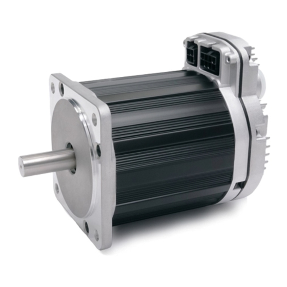
Parts of a ClearPath-SC Motor
ClearPath-SC Motor Components
Identifies and describes key components of a ClearPath-SC motor.
System Setup
Before Powering Up Your ClearPath-SC System
Essential pre-powering checks and safety guidelines for the system.
1. Install ClearView Software
Step-by-step guide for installing the ClearView software.
3. Connect ClearPath-SC System Components
24 Volt Logic Power Supply
Requirements and selection criteria for the 24VDC logic power supply.
System Hookup Diagram (With a Power Hub)
ClearPath-SC Hookup Diagram (for systems with a Power Hub)
Visual representation of system connections using a Power Hub.
System Hookup Diagram (Without Power Hub)
ClearPath-SC Hookup Diagram (for systems without a Power Hub)
Visual representation of system connections without a Power Hub.
5. Establish Communication (USB or RS-232 / Serial)
USB Communication
Steps for establishing communication via USB.
Setting the USB COM Port Manually
Procedure to manually configure the USB COM port in ClearView.
RS-232, Serial Communication
Instructions for establishing communication via RS-232 serial ports.
Test Spin Your Motors Using ClearView
ClearView Main UI
Overview of the ClearView software's main user interface elements.
Safety Warnings
Personal Safety Warnings
Guidelines for user safety when operating motion control equipment.
CE Compliance Warnings
Information regarding CE compliance and system responsibilities.
General Disclaimer
User responsibilities and limitations of product information.
Introduction
What is ClearPath-SC?
Defines ClearPath-SC as a multi-axis servo-controlled motion system.
Parts of a ClearPath-SC Motor
DC Bus Power Connector
Details the DC bus power input connector on the motor.
ClearPath I/O Connector
Describes the ClearPath I/O connector for communication and signals.
Diagnostic Port
Explains the diagnostic port for USB connectivity.
Status LED
Information on the status LED indicating motor operational status.
Auxiliary Protective Earth Connection Point
Describes the connection point for protective earth ground.
Example ClearPath-SC Systems
Typical 4-Axis System (Single Port, 1 SC4-HUB)
Example configuration of a 4-axis system with one SC4-HUB.
Powering a ClearPath-SC
Selecting a DC Bus Power Supply
Guidance on choosing the appropriate DC bus power supply.
FAQ: "What Size Power Supply Should I Use?"
Answers common questions about sizing DC bus power supplies.
Additional Power Supply Considerations
Operate in the 24-75VDC Range
Specifies the recommended operating voltage range for ClearPath-SC.
Why Avoid (Most) Switching Power Supplies
Explains the drawbacks of using switching power supplies for servo applications.
Teknic IPC-3 and IPC-5 Power Supplies
Teknic Model IPC-3
Details the Teknic IPC-3 power supply's capabilities.
Teknic Model IPC-5
Details the Teknic IPC-5 power supply's capabilities.
Power Supply Switching and Fusing
Power Supply On/Off Switch
Guidance on installing power switches on the AC input side.
DC Output Fuse
Recommendations for external DC output fusing.
Safety Disconnect Contactor
Information on using a power disconnect contactor for safety.
Using the Power4-Hub
Power4-Hub Overview Diagram
Diagram illustrating the Power4-Hub's connections in a system.
Parts of a Power4-Hub
Power4-Hub Component Descriptions
Details the various parts and connectors of the Power4-Hub.
Connections: One Power4-Hub
Single Power4-HUB System
Diagram showing connections for a single Power4-Hub system.
Connections: Two Power4-Hubs
Two Power4-HUBs Powering 8 ClearPath-SC Motors
Diagram illustrating system connections with two Power4-Hubs.
Power4-Hub LEDs
Power4-Hub LED Indicators
Explanation of the LEDs on the Power4-Hub board.
Communication and I/O (The SC4-Hub)
Introduction
Introduces the SC4-HUB as the central communication component.
SC4-HUB Overview
Details the SC4-HUB's interfaces and connectivity.
Parts of an SC4-Hub
SC4-HUB with Callouts
Diagram labeling the components and connectors of the SC4-HUB.
SC4-HUB Mounting
Information regarding the mechanical mounting of the SC4-HUB.
24VDC Input / Passthrough Connectors
Describes the 24VDC logic power input connectors.
USB Communication Connector (USB Comms)
Details the USB communication connector for PC connectivity.
ClearPath I/O Connector
Explains the ClearPath I/O connector for motor communication.
End-of-Loop Headers
Instructions for installing the end-of-loop jumper.
Input A and B Connectors
ClearPath-SC Input A and B Connector Diagram
Illustrates the wiring of Input A and B connectors.
Maximum Input Cable Length
Specifies the maximum recommended length for input cables.
Minimum Current Requirement
Defines the minimum current required for input devices.
Brake Control Connectors
Brake Control Connector Diagram
Diagram showing the brake control connectors on the SC Hub.
Brake Basics
Fundamental information about the brake control outputs.
Brake Control Circuit
Schematic: Brake Control 0
Circuit schematic fragment for Brake Control 0.
Caution: Brake Control Safety Note
Important safety considerations for brake control implementation.
Global Stop Connector
Schematic Snippet: Global Stop Input
Circuit schematic for the global stop input.
Configuration Software (ClearView)
Minimum System Requirements
Specifies the minimum hardware and software requirements for ClearView.
Installing ClearView Software
Provides instructions for installing the ClearView software.
Windows Update and ClearView Installation
Notes on Windows Update requirements for ClearView installation.
ClearView Software Tour
User Interface Overview
Describes the four main parts of the ClearView user interface.
Manual Motor Controls
ClearView Manual Controls Section
Overview of the Manual Controls section within ClearView UI.
Dashboard
ClearView Dashboard Section
Describes the Dashboard section of the ClearView UI.
Soft Scope
Soft Scope Overview
Introduces the ClearView Soft Scope for real-time data plotting.
Soft Scope Features
Lists the capabilities and features of the Soft Scope tool.
Scope Display and Scope Controls
ClearView Soft Scope Diagram
Diagram of the ClearView Soft Scope interface.
Strip Chart
ClearView Strip Chart Display
Shows the Strip Chart display for motor status and performance.
Strip Chart Legend
Key explaining the colors and symbols used in the Strip Chart.
ClearView Menus
File Menu
Describes the File menu options in ClearView.
Setup Menu
Input Actions
Configures actions to execute upon state changes at Input A or B.
Auto-Tune
Fine Tuning
Adjusts tuning performance for quietness or dynamic stiffness.
Operating Mode
Software Command
Sets motor control via application software and sFoundation library.
Step and Direction Pulse Input
Configures motor control using an external step and direction pulse source.
Quadrature A/B Pulse Input
Configures motor control using an external quadrature A/B pulse source.
Units
Units Setup
Selects units for displaying velocity and acceleration in ClearView.
Action Menu
Homing Actions
Controls and parameters for simulating and testing homing routines.
Clear E-Stop (Shift+F12)
Clears E-stop state and returns motors to previous operating states.
Clear All Exceptions (Shift+Ctrl+F12)
Clears exception states and messages from the system.
Enable All
Energizes all motors on the selected port.
Disable All
Disables all motors on the selected port.
Brake 0 and Brake 1 Control
Manually or automatically controls 24V inline brakes.
Details Menu
Tracking Error Limit
Sets the limit for tracking error to prevent shutdowns.
Move Status Indicators
Configures indicators for move completion and target status.
Input Filtering
Sets filtering parameters for input signals.
Deceleration Rate for E-stops
Sets the deceleration rate for E-stop events.
Vector Regen Shunt (VRS)
Enables Vector Regen Shunt for managing regenerated energy.
Actions Upon Disable
Defines actions to perform when a motor is disabled.
Power and Temperature Settings
Monitors and configures power and temperature parameters.
Move Status Indicators Setup
Setup dialog for move status indicators.
E-Stop Deceleration Rate Setup
Setup dialog for E-stop deceleration rate.
Vector Regen Shunt (VRS) Setup
Setup dialog for the Vector Regen Shunt feature.
Actions Upon Disable Setup
Setup dialog for actions upon motor disable.
Power and Temperature Status
Displays current power and temperature status.
Using the Diagnostic Channel
Terms Used in this Section
Defines key terms used when discussing the diagnostic channel.
Connecting to the Diagnostic Channel
ClearView's Motor List
Shows how motors appear in ClearView's motor list.
Application Settings Window
Illustrates the Application Settings window in ClearView.
Select the Diagnostic COM Port
Steps to select the diagnostic COM port in ClearView preferences.
Application Channel vs. Diagnostic Channel
Compares the roles of the application and diagnostic communication channels.
Changing Diagnostic Channel Access Modes
Monitor Mode
Diagnostic channel access mode allowing scope viewing only.
Tune Mode
Access mode for scope viewing and tuning parameters.
Full Access Mode
Diagnostic channel has full control over the motor settings.
Troubleshooting Diagnostic Channel Connections
Manually Selecting COM Ports
Procedure for manually selecting COM ports in ClearView.
Software Library and SDK Overview
Introduction to the sFoundation Library
Overview of the sFoundation motion control class library.
What's Covered in this Section
Lists topics covered in the software library section.
sFoundation Class Hierarchy
Explains the logical hierarchy of sFoundation classes.
INode (Node Level Classes)
Features/Actions
Lists key features and actions available for INode objects.
Other Node Level Classes
Introduces other node-level classes like IMotion and IInfo.
IPort (Port Level Classes)
IStatus
Accesses and manages node status information.
IStatusAdv
Manages advanced node status and position capture registers.
IHoming
Provides hooks into Teknic's homing engine.
ILimits
Accesses global torque and positional tracking error limits.
ISetup
Manages node setup features like loading configuration files.
Port Features/Actions
Lists key features and actions for port-level classes.
SysManager (System Level Class)
Other Port Level Classes
Describes additional port-level classes like IGrpShutdown and IBrakeControl.
Common Features
Lists common features of the SysManager class.
Software Development Kit (SDK)
Where Is the SDK Located?
Provides paths to find the ClearView SDK files on your computer.
Appendix B: Mechanical Index
Mounting Dimensions: ClearPath-SC NEMA 34
Provides mounting dimensions for ClearPath-SC NEMA 34 motors.
Mounting Dimensions: ClearPath-SC NEMA 23
Provides mounting dimensions for ClearPath-SC NEMA 23 motors.
Connecting ClearPath-SC to a Mechanical System
Motor Connection: General Tips and Guidelines
Provides general tips for connecting motors to mechanical systems.
Motor Connection Best Practices
Covers best practices like clamping, belts, keys, and direct loads.
Notes on Coupling Selection.
General Guidelines for Coupling Selection
Offers guiding principles for selecting servo application couplings.
Coupling Recommendation
Recommends zero-backlash curved jaw couplings for servo applications.
Installing Pulleys and Pinions
Bellows Couplings and Web Information
Discusses bellows couplings and coupling information resources.
Pulley and Pinion Mounting
Provides guidelines for mounting pulleys and pinions.
About End-of-Travel Stops.
Hard Blocks
Describes the use of hard blocks as end-of-travel stops.
Elastomeric (Rubber) Stops
Explains the use of elastomeric stops for shock absorption.
Pneumatic (Dashpots)
Details pneumatic dashpots for shock absorption.
End Stops and Hard Stop Homing
Discusses end stops for hard stop homing applications.
Appendix D: Specifications
ClearPath-SC Motor: Common Specifications
Lists common electrical, bearing, and environmental specifications for motors.
Environmental Sealing, Compliance, and Warranty
Details environmental sealing ratings, certifications, origin, and warranty.
Appendix E: Grounding and Shielding
Protective Earth (PE) Connection
Methods for connecting the system to Protective Earth (PE).
Grounding and Shielding
Guidelines for maintaining separation of control and power grounds.
Power Returns
Instructions for proper power return wiring.
Appendix F: Circuit Schematics
Power4-Hub Schematic (Simplified)
Simplified circuit schematic for the Power4-Hub.
SC4-Hub Schematic (Simplified) - Page 1
Simplified circuit schematic for the SC4-Hub (Part 1).
SC4-Hub Schematic (Simplified) - Page 2
Simplified circuit schematic for the SC4-Hub (Part 2).
Appendix G: Wiring the Inputs
Wiring a Mechanical Switch to an Input
Example wiring for a mechanical switch connected to an SC Hub input.
Wiring a 24V NPN Sensor to an Input
Example wiring for a 24V NPN sensor connected to an SC Hub input.
Appendix K: ClearPath-SC Cable Pinouts
CPM-CABLE-CTRL-MU120
Pinout information for the CPM-CABLE-CTRL-MU120 cable.
CPM-CABLE-CTRL-MM660
Pinout information for the CPM-CABLE-CTRL-MM660 cable.
CPM-CABLE-PWR-MM660
Pinout information for the CPM-CABLE-PWR-MM660 cable.
CPM-CABLE-PWR-MS120
Pinout information for the CPM-CABLE-PWR-MS120 cable.
Need help?
Do you have a question about the POWER4-HUB and is the answer not in the manual?
Questions and answers