
Related Manuals for Teknic CLEARPATH-EC


Summary of Contents for Teknic CLEARPATH-EC
- Page 1 ANUAL LEAR CAT C THER OMPLIANT ANUAL IP67/66K NEMA 23 NEMA 34 F RAME IZES 1.11 / J 17, 2024 ERSION...
- Page 2 - E C U 1 . 1 1 L E A R A T H S E R A N U A L R E V HIS PAGE INTENTIONALLY LEFT BLANK . (585) 784-7454 EKNIC...
-
Page 3: Table Of Contents
Setting Up ClearView 3.0 Software ..........17 ClearView 3.0 Minimum System Requirements..... 17 Download and Install ClearView 3.0....... 17 Connecting a ClearPath-EC Motor to Your PC ....18 Open ClearView 3.0 (Motor Setup Program)....19 Test Spin Your Motors Using Motion Generator ......20 If You See Exceptions, Warnings, or Motor Shutdowns..... - Page 4 POWER4-STRIP-S............... 41 POWER4-STRIP-S: Things to Know....... 41 Other Power Supply Topics ............43 The "Ideal" DC Bus Power Supply........43 Teknic IPC-3 and IPC-5 ...........43 Underpowered DC Bus Motor Power Supplies ....44 Switching Power Supplies..........44 Power Supply Compliance Notes........44 Power Supply Switching and Fusing .......45 FAQ: "What size DC Bus Motor Power Supply should I...
- Page 5 ..77 PPENDIX ONNECTOR AND ABLE EFERENCE Mating Connectors............... 77 Power4-Hub-S, Power4-Strip-S, IPC-5......77 M12 Adapter (P/N: M12-ENET-CON) ......78 Cable Drawings (Links To Teknic.com) ........79 D: S ........80 PPENDIX PECIFICATIONS ClearPath-EC Motor: Common Specifications......80 POWER4-HUB-S .................83 POWER4-STRIP-S...............84 E: G ....
-
Page 6: Safety Warnings
- E C U 1 . 1 1 L E A R A T H S E R A N U A L R E V AFETY ARNINGS IMPORTANT: Please read this safety information before attempting to install, apply power to, or operate a ClearPath motor. Failure to understand and follow the safety information presented in this document could result in property damage, bodily injury or death. -
Page 7: General Disclaimer
If Teknic’s products are used in an application that is safety critical, the User must provide appropriate safety testing of the products, adequate safety devices, guarding, warning notices and machine-specific training to protect the operator from injury. -
Page 8: Introduction
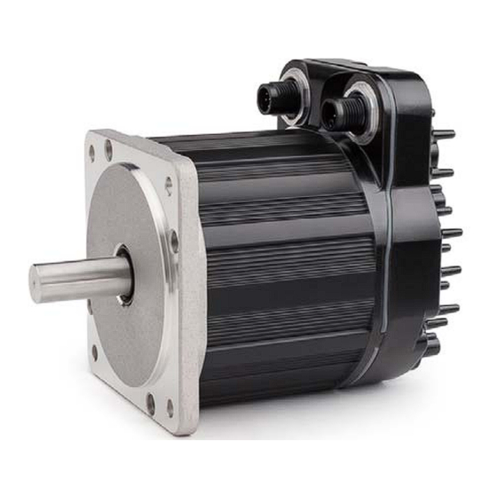
HAT IS A LEAR OTOR ClearPath-EC is an all-in-one servo system consisting of a precision brushless servo motor (with encoder) combined with a powerful integrated servo drive, internal servo controller and EtherCAT interface, all contained in a housing that's about the size of a typical standalone servo motor. - Page 9 Absolute Position Feedback functionality is standard. Logic Power for a group of ClearPath-EC motors can be supplied by a battery and charger, preserving position information even during a power loss, lockout, or machine safety event. For most machines, it’s easy to keep the absolute position function active for days using a widely available, inexpensive 12V battery and charger.
-
Page 10: Parts Of A Clearpath-Ec Motor
USB-IR Converter to connect ClearPath to a Windows PC running ClearView 3.0. USB-IR Converter - (Teknic part# CPMS-USB-IR) This device translates USB signals to and from high speed infrared light pulses facilitating communication between a ClearPath motor and a PC running ClearView 3.0 software. -
Page 11: Top Tips For Clear Path -Ec Users
Auto-Tune Your Motor Fully Loaded. Always run Auto-Tune with your ClearPath-EC motor coupled to the mechanical system, exactly as it will run during normal machine operation. Note: The default motor tuning file that comes with your motor is designed for no-load operation. -
Page 12: Quick Start Guide
S E R A N U A L R E V UICK TART UIDE This section was designed to help you get your ClearPath-EC motor up and running quickly and safely. ECTION Downloading and installing ClearView 3.0 (setup and configuration software) -
Page 13: Clearpath Quick Setup
Power distribution board (POWER4-HUB-S or POWER4- STRIP-S) Logic Power Backup Supply (12-75VDC). Required only if using Power4-HUB-S. USB-IR Converter (Teknic PN CPMS-USB-IR) USB A-C data cable, Teknic PN: CPM-CABLE-USB-118AC ECOMMENDED TEMS M12 Adapter, P/N M12-ENET-CON Network & I/O cables ECURE... -
Page 14: Power Up Your Clearpath-Ec Motor
LEAR OTOR HINGS YOU LL NEED DC Bus Motor Power Supply: Teknic/IPC-5, 75VDC Bus Motor Power Supply or equivalent, cables as shown below. Power distribution board: POWER4-HUB-S or POWER4- STRIP-S. Note: for POWER4-HUB-S users, a separate Logic Supply is required (12-75VDC). A separate Logic Supply is not required when using a POWER4-STRIP-S. - Page 15 IMPORTANT: Reversing DC Bus Power polarity will permanently damage your ClearPath motor. Important Notes If using Teknic manufactured cables, you can safely skip this test. Do not force or jam DMM probes into the connector. Use smaller probe tips or find a safe alternative way to verify that polarity is correct.
-
Page 16: Power-Up Procedure
- E C U 1 . 1 1 L E A R A T H S E R A N U A L R E V OWER ROCEDURE IMPORTANT: Start with power supplies turned off. See note below. 2. Connect cables as shown earlier in this section. 3. -
Page 17: Setting Up Clearview 3.0 Software
1280 x 1024 pixels or higher OWNLOAD AND NSTALL LEAR Download the ClearView 3.0 installer from: https://www.teknic.com/downloads/. 2. Launch the ClearView 3.0 installer. Follow the on-screen prompts to complete installation. Note: ClearPath-EC motors are compatible with ClearView 3.0 or later. . (585) 784-7454 EKNIC... -
Page 18: Connecting A Clearpath-Ec Motor To Your Pc
ClearPath does not require a USB to PC connection during normal machine operation. The diagnostic communication scheme allows all ClearPath-EC motors to be sealed to IP67/66K without having to depend on sealing from auxiliary covers when not in use. NOTE: The CPMS-USB-IR adapter is not sealed and should not be left installed in wet environments. -
Page 19: Open Clearview 3.0 (Motor Setup Program)
LEAR OTOR ETUP ROGRAM After you open ClearView 3.0, your ClearPath-EC motor will attempt to establish communication with your PC. When successfully connected, the ClearView 3.0 UI will look similar to that of the figure shown below. UI F EATURES... -
Page 20: Test Spin Your Motors Using Motion Generator
ENERATOR Note: This section describes how to spin an unloaded motor (i.e. a motor with nothing attached to the shaft). Important: ClearPath-EC motors ship out pre-configured for unloaded use only. You must run the Auto- Tune application whenever you connect your motor to a different mechanical system. -
Page 21: If You See Exceptions, Warnings, Or Motor Shutdowns
IF THE MOTOR'S STATUS LED FLASHES RED, your ClearPath motor has identified an internal hardware problem and may need to be returned for repair or replacement. Please contact Teknic if this happens. UNING Tuning is required whenever you bolt a ClearPath motor to a new or different mechanical system. -
Page 22: Before You Seek Technical Help
- E C U 1 . 1 1 L E A R A T H S E R A N U A L R E V TARTING THE UNER In ClearView 3.0, click Setup>Tuning>Auto-Tune. Start the Auto-Tuner Important: The Auto-Tune application was designed to walk the user through the tuning process in a safe, step-by-step manner. - Page 23 If you see a shutdown accompanied by a red flashing LED, you’ll probably have to return your ClearPath for repair or replacement. Check the Teknic website for repair/return information. How do I restore my ClearPath to its factory default settings? If you need to return ClearPath to its original state (i.e., configured exactly...
-
Page 24: Connecting To An Ether Cat Network
CAT N ONNECTING TO AN THER ETWORK This section discusses how ClearPath-EC motors can be integrated into your EtherCAT machine topology. The ClearPath-EC system: Features the same compact motor size as other ClearPath models Works with standard, off-the-shelf network patch cables (CAT 5... -
Page 25: M12 Adapter (Teknic P/N: M12-Enet-Con)
M12 A P/N: M12-ENET-CON) DAPTER EKNIC Each ClearPath-EC motor must be paired with an M12 Adapter. M12 Adapters can be mounted wherever it makes sense to route EtherCAT network cables and ClearPath-EC motors. M12 Adapter features Provides access to EtherCAT network signals via standard network patch cables (CAT-5 and above). - Page 26 I/O-A2 I/O-A1 I/O-B1 Jumper Brake P M12 Adapter (Teknic P/N: M12-ENET-CON) Engineers Note: M12 Adapter Schematics This document includes a schematic of the M12 Adapter in Appendix G general reference, and for customers who would like to port the functionality of the M12 Adapter into their own custom device. As an example, a machine builder might consider designing a multi-axis version of the M12 Adapter, or adding their own customized I/O functionality.
-
Page 27: Inputs And Outputs
-EC I/O C VERVIEW LEAR IRCUITS ClearPath-EC motors include two fully-protected, fully-isolated, high- speed digital I/O circuits for connecting sensors, actuators, and logic level devices. These circuits are referred to as I/O-A and I/O-B in this document. The I/O signals are routed from the M12 Adapter to the motor by means of a controller cable. - Page 28 - E C U 1 . 1 1 L E A R A T H S E R A N U A L R E V or source current as outputs, and independently be driven from sinking or sourcing devices when used as inputs. You may also note that each I/O circuit is protected by a 48V bi- directional clamp diode to protect against inductive kickback from connected coils (relays, contactors, solenoid valves, etc.)
-
Page 29: Clearpath-Ec Inputs
Maximum input current for given input voltages DAMAGE WARNING: C LEAR NPUTS ClearPath-EC inputs are robust, but there are some situations where they can be damaged. For example, connecting 75VDC bus power across an input will kill it. . (585) 784-7454... -
Page 30: Input Wiring Examples
XAMPLES Input A, and Input B, are designed for use with 5-24VDC logic levels and pulses from a wide variety of signal sources and devices including PLCs, microcontrollers, and mechanical switches. ClearPath-EC Inputs (ClearPath internal) Sourcing (PNP) Sensor A1 (B1) - Page 31 While differential drivers may work initially, they may fail over time as the environment changes, i.e. the motor heats up, components age, and so forth. This can result in erratic operation that is difficult to debug. ClearPath-EC Input (ClearPath Internal) A1 (B1)
-
Page 32: Clearpath-Ec Outputs
- E C U 1 . 1 1 L E A R A T H S E R A N U A L R E V -EC O LEAR UTPUTS When I/O-A or I/O-B are configured as outputs, they support a wide range of devices including relay coils, logic inputs, LEDs, etc. -
Page 33: Output Wiring Examples
- E C U 1 . 1 1 L E A R A T H S E R A N U A L R E V UTPUT IRING XAMPLES Any external circuit or device to be connected to the ClearPath output should conform to the guidelines below. - Page 34 - E C U 1 . 1 1 L E A R A T H S E R A N U A L R E V OURCING UTPUT A or B can be used as a sourcing switch as shown below. 5-24VDC (Supply) ClearPath Internal...
- Page 35 - E C U 1 . 1 1 L E A R A T H S E R A N U A L R E V UTPUT PPLICATION XAMPLES Driving an LED The output circuits are not internally powered; they require an external 5– 24VDC power supply capable of supplying at least 10mA.
-
Page 36: Wiring An Axis Brake (Output B Only)
- E C U 1 . 1 1 L E A R A T H S E R A N U A L R E V IRING RAKE UTPUT ONLY The Network Adapter includes a built-in protected circuit designed to drive an axis brake directly. -
Page 37: Powering Clear Path -Ec
OWERING LEAR NTRODUCTION ClearPath-EC motors in this family require a DC Bus Motor Power Supply such as the Teknic IPC-5 (75VDC) described later in this section and online here. Note: Properly specified third-party power supplies may also work with ClearPath-EC motors. -
Page 38: Power Distribution Boards
ClearPath motors in this family require a power distribution interconnect system to supply DC Bus Motor Power and Logic Power to the motor's power connector. Teknic offers two power distribution boards depending on your needs: The POWER4-HUB-S and the POWER4-STRIP-S. -
Page 39: Power4-Hub-S System Diagram
- E C U 1 . 1 1 L E A R A T H S E R A N U A L R E V POWER4-HUB-S S YSTEM IAGRAM POWER4-HUB-S Logic Power Power Distribution Board DC Bus Power Supply Backup Supply With Logic Power Backup (IPC-5 shown) -
Page 40: Power4-Hub-S: Things To Know
- E C U 1 . 1 1 L E A R A T H S E R A N U A L R E V POWER4-HUB-S: T HINGS TO IMPORTANT: Never connect two IPC-3 / IPC-5 power supplies to a single POWER4-HUB-S. These power supplies are not designed to operate in parallel or series configurations. -
Page 41: Power4-Strip-S
- E C U 1 . 1 1 L E A R A T H S E R A N U A L R E V POWER4-STRIP-S The POWER4-STRIP-S Distributes DC Bus Motor Power to up to four ClearPath motors. This board serves as a basic plug strip for your ClearPath motors. - Page 42 - E C U 1 . 1 1 L E A R A T H S E R A N U A L R E V power supply will cause electrical arcing that will damage the connectors over time. Do not connect more than two POWER4-STRIP-S boards to a power supply.
-
Page 43: Other Power Supply Topics
…can deliver high peak current (for short periods) and effectively manage regenerated energy (reverse voltage that returns to the power supply and can overload it). Teknic’s IPC-3 and IPC-5 are designed with these requirements in mind. “Bulk” linear power supplies—basically a transformer, rectifier, and large capacitor—can also work well with servo systems... -
Page 44: Underpowered Dc Bus Motor Power Supplies
UPPLY OMPLIANCE OTES Any 3rd party (non-Teknic) power supply used with the POWER4-HUB-S or PWR-STRIP-S, should be current limited or fused to 25A or less using a 25A, >100VDC fuse. If UL compliance is a consideration, select a UL Listed DC fuse. -
Page 45: Power Supply Switching And Fusing
If you need to power several motors running at high speed and high torque, consider using a Teknic IPC-5, 75VDC power supply. Start with one supply but keep in mind that you can add another supply later if your application requires more power. -
Page 46: Software (Clear View 3.0)
Sound card with speakers (optional) 3.0 S NSTALLING LEAR OFTWARE Download the ClearView 3.0 installer from https://www.teknic.com/downloads/. Launch the ClearView 3.0 installer. 3.0 S LEAR OFTWARE The ClearView 3.0 UI consists of four main parts: the Menu, Manual Controls, Dashboard, and Soft Scope. -
Page 47: Manual Motor Controls
OTOR ONTROLS The Manual Motor Controls are a set of tools designed to help you test and exercise your ClearPath-EC motors without a Master and without writing code. Manual Controls allow you to: Enable, disable, and E-stop motors Manually jog motors... -
Page 48: Dashboard
- E C U 1 . 1 1 L E A R A T H S E R A N U A L R E V ASHBOARD The Dashboard contains a number of visual elements (virtual LEDs, meters, numerical readouts) to give the user real-time access to key motor information including motor status, encoder position, motor velocity, bus voltage, I/O states, exception messages, etc. -
Page 49: Soft Scope
A N U A L R E V COPE VERVIEW The Soft Scope takes real-time streaming data from your ClearPath-EC motor and plots it on a scope display similar to that of a hardware oscilloscope. The Soft Scope can display the motor’s actual torque output, following error, commanded velocity, acceleration, and more. - Page 50 - E C U 1 . 1 1 L E A R A T H S E R A N U A L R E V COPE ISPLAY AND ONTROLS The ClearView Scope display is modeled after a typical hardware oscilloscope.
- Page 51 - E C U 1 . 1 1 L E A R A T H S E R A N U A L R E V averaging effect on the displayed waveform that can help mitigate the effect of noise (or just remove visual clutter) on the displayed signal. Scope Filter = OFF Scope Filter = MEDIUM Effect of Scope Filter on trace display...
- Page 52 - E C U 1 . 1 1 L E A R A T H S E R A N U A L R E V (continued) Trigger Source "Trigger On" menu lets you choose what conditions must be met before scope data collection is triggered. (For use with Normal and Single modes only.) If Trigger Source is set to: Soft Scope will:...
- Page 53 - E C U 1 . 1 1 L E A R A T H S E R A N U A L R E V Cursor Readings Displays time and amplitude measurements of the vertical and horizontal cursors on your scope display. Click the Measure Move button to automatically place the vertical cursors at the beginning and end of a move to quickly determine total move time.
-
Page 54: Clearview 3.0 Menus
Save Configuration. Used to save your ClearPath-EC motor configuration file as a .mtr file. Reset Config File to Factory Defaults. Restores ClearPath-EC to its factory default configuration (i.e., the way it was configured when you received it). All existing settings will be overwritten. Save your current configuration as a .mtr file (described above) if you think you'll need to... -
Page 55: Edit Menu
Cut, Copy, Paste. (Standard Windows commands) Motor ID. Opens a window where you can enter a name and brief description for your ClearPath-EC motor. Zero Position. Sets the Position Counter to zero. Note: In certain modes, double-clicking the Position Counter directly in the UI will also zero the position counter. -
Page 56: Setup Menu
- E C U 1 . 1 1 L E A R A T H S E R A N U A L R E V ETUP Setup Window Tuning Auto-Tune. Opens the Auto-Tune wizard which walks the user through the Auto-Tune process in a safe, step-by-step manner. It is important to read all instructions and safety warnings when using the Auto-Tune wizard. - Page 57 - E C U 1 . 1 1 L E A R A T H S E R A N U A L R E V Torque Limiting. Opens a window that lets the user set a Global Torque Limit (this sets the same torque limit in either direction) or Directional Torque Limits (this sets separate torque limits in each direction).
-
Page 58: Action Menu
Velocity Acceleration CTION Action Menu E-Stop All. Issues an E-stop (node stop) to all ClearPath-EC motors on the port. Clear E-Stop. Clears E-stop and returns motor to previous operating states. Clear All Exceptions. Clears exception state and messages. Note: The exception condition may recur if the underlying cause of the exception still exists. - Page 59 - E C U 1 . 1 1 L E A R A T H S E R A N U A L R E V Output B (Brake). Lets the user manually control a brake (if Output B is configured for brake control).
-
Page 60: Additional Features Menu
- E C U 1 . 1 1 L E A R A T H S E R A N U A L R E V DDITIONAL EATURES Additional Features Menu Following Error Limit. Following error is defined as the difference between the encoder's commanded position and its actual position. - Page 61 - E C U 1 . 1 1 L E A R A T H S E R A N U A L R E V Input A, B Filtering. See dialog text for details. Vector Regen Shunt. See dialog text for details. .
- Page 62 A T H S E R A N U A L R E V Disable and Stop Options. Opens a multi-tab window with options regarding how the ClearPath-EC motor will behave upon Disable, Quick Stop, and Halt Commands. Disable Options Halt Options Quick Stop Options .
-
Page 63: Ethercat Parameters Menu
- E C U 1 . 1 1 L E A R A T H S E R A N U A L R E V Power and Temperature Settings and Status. Use these settings to: Configure ClearPath to shut down or issue a warning when DC bus voltage falls below the Low Voltage Exception Threshold. -
Page 64: Access Menu
Access is required to perform certain tasks in ClearView 3.0, such as using the Soft Scope, Auto-Tuning, and changing parameters and settings. See the following section (Using the Diagnostic Port) for full details on how to connect a diagnostic computer to a ClearPath-EC motor. . (585) 784-7454 EKNIC... -
Page 65: Using The Diagnostic Port
ClearPath-EC motors. Diagnostic Port. This is a secondary data channel that sends data between the ClearPath-EC and a separate PC running ClearView 3.0. The Diagnostic Port is accessed via the USB-IR Port on the back of the motor. - Page 66 - E C U 1 . 1 1 L E A R A T H S E R A N U A L R E V HANGING IAGNOSTIC CCESS ODES Set the access level from the Access menu in ClearView 3.0. Users primarily use Monitor Mode or Tune Mode.
-
Page 67: Clear Path -Ec Software Reference
L E A R A T H S E R A N U A L R E V -EC S LEAR OFTWARE EFERENCE The ClearPath-EC Software Reference Manual is available on the Teknic Downloads page. See link below: https://teknic.com/files/downloads/ClearPath-EC_Software_Reference.pdf . (585) 784-7454 EKNIC... -
Page 68: Appendix A: Troubleshooting
- E C U 1 . 1 1 L E A R A T H S E R A N U A L R E V A: T PPENDIX ROUBLESHOOTING LED B LINK ODES Status LED Sealing Tri-color LED USB-IR Port Gasket Green LED* Port 1 Link Activity... -
Page 69: Appendix B: Mechanical Reference
S E R A N U A L R E V B: M PPENDIX ECHANICAL EFERENCE IMENSIONED RAWINGS INKS OTORS NEMA 23 Frame ClearPath-EC Motor (IP66K/67) NEMA 34 Frame ClearPath-EC Motor (IP66K/67) OWER ISTRIBUTION OARDS POWER4-HUB-S POWER4-STRIP-S CCESSORIES CPMS-USB-IR CPM-COVER-USB-5P . -
Page 70: Motor Mounting Considerations
OTOR OUNTING ONSIDERATIONS Tip: Teknic recommends mounting the motor such that the IR communication port and status LED are visible and accessible when the motor is mounted to the machine. Do not mount ClearPath over a heat source such as a deep fryer, heater, or hot exhaust pipe. -
Page 71: Motor Connection: General Tips And Guidelines
This section contains information and tips on how to safely and securely couple a servo motor to a mechanical system. For more information on this topic, visit the Teknic website: https://teknic.com/securing-mechanics-motor-shafts/ Align with care. When connecting two shafts—such as a motor shaft to a screw shaft—the rotating centers must be... - Page 72 A N U A L R E V Avoid using shaft keys when possible. Although ClearPath includes a keyway feature on the shaft, Teknic does not generally recommend the use of keys. Keys tend to cause run- out and backlash errors, particularly in reciprocating, precision positioning motion applications.
-
Page 73: Notes On Coupling Selection
For more information on this topic, visit the Teknic website: https://teknic.com/securing-mechanics-motor-shafts/ General Guidelines for Coupling Selection Teknic has a few guiding principles when it comes to coupling selection for servo applications. Keep in mind that these are rules of thumb and may not apply to every application. In general: Don’t undersize the coupling. -
Page 74: Installing Pulleys And Pinions
- E C U 1 . 1 1 L E A R A T H S E R A N U A L R E V misalignment or axial motion. Also, never exceed the manufacturer’s rating for “maximum torque with zero backlash” when using jaw couplings. -
Page 75: About End-Of-Travel Stops
- E C U 1 . 1 1 L E A R A T H S E R A N U A L R E V BOUT RAVEL TOPS End-of-travel stops are typically installed to prevent the moving element of a linear axis from flying off the machine in the event of a use or control error. -
Page 76: Fan Mounting
- E C U 1 . 1 1 L E A R A T H S E R A N U A L R E V OUNTING PTIONAL ClearPath motors include unthreaded mounting bosses on the rear casting to accommodate a standard computer fan (60mm for NEMA 34 motors, or 40mm for NEMA23 motors). -
Page 77: Appendix C: Connector And Cable Reference
39-00-0046 (reel) Female crimp terminal, 63819-1000 22 AWG 4 circuits 39-03-9042 (black, UL 94V-0) 39-00-0047 (loose) tin plate, 22-28 AWG (22-28 AWG) (Pins 1,4) AWG values listed are the actual wire gauges used in Teknic-manufactured cables. . (585) 784-7454 EKNIC... -
Page 78: M12 Adapter (P/N: M12-Enet-Con)
- E C U 1 . 1 1 L E A R A T H S E R A N U A L R E V M12 A (P/N: M12-ENET-CON) DAPTER M12, A-code 12-Pin Molex Min-Fit Jr. 8-Position Header I/O-B2 24V Ret. -
Page 79: Cable Drawings (Links To Teknic.com)
- E C U 1 . 1 1 L E A R A T H S E R A N U A L R E V ABLE RAWINGS INKS EKNIC CPMS-CABLE-NET-AA039 CPMS-CABLE-NET-AA120 CPMS-CABLE-NET-AA315 CPM-CABLE-CTRL-MU120 CPMS-CABLE-PWR-KM120 CPMS-CABLE-PWR-KK660 PC-SBR-72 On tightening M12 connectors. For a reliable seal, tighten the communication and power cables between 0.8 Nm-1.4 Nm. -
Page 80: Appendix D: Specifications
Microsoft Windows 10 or later IR to USB-C adapter securing method Magnetic Mating IR to USB-C converter (required) Teknic part number: CPMS-USB-IR Electrical Power Requirements, Motor Bus Supply: Bus Supply Voltage, Typical: 24VDC to 75VDC Bus Supply Voltage, Absolute Min: 21.5VDC (as measured at input terminals) - Page 81 - E C U 1 . 1 1 L E A R A T H S E R A N U A L R E V Continuous Bus Current, Typical: 1A to 4A (application dependent) Continuous Bus Current, Maximum: Disabled Power, Maximum 20mW Enabled Power @ 75V (zero shaft torque) <1W...
- Page 82 EN 61034-5 Materials used within RoHS, REACH, Conflict Minerals Country of Origin: Warranty: 3 years The RMS torque limit on certain motors is derated for operation in ambient temperatures above +40°C. Contact Teknic for derating assistance. . (585) 784-7454 EKNIC...
-
Page 83: Power4-Hub-S
- E C U 1 . 1 1 L E A R A T H S E R A N U A L R E V POWER4-HUB-S DC Bus Motor Power (Input from DC Bus Motor Supply) Nominal voltage range 24VDC to 75VDC Max. -
Page 84: Power4-Strip-S
- E C U 1 . 1 1 L E A R A T H S E R A N U A L R E V POWER4-STRIP-S DC Bus Motor Power (Input from DC Bus Motor Supply) Nominal voltage range 24VDC to 75VDC Max. -
Page 85: Appendix E: Grounding And Shielding
- E C U 1 . 1 1 L E A R A T H S E R A N U A L R E V E: G PPENDIX ROUNDING AND HIELDING (PE) C ROTECTIVE ARTH ONNECTION Compliance Note: ClearPath must be properly connected to the machine’s Protective Earth terminal to meet EMC emissions/immunity specification EN-61800-3, as well as electrical safety specification EN- 61010 (for CE/UL compliance). -
Page 86: Power Returns
- E C U 1 . 1 1 L E A R A T H S E R A N U A L R E V OWER ETURNS Never use the machine frame or chassis as a power return. Use discrete cable or wires for all power wiring. - Page 87 - E C U 1 . 1 1 L E A R A T H S E R A N U A L R E V F: C PPENDIX LEAR C P M - E C H P - 3 4 4 1 F - R L N B Example Part Number ®...
-
Page 88: Appendix G: M12 Adapter Schematic
- E C U 1 . 1 1 L E A R A T H S E R A N U A L R E V G: M12 A PPENDIX DAPTER CHEMATIC NetA_TX+ NetA_TX- NetA_RX+ NetA_RX- NetB_TX+ NetB_TX- NetB_RX+ NetB_RX- . -
Page 89: Appendix H: Miscellaneous Topics
Instructions Select a Logic Power Backup Supply. Typically 12V or 24V, but can be any voltage from 12V-75V. 2. Order a Teknic CPM-CABLE-M2P2P-120. This is a 120" (10-ft.), 2-pin Molex to 2-pin Molex cable as shown below. CPM-CABLE-M2P2P-120 20 AWG... - Page 90 1 . 1 1 L E A R A T H S E R A N U A L R E V Teknic, Incorporated 7650 Omnitech Pl Victor, NY 14564 © 2024 TEKNIC INCORPORATED, ALL RIGHTS RESERVED . (585) 784-7454 EKNIC...
Need help?
Do you have a question about the CLEARPATH-EC and is the answer not in the manual?
Questions and answers