
Related Manuals for Aclara SGM1412-B


Summary of Contents for Aclara SGM1412-B
- Page 1 SGM1400-B Series Smart Meter Single Phase User Manual - SMETS2 Y20974-TUM Revision B www.Aclara.com...
- Page 3 Disclaimer The information in this document is subject to change without notice and should not be construed as a commitment by Aclara. Aclara assumes no responsibility for any errors that may appear in this document. No responsibility is assumed for the use or reliability of software on equipment that is not supplied by Aclara.
- Page 4 S G M 1 4 0 0 S e r i e s S m a r t M e t e r U s e r M a n u a l – S M E T S 2...
- Page 5 OMPLIANCE WITH TANDARDS AND UROPEAN IRECTIVES Meters are marked with the European CE mark in accordance with the Marking Directive 93/68/EEC to indicate compliance with the requirements of the EMC directive and Measuring Instruments Directive 2004/24/EC. Safety requirements for meters are addressed in specific metering standards outlined below.
- Page 6 It does not relieve the user of responsibility to use sound practices in application, installation, operation, and maintenance of the equipment purchased. Aclara reserves the right to make changes in the specifications shown herein or to make improvements at any time without notice or obligations. Should...
-
Page 7: Table Of Contents
Chapter 1: Introduction Aclara Support ........1 Chapter 2: Product Description General Information . - Page 8 Table of Contents Firmware Variants ....... . .24 Firmware Components .......25 Firmware Specifications .
- Page 9 Table of Contents Asynchronous Billing ....... .43 Chapter 6: Advanced Features Supply Disconnect and Reconnect .
- Page 10 Table of Contents UTRN Entry Responses ......62 UTRN Entry Accepted ......62 UTRN Entry Lockout .
-
Page 11: Chapter 1: Introduction
All work must be done in accordance with local utility safety practices and procedures. Aclara Support If you have questions, an issue, or would like to speak with Aclara's Support personnel, please contact Aclara using one of the following methods. Technical Support Email support@aclara.com... - Page 12 Aclara Support S G M 1 4 0 0 S e r i e s S m a r t M e t e r U s e r M a n u a l – S M E T S 2...
-
Page 13: Chapter 2: Product Description
HAPTER RODUCT ESCRIPTION The SGM1400-B meter from Aclara is an advanced modular designed family of products for domestic and small commercial installations. The SGM1400-B is available in both single phase and dual element variants, and it forms an integral part of a complete two-way, secure, end-to-end solution. -
Page 14: General Information
General Information The meters also support a comprehensive tariff developed in association with the UK Great Britain Companion Specifications Standard and supports both Seasonal Time of Day (STOD) and block tariffs. Additionally, the meters offer storage for two years of load profile data and support independent profiling of instrumentation values, typically line voltage, current, frequency, etc. - Page 15 Chapter 2 • Product Description • Two years of load profile data storage • Three months instrumentation profile data • Daily, weekly, and monthly billing data • Voltage sag/swell, under and over voltage • Over and Under Frequency • Power Factor Threshold •...
-
Page 16: Features
General Information • Tariff Structure (secondary element): • 50 Special Days • 4 Week Profiles • 4 Time-of-Use Registers • 16 Day Profiles • 4 Seasons Features The SGM1400-B Series smart meter family has the following main features: • 640 kB of RAM temporary data storage, 164 MB of Serial Flash Memory for non-volatile data storage, and 1.5 MB of Internal (on-chip) program memory •... -
Page 17: Models
Chapter 2 • Product Description Models The SGM1400-B Series smart meter family is made up of meters of common physical characteristics and functionality. The nomenclature of the meter models indicates the following: The following models are currently available in the SGM1400-B smart meter family: 100 A 100 A... - Page 18 Terminal Arrangements SGM1415-B SGM1416-B SGM1422-B S G M 1 4 0 0 S e r i e s S m a r t M e t e r U s e r M a n u a l – S M E T S 2...
-
Page 19: Chapter 3: Physical Components
Chapter 3 • Physical Components CHAPTER HYSICAL OMPONENTS The SGM1400-B Series smart meter family comprises of a single phase and single phase with 2 A relay output. The main physical features of a SGM1400-B Series meter are shown below. Enclosure and Covers The SGM1400-B Series meters use a thermally stable, UV-protected polycarbonate enclosure that is double insulated to protective Class II. -
Page 20: Cover Seals
Cover Seals Cover Seals The meter cover and terminal cover are secured by standard single sealing screws. The torque value for the sealing screw is 0.6-0.9 Nm. The screw head has a recessed hole and slot to accommodate a 0.914 mm diameter thread wire seal. The sealing wire is crimped close to the body of the meter using a tool with die indents. -
Page 21: Descriptor, Numerical, And Unit Indicators
Chapter 3 • Physical Components There are four basic types of indicators on the display: descriptor, numerical, unit indicator, and fixed active elements. Each are described in the following sections. Descriptor, Numerical, and Unit Indicators The top line descriptor supports 32 characters. The numerical line supports up to eight digits along with a decimal and other separators. - Page 22 Display SGM1400-B Variants - LCD Items Supported SGM1411-B / SGM1415-B / Description in SGM1400-B Manual SGM1422-B SGM1412-B SGM1416-B Reactive Power (Q4) - Primary Reactive Power (Q4) - Secondary Apparent Power Import Apparent Power Import - Primary Apparent Power Import - Secondary Apparent Power Export Apparent Power Export - Primary Apparent Power Export - Secondary...
- Page 23 Chapter 3 • Physical Components SGM1400-B Variants - LCD Items Supported SGM1411-B / SGM1415-B / Description in SGM1400-B Manual SGM1422-B SGM1412-B SGM1416-B SecondaryActiveTariffPrice SecondaryActiveTariff Max Demand Active Power Import kW Max Demand Active Power Export kW Primary TariffTOU(X) where X is Rate 1 - 48 Primary Block Tariff (4 x 8) Time (hh:mm:ss) Date (dd/mm/yy)
-
Page 24: Active Elements
Display SGM1400-B Variants - LCD Items Supported SGM1411-B / SGM1415-B / Description in SGM1400-B Manual SGM1422-B SGM1412-B SGM1416-B Enter UTRN - Mandatory for Prepayment Costs: Cost of Instantaneous Active Power Import Active Elements The active elements icons indicate status of current flow, network connection signal strength, contactor and load control relay status, low battery voltage, and other warnings. -
Page 25: Reverse Run
Chapter 3 • Physical Components Third Quadrant Fourth Quadrant Reverse Run If the meter is configured to measure import energy only and detects reverse (export) energy, the reverse run icon will appear until the event is cleared at the headend. If the Reverse Run icon is visible, reverse energy has been detected. -
Page 26: Contactors
Display Contactors The display indicates whether the primary (main supply) contactor is open or closed or whether the contactor is armed and ready for closing. The main supply open/close indicator is visible at all times. The icon will indicate three possible states of the contactors. Icons Description Contactor is open. -
Page 27: Battery
Chapter 3 • Physical Components SGM1415-B/SGM1416-B LCD Icons - Contactor and Aux Relay SGM1422-B LCD Icons - Contactors Battery The battery icon indicates battery status as follows: • Low Battery - Strike-through icon blinking • Dead Battery - Icon permanent When the voltage of the backup battery has fallen below a critical threshold, the icon will appear, and the meter will create an event log entry. -
Page 28: Warning
Display Warning The warning icon indicates a warning condition has been detected by the meter. Display Modes The SGM1400-B Series meter supports eight different display modes for the UK: • Primary • Alternate 1 • Alternate 2 • Alternate 3 (prepayment menu) •... -
Page 29: Manual Operation Timeout
Chapter 3 • Physical Components Manual Operation Timeout This setting defines the inactivity period for the manual-scroll mode. While operating in manual-scroll mode, if no buttons are pressed, the display will revert back to auto-scroll mode. Default 10 seconds Minimum 1 second Maximum 60 seconds... -
Page 30: Number Of Decimal Places
Push Buttons Number of Decimal Places This specifies the number of decimal places to display, Default Minimum Maximum Additional Information This specifies the additional information for the following unique display items. • For prepayment data, this field is configured with the Attribute ID. •... -
Page 31: Push Buttons A And B
Chapter 3 • Physical Components Push Buttons A and B Together, these buttons are used to restore the consumer supply. The end customer must press buttons A and B simultaneously for a configured number of seconds (the default is 5 seconds) when prompted by the LCD display. Configuration The following sections describe the available options for the A and B push buttons. -
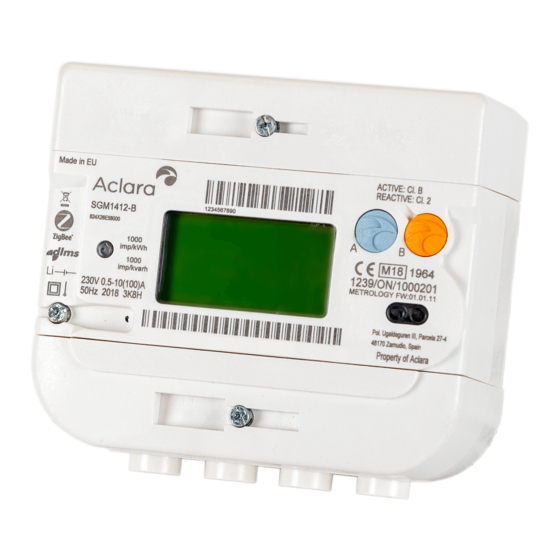
Page 32: Nameplate
Nameplate Nameplate This section describes the various possible markings on the face of the meter. 1) Country of manufacture 9) Class II (double-insulated) 2) WEEE compliance 10) Internal lithium battery 3) Meter model 11) Meter specifications 12) Global Unique Identifier (GUID) 4) ZigBee Smart Energy interoperability number and barcode 5) Meter catalog number... -
Page 33: Csp Communications Hub Interface
Chapter 3 • Physical Components CSP Communications Hub Interface The SGM1400-B Series meter has been designed to be compliant with the DCC intimate communications hub standard. The standard covers both the mechanical and electrical interface for support of a CSP communications hub. Contactors and Relay Terminals The SGM1400-B Series meters are available in a variety of supply disconnect contactor and auxiliary relay configurations. -
Page 34: Magnetic Detection
Magnetic Detection • When the communications hub cover is removed from the meter (Event) • When the communications hub cover is replaced (Event) When a tamper is detected, the corresponding Event Code will be entered into the Fraud Detection Log. For more information on how to access this log, refer to Event Logging and Errors/Alarms on page 48. -
Page 35: Firmware Components
• Minor Revision indicates a new sub-system or other minor release for integration. • Build Number increments with each release to Aclara Product Validation on a given series. The SGM1400-B meter is made up of the firmware components outlined below. -
Page 36: Firmware Specifications
The meter maintains the checksum for calibration and configuration data and checks its integrity after power returns. During the manufacturing process, Aclara stores the resultant calibration data for each meter. For MID certification, calibrated meters were provided to the approved test house for accuracy and other tests as required. -
Page 37: Firmware Upgrade
Chapter 3 • Physical Components All defects and enhancements are tracked and documented through the Aclara SCM system. The customer release notes will include the following information: • Description of all changes, listed by ID • Compatibility information for firmware versions across the solution (e.g.,... -
Page 38: Power Outages
Power Outages The logical devices within the SGM1400-B Series meter will allow specific roles to upgrade specific network elements. For example, Electricity Meter Firmware Update Client may upgrade the E-Meter Firmware. There are unique unicast encryption and authentication keys provided for each role of each logical device, including the Firmware Update Client, when connecting to each logical device within the meter. -
Page 39: Chapter 4: Communications
Chapter 4 • Communications CHAPTER OMMUNICATIONS The SGM1400-B Series meter has been designed to support the industry standard DCC Intimate Communications Hub Interface Specification (ICHIS), which defines the hardware interface for connectivity to CSP sourced communications hubs and the supply levels to provide power to any mating communications hub. The meter also supports a home area network (HAN) that establishes ZigBee protocol connections between two devices, notably an in-home display (IHD) and the communications hub. -
Page 40: 20 Pin Connector
Communication Interfaces 20 Pin Connector Input/ Name Symbol Output Pull-up Function +12 V +12 V – – 12 V DC power supply rail +12 V +12 V – – 12 V DC power supply rail Common – – Common DC power supply rail Common –... -
Page 41: Home Area Network (Han)
Chapter 4 • Communications supply This connection provides line voltage (i.e., 230 V) directly from the un-metered, live supply connection terminal. N - N supply This connects directly to the neutral connection terminal. load This connects directly to the live load main connection of the electricity meter for the use of PLC HAN when a site is disconnected. - Page 42 Communication Interfaces S G M 1 4 0 0 S e r i e s S m a r t M e t e r U s e r M a n u a l – S M E T S 2...
-
Page 43: Chapter 5: Metrology Functionality
Chapter 5 • Metrology Functionality CHAPTER ETROLOGY UNCTIONALITY The SGM1400-B Series meter supports an extensive feature set comprising metrology related functions, support of tariffs, load profile, power quality data, etc. The meter is similar to a complete energy meter (not just an electricity meter) when coupled with appropriate ZigBee communication devices for metering gas. -
Page 44: Frequency Of Supply
Multipurpose Energy Metering Number Instantaneous Measurement Reactive Power Q1 – kVAr (Secondary) Total Reactive Power Q1 – kVAr (Prim+Sec SGM1422-B) Reactive Power Q2 – kVAr (Primary) Reactive Power Q2 – kVAr (Secondary) Total Reactive Power Q2 – kVAr (Prim+Sec SGM1422-B) Reactive Power Q3 –... -
Page 45: Power Quality Measurements
Chapter 5 • Metrology Functionality Number Cumulative Register Total Reactive Import – kWh (Primary) Total Reactive Import – kWh (Secondary) Total Reactive Import – kWh (Prim+Sec SGM1422-B) Total Reactive Export – kWh (Primary) Total Reactive Export – kWh (Secondary) Total Reactive Export – kWh (Prim+Sec SGM1422-B) Reactive Energy Q1 –... -
Page 46: Sag And Swell
Power Quality Measurements The event log will record the time and date stamp for the start and end of the event and the total number of events. Sag and Swell The SGM1400-B Series meters can be configured to identify when voltage sag/swell events have occurred. -
Page 47: Voltage Quality Measurements
Chapter 5 • Metrology Functionality the event log or send an alert to the headend when the threshold parameters for a power factor event are met. The event log shall record the time and date stamp for the start and end of the event and the total number of events. Power factor monitoring on single phase installations is not recommended due to the significant number of alerts generated. -
Page 48: Rms Extreme Under Voltage
Profiles If the RMS voltage returns to a value below the RMS Extreme Over Voltage Threshold longer than the configured measurement period, the meter will generate a corresponding entry in the Power Event Log and send an alert to the HAN interface. -
Page 49: Load Profile
Chapter 5 • Metrology Functionality demand quantities for load profile (LP) and average instrumentation quantities for instrumentation profile (IP). Load Profile Load profile is traditionally configured to record a number of demand quantities (channels) at discrete time intervals (periods). Four load profile channels are supported and are defaulted to the following: •... -
Page 50: Data Storage
Data Storage Data Storage The SGM1400-B Series meter’s data storage includes load profile, instrumentation profile, time-of-use, and block tariff metering. Load Profile By default, the SGM1400-B Series meter can store a minimum of four channels of load profile demand data, at an interval of 30 minutes, for a period of 24 months. The number of channels is reconfigurable. -
Page 51: Block Tariffs
Chapter 5 • Metrology Functionality • 16 day profiles • 5 week profiles • 4 season profiles • 50 special day profiles Block Tariffs There are four block thresholds for each of the eight TOU rates, resulting in a 4x8 price matrix. -
Page 52: Monthly Billing Data
Billing Data • TBC1 - 2 and PB Debt Payments: Last Collection Time • Last Collection Amount • Total Amount Remaining • • Emergency Credit Status • Disconnect Switch Status Primary Element • Each daily data set includes a time and date stamp for when the snapshot occurred. In the event of a power outage over the midnight boundary, the meter will perform the daily billing snapshot once power returns after the midnight boundary. -
Page 53: Asynchronous Billing
Chapter 5 • Metrology Functionality Each set of historical data contains a time and date stamp when the billing reset occurred. The meter will record the source that activated the end of billing period, such as automatic end of month, forced billing reset from the headend system, etc. Asynchronous Billing Asynchronous billings typically occur in the following situations: •... - Page 54 Billing Data S G M 1 4 0 0 S e r i e s S m a r t M e t e r U s e r M a n u a l – S M E T S 2...
-
Page 55: Chapter 6: Advanced Features
Chapter 6 • Advanced Features CHAPTER DVANCED EATURES This chapter provides information on the advanced features of the SGM1400-B, such as supply connection and disconnection, auxiliary load relay, clock, and event and error logging. Supply Disconnect and Reconnect All SGM1400-B Series meters have supply disconnection and reconnection (SDR) functionality. -
Page 56: Load Limiting
Supply Disconnect and Reconnect Load Limiting The SGM1400-B Series meters support automatic disconnection of supply if the delivered power from the network to the customer exceeds a predefined average threshold over a predefined period of time. When this functionality is enabled, the service will be disconnected if the average consumption over the configured period of time exceeds the configured threshold. -
Page 57: Overheating
Chapter 6 • Advanced Features Overheating The overheating event feature is application- and customer-specific. Tamper Detection The SGM1400-B meter has the capability to open the load switch when detecting a tamper condition. Arming and Disarming The SGM1400-B Series meters support a supply arming function to provide a safer means of reconnecting supply to a premise, especially when activating supply remotely. -
Page 58: Event Logging And Errors/Alarms
Event Logging and Errors/Alarms Event Logging and Errors/Alarms The SGM1400-B Series meters continually monitor for conditions that have been configured to be recorded upon occurrence. These events, errors, and alarms can be read locally via the optical port and a supported handheld/laptop device. They can also be read remotely over the AMI system back to the headend or other allowable remote devices. -
Page 59: Credit Object Types
Chapter 6 • Advanced Features The SGM1400-B Series meter family supports a single account for electricity import. Credit Object Types A SGM1400-B Series meter account may include a combination of the following credit object types, depending on the payment mode of operation (Credit or Prepayment): •... -
Page 60: Payment Modes
Prepayment Solution • Payment-based Charge Object: Describes charges that are collected from every top-up (credit payment via UTRN) and put towards debts in repayment. This is a percentage-based charge, where a set portion of the total amount of top-up credit received is taken to pay off that debt (i.e., with every payment, 20% of the payment is applied to the debt amount, thus reducing the amount of debt in this charge). -
Page 61: Prepayment Mode
Chapter 6 • Advanced Features Prepayment Mode In Prepayment mode, the SGM1400-B Series meters utilize the credits and charges detailed below. Credits Token Credit Object (Meter Balance) In Prepayment mode, the meter balance represents the amount of credit the • consumer either currently has available (positive amount) or currently owes (negative amount). -
Page 62: Charges
Prepayment Solution meter balance. If the value is, or falls, below the Disablement Threshold, the supply will be disconnected except under the circumstance that a non-disconnect (friendly disconnect) period is in force. When top-ups are applied, any emergency credit used will be taken from •... -
Page 63: Changing Payment Modes
Chapter 6 • Advanced Features Charges collected for this debt will terminate once the debt has been paid • off. Initial debt and debt recovery rate (amount collected each period) are • configurable. The debt, debt recovery rate, and debt recovery period can be updated at •... -
Page 64: Changing To Credit Mode
Prepayment Solution Changing modes requires a sequence of commands that are governed by a request of the supplier. During a change of mode, the previously configured tariff prices and standing charge will be maintained, but they can optionally be updated before or after the change of mode. -
Page 65: Changing To Prepayment Mode
Chapter 6 • Advanced Features Changing to Prepayment Mode The headend system will send the commands listed below to change the payment mode to Prepayment. Update Prepayment Configuration This command configures the following for use in Prepayment mode: Non-disablement Calendar – Up to 5 day profiles. •... -
Page 66: Non-Disablement
Prepayment Solution Activation of emergency credit with amount (emergency credit limit) as • set in the Update Prepayment Configuration command Manage Debt on the ESME – optional This command is optional and configures the debts and their collection parameters. This command can only be executed once the ESME is in Prepayment mode, and it is used to update the imposed debts on the consumer as determined by the supplier. -
Page 67: Days
Chapter 6 • Advanced Features Days Up to five days can be individually configured to have non-disablement and disablement periods. One is specifically used to define a profile for special days (non-disablement all day), and the other four are used for the week profiles. Only two days which are configured to have non-disablement/disablement periods may be used each week. -
Page 68: Top-Ups
Prepayment Solution Top-Ups Credit top-ups are applied to a consumer account using a unique transaction number (UTRN), sometimes referred to as a ‘token.’ UTRN (Token) Overview The UTRN is constructed from the 19-digit Prepayment Token Decimal (PPTD) appended with a further Check Digit, resulting in a 20-digit UTRN. Prepayment Token Decimal (PPTD) The Prepayment Token Decimal (PPTD) is a 19-digit decimal integer. -
Page 69: Consumer Utrn Token - 20-Digit Decimal
Chapter 6 • Advanced Features Token K Classes Constant Value – Decimal Value – Hex Purpose K_Class MIN Class 0, 1, 2, 3 00 000 000 000 000 000 000 0x0 0000 0000 0000 0000 0_1_ 2_3_MIN token value K_Class MAX Class 0, 1, 2, 3 73 786 976 294 838 206 463 0x3 FFFF FFFF FFFF FFFF 0_1_ 2_3_MAX... -
Page 70: Prepayment Key
Prepayment Solution Prepayment Key The secret 128-bit prepayment key used in the MAC generation and UTRN validation is written to the ESME under the control of the headend system when the Update Security Credentials command is sent. Upon a successful execution of this command, the ESME will reset its internal UTRN counter cache. - Page 71 Chapter 6 • Advanced Features Enter UTRN Menu Options Button Action B Button Press Moves the cursor to the next digit B Button Hold Accepts the current 20-digit UTRN for validation See the images below for display examples. S G M 1 4 0 0 S e r i e s S m a r t M e t e r U s e r M a n u a l – S M E T S 2...
-
Page 72: Utrn Entry Responses
Prepayment Solution UTRN Entry Responses Every entry of a UTRN token will generate a response, whether accepted or rejected, which in turn is logged within the ESME. These responses will either be alerts or events; see Prepayment Events and Alerts on page 64. Successful UTRNs and their top-up amounts are logged in the following billing logs: •... -
Page 73: Maximum Meter Balance
Chapter 6 • Advanced Features The rules for the lockout feature are detailed in the following table. UTRN Token Lockout Conditions Lockout Lockout Counter Reason State Increments, but still < 10 Invalid UTRN entry received. Lockout State is OFF and a valid UTRN entry is received Resets (= 0) OR top-of-the-hour is crossed. -
Page 74: Order Of Recovery Of Debts
Prepayment Solution However, the amount of payment recovery is also limited by the following (whichever is the smallest): • Amount of payment debt remaining • Weekly cap amount remaining Order of Recovery of Debts When a top-up is applied, any outstanding debts are recovered prior to adding any remaining monies to the meter balance. -
Page 75: Prepayment Logs
Chapter 6 • Advanced Features Prepayment Events and Alerts When HAN Device ID (hex) Description Alert Sent Logged Triggered Notification 10 Invalid UTRN Manual Entry UTRN entries 81C4 Yes – Event Log Suspended within Current Hour After 81C5 UTRN Rejected as Locked Out Suspension until Yes –... - Page 76 Prepayment Solution Time-based Debt Registers 1 and 2 – amounts remaining • Accumulated Debt Register • Recorded daily at the end of each day • Depth = 31 • Billing Data – Change of Mode Triggered Data: • Timestamp of snapshot •...
-
Page 77: Prepayment Menu - Display
Chapter 6 • Advanced Features Prepayment Menu – Display In Prepayment mode, the ESME displays a Prepayment menu. This menu allows the consumer to access various prepayment-related quantities such as meter balance, emergency credit balance, etc. Pressing Button B will cycle the display through the various menus, but an additional menu is available in Prepayment mode, as shown in the table below. -
Page 78: Mandatory Prepayment Menu Items
Prepayment Solution Typical Prepayment Menu Structure Item Emergency Credit Status Last Five Credits Accumulated Debt Prepayment-based Debt Time-based Debt Available Credit Debt to Clear Aggregated Debt Enter UTRN Audible Alert Settings Mandatory Prepayment Menu Items Although the Prepayment Item List may be customised by the supplier, the following line items cannot be removed from the list for functionality purposes: •... - Page 79 Chapter 6 • Advanced Features Prepayment Menu Operations Item Upon Selecting Press Button A Press Button B Repeated presses cycle around the following (x = 1 to 5): Last Five Credits – • Credit x Amount Credit 1 Amount Exits Last Five Credits once entered •...
- Page 80 Prepayment Solution S G M 1 4 0 0 S e r i e s S m a r t M e t e r U s e r M a n u a l – S M E T S 2...
-
Page 81: Chapter 7: Installation
Chapter 7 • Installation CHAPTER NSTALLATION The following sections provide basic information for installing a SGM1400-B Series meter by a qualified individual. Terminal Connections The following sections describe and illustrate the terminal connections of each meter in the SGM1400-B Series meter family. Terminal Block The SGM1400-B Series meters have several terminal block configurations. -
Page 82: Sgm1422-B Terminals
Installation Procedures SGM1422-B Terminals The SGM1422-B meter has three line terminals and two neutral terminals. The terminals align horizontally when viewing the meter terminal block at the bottom of the meter (with the exception of the 5 terminal that is located above terminals 3 and 4). - Page 83 Chapter 7 • Installation SGM1415-B SGM1416-B SGM1422-B Attach the terminal cover to the meter and attach seal. The torque value is • 0.6-0.9 Nm. Do not over-tighten the screw. S G M 1 4 0 0 S e r i e s S m a r t M e t e r U s e r M a n u a l – S M E T S 2...
-
Page 84: Installation Screwdrivers
To install the SGM1400-B Series meters, consideration must be given to the type of screw that was defined as part of the meter configuration for manufacturing. Aclara offers support for the following types of screws: • Phillips cross-recessed combination type metal screw •... -
Page 85: Backup Power Supply
Chapter 7 • Installation PZ2 screwdrivers are not recommended for this purpose because damage is likely to be caused to the screw head. Backup Power Supply The SGM1400-B Series meters have an internal backup power battery that is not replaceable in the field. It is designed for a 20 year lifetime. Mounting Template The SGM1400-B Series meters support a three screw mounting arrangement that is typically used on IEC energy meters. - Page 86 Connect SGM1400-B to the CSP Communications Hub After several minutes, the communications hub will connect its wide area network (WAN) to the cellular network. The SW and WAN LEDs will flash every five seconds. The installer initiates a process to pair (connect) the SGM1400-B meter to the communications hub.
- Page 87 Chapter 7 • Installation Use the A and B buttons to enter the correct PIN. Press and hold the button to submit the PIN. Press and hold the button to Join Network. S G M 1 4 0 0 S e r i e s S m a r t M e t e r U s e r M a n u a l – S M E T S 2...
-
Page 88: Notifications To Installers And Utilities
Notifications to Installers and Utilities The meter will now start searching for a network to join. The connection progress will be displayed during the process. Once the meter has successfully joined the communications hub, press the A button to continue. The remaining commands in the installation and commissioning process will be sent to the SGM1400-B meter. - Page 89 The utility should ensure that procedures are in place for the secure disposal of meters that are not to be re-installed or are deemed end of life. For end of life meters that are returned to the factory, Aclara can •...
- Page 90 Notifications to Installers and Utilities Security Credentials Please note, there are no security credentials on the meter that will allow access to any other devices. This meter only contains its own security credentials. Connection to other Devices The meter will only connect to other devices on the HAN. There are no other channels to allow connection.
-
Page 91: Chapter 8: Tests Procedures And Maintenance
Chapter 8 • Tests Procedures and Maintenance CHAPTER ESTS ROCEDURES AND AINTENANCE SGM1400-B Series meters are equipped with a pulse output LED as well as test indicators on the display. Pulse Output LED The SGM1400-B Series meters are equipped with an LED indicator for absolute active energy. -
Page 92: Test Procedures
Test Procedures Test Procedures The following sections describe the requirements and steps for performing various tests. Field Accuracy Test Test mode allows the meter to be tested for accuracy in the field without disturbing any billing data. In order to check the accuracy of the meter in the field, a portable standard and a phantom load generator is required. -
Page 93: Maintenance And Repairs
The SGM1400-B Series meters are factory calibrated and routine maintenance is not required. Because of the high component density of the PC boards and the integrated design, any repairs should be performed by Aclara. Please contact Aclara Support to schedule and return meters for repairs. - Page 94 Disposal S G M 1 4 0 0 S e r i e s S m a r t M e t e r U s e r M a n u a l – S M E T S 2...
-
Page 95: Chapter 9: Specifications
Chapter 9 • Specifications CHAPTER PECIFICATIONS Parameter Specification Single phase, single element (SGM1411-B, SGM1412-B, SGM1415-B, SGM1416-B) Phase / Connection Single phase, dual element (SGM1422-B) Current (I 0.5–10 A (100 A) Voltage Rating -20% to +15% Starting Current 40 mA Frequency 50 Hz ±... - Page 96 Parameter Specification Operating & Storage 95% non-condensing Humidity Enclosure Ingress Protection IP54 (IEC 60529) Insulation Class Protective Class II Dimensions 114 mm H x 130 mm W x 65 mm D SGM1411-B = 500 grams SGM1412-B = 600 grams Weight SGM1415-B = 715 grams SGM1416-B = 720 grams SGM1422-B = 715 grams...
-
Page 97: Catalogue Codes
Chapter 9 • Specifications Catalogue Codes S G M 1 4 0 0 S e r i e s S m a r t M e t e r U s e r M a n u a l – S M E T S 2... - Page 98 Catalogue Codes S G M 1 4 0 0 S e r i e s S m a r t M e t e r U s e r M a n u a l – S M E T S 2...
-
Page 99: Appendix A: Event Codes
Appendix A • Event Codes PPENDIX VENT ODES UK SMETS2 The event codes supported by the SGM1400-B are described in the tables on the following pages. The only distinction between an event and an error/alarm is whether it is filtered to the event log or the error/alarm register. The logs in which a code appears is determined by the filter configuration for each log. - Page 100 UK SMETS2 Mandated / Contains ESIVIE / Critical / Alert Alert Security Event Power ALCS Code Description Enable or Sensitive GSIVIE Remote Party Non-Critical Event Log Event Log Disable Data Alert On Emergency Credit Has Become 0x8119 Non-Critical Mandated Supplier Available (prepayment mode) Failure in changing or maintaining 0x811A...
- Page 101 Appendix A • Event Codes Mandated / Contains ESIVIE / Critical / Alert Alert Security Event Power ALCS Code Description Enable or Sensitive GSIVIE Remote Party Non-Critical Event Log Event Log Disable Data Alert On Supplier and 0x8F34 Supply Enabled after Load Limit Critical Mandated Network Operator...
- Page 102 UK SMETS2 Mandated / Contains ESIVIE / Critical / Alert Alert Security Event Power ALCS Code Description Enable or Sensitive GSIVIE Remote Party Non-Critical Event Log Event Log Disable Data Alert On Device Digital Signing Certificate 0x8F4D Mandated replacement succeeded Device Key Agreement Certificate 0x8F4E Mandated...
- Page 103 Appendix A • Event Codes Mandated / Contains ESIVIE / Critical / Alert Alert Security Event Power ALCS Code Description Enable or Sensitive GSIVIE Remote Party Non-Critical Event Log Event Log Disable Data Alert On Future - date HAN Interface Supplier or WAN 0x8F66 Critical...
- Page 104 UK SMETS2 Mandated / Contains ESIVIE / Critical / Alert Alert Security Event Power ALCS Code Description Enable or Sensitive GSIVIE Remote Party Non-Critical Event Log Event Log Disable Data Alert On RMS Voltage below Extreme Under 0x8095 Non-Critical Mandated Network Operator Voltage Threshold RMS Voltage below Voltage Sag...
- Page 105 Appendix A • Event Codes Mandated / Contains ESIVIE / Critical / Alert Alert Security Event Power ALCS Code Description Enable or Sensitive GSIVIE Remote Party Non-Critical Event Log Event Log Disable Data Alert On Enable or 0x81AE Error Non-Volatile Memory Non-Critical Supplier Disable...
- Page 106 UK SMETS2 Mandated / Contains ESIVIE / Critical / Alert Alert Security Event Power ALCS Code Description Enable or Sensitive GSIVIE Remote Party Non-Critical Event Log Event Log Disable Data Alert On Disablement of Supply (suspended 0x8F83 Non-Critical Mandated Supplier due to insufficient credit) Smart Meter Integrity Issue - Warning 0x81A0...
-
Page 107: Index
Index 4, 6, 10, 16, 20, 81, 85 display 18, 20 configuration active modes 14, 22, 39, 40, 81, 85 energy high energy 26, 33, 39 33, 81, 89 power 14, 22, 35, 39, 40, 81, 85 active tariff apparent terminal 10, 14, 81 direction... - Page 108 Index 24, 31, 45, 71, 85 terminal 9, 71 block contactor 5, 9, 23, 75, 79, 93, 95 cover 23, 71 relay 9, 23 screw terminal layout 7, 8, 73 voltage 5, 47, 82, 85 14, 17 battery 4, 5, 35–37, 46, 90, 93 over 37, 39, 89 4, 5, 35–38, 46, 90...
Need help?
Do you have a question about the SGM1412-B and is the answer not in the manual?
Questions and answers