Table of Contents
Advertisement
Quick Links
Advertisement
Table of Contents

Related Manuals for Aclara RF 3.0 Base Station


Summary of Contents for Aclara RF 3.0 Base Station
- Page 1 Aclara RF 3.0 Base Station Field Guide Y21060-TUM Revision A www.Aclara.com...
- Page 3 Disclaimer The information in this document is subject to change without notice and should not be construed as a commitment by Aclara. Aclara assumes no responsibility for any errors that may appear in this document. No responsibility is assumed for the use or reliability of software on equipment that is not supplied by Aclara.
- Page 4 B a s e S t a t i o n F i e l d G u i d e...
-
Page 5: Table Of Contents
Aclara Contact Information ....36 Aclara Support ..... . 36... -
Page 7: Fcc/Ic Compliance Statement
• 7.1 dBi for 450 – 470 MHz • 8.7 dBi for 901 – 941 MHz Caution: Any changes or modification made to this device without the expressed, written approval of Aclara Technologies LLC may void the user's authority to operate this device. FCC/IC Compliance Statement... -
Page 8: Déclaration De Conformité Fcc/Ic
• Brancher l'appareil dans une prise sur un circuit électrique différent de celui sur lequel le récepteur est branché. • Consultez le revendeur ou un technicien radio/TV expérimenté (Aclara) pour obtenir de l'aide. FCC ID: LLB9985T491 IC: 4546A-9985T491 L'antenne ne doit pas avoir un gain supérieur à: •... -
Page 9: Fcc/Ic Exposure Statement
FCC/IC Exposure Statement Aclara Technologies LLC low power RF devices and their antennas must be fixed-mounted on indoor or outdoor permanent structure(s) providing a separation distance of at least 1.5 meters (about 5 feet) from all persons during normal operation. This device is not designed to operate in conjunction with any other antennas or transmitters. -
Page 10: Guide D'exposition Aux Rf Fcc/Ic
Guide d’exposition aux RF FCC/IC Les appareils RF de faible puissance d'Aclara Technologies LLC et leurs antennes doivent être montés de manière fixe sur une ou plusieurs structures permanentes intérieures ou extérieures offrant une distance de séparation d'au moins 1,5 mètres de toutes les personnes pendant le fonctionnement normal. -
Page 11: Tools And Equipment
Tools and Equipment In addition to standard hand tools, Aclara recommends having the following tools and equipment available when working on the Base Station: • Laptop with Ethernet port • Main board programming interface cable (20 foot Ethernet Cat-6) •... -
Page 12: Safety Guidelines
Only trained personnel should be working on the Base Station. Disconnect all power before working inside the Base Station enclosure. Aclara recommends using ESD grounding protective measures with the installation instructions of most of our products. Equipment ground or earth ground are acceptable for ESD grounding when this information is not available. -
Page 13: Base Station Main Components
Base Station Main Components The Base Station includes RF antennas and a protective enclosure containing Base Station electronics and a rechargeable battery. RF Antenna A Base Station RF antenna is a separate component connected to the protective Base Station enclosure via coaxial cable. The cable required varies depending on the location of the installation. -
Page 14: Routine Visual Checks
Routine Visual Checks To avoid injury to oneself and damage to the Base Station system, use proper safety techniques when working inside the Base Station enclosure. Do not touch or allow metal objects to touch battery or AC components of the Base Station assembly. High voltage hazard. -
Page 15: Base Station Interior
Antenna Front End Module (FEM) 450 MHz FEM inside Quadplexer 900 MHz FEM against wall T-Boards (3x450 MHz & 1x900 MHZ Main Board Fiber Module Aclara Power Converter (APC) Surge Protective Door Switch LiFePO4 Battery Device (SPD) Base Station Interior... -
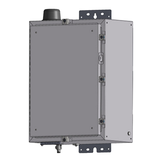
Page 16: Base Station Enclosure Door
Base Station Enclosure Door Open the Base Station enclosure by loosening the 1/4”-20 clamp screws with a socket wrench or slotted screwdriver. 2. Reverse the procedure to secure the enclosure door. Tighten each clamp screw until each clamp is fully seated against the enclosure frame. -
Page 17: Power Disconnect
Power Disconnect Disconnect AC power feeding the Base Station before servicing. The following instructions describe how to disconnect the AC power from electronics cabling, but it is critical to know that 120 VAC enters the box via the surge protector and remains live in the box even if you disconnect power into the battery controller. -
Page 18: Battery Removal
11.. 2. Open the enclosure by loosening the 3/8” slotted hex bolts. See page 10. 3. Disconnect the battery cables from the Aclara Power Converter (APC). The battery cables plug into the port identified as Battery on the APC. - Page 19 9. Raise the black insulated cover and battery strap away from the positive (+) terminal side of the battery. 10. Remove the black wire from the negative (-) terminal battery post and then the red wire from the positive (+) terminal battery post using a 10mm insulated torque wrench.* Batteries must be disposed of according to national and local ordinances.
-
Page 20: Battery Installation
Battery Installation Note: To avoid damaging some components, make all antenna connections before connecting power. Connect the red wire to the positive (+) terminal. 2. Connect the black wire to the negative (-) terminal. 3. Tighten the battery lugs to 60 inch-pounds using a 10mm insulated torque wrench. - Page 21 5. Reinstall the battery heater assembly strap and tighten with a #2 Phillips screwdriver. 6. Reinstall the insulation cover. 7. Plug the Batt/Can wires int the port labeled Batt/Can on the APC. 8. Plug the battery cables into the port labeled Battery on the APC.
-
Page 22: Laird Antenna Cable Removal/Replacement
dbSpectra Antenna Cable Removal/ Replacement Disconnect the power feeding the Base Station. See page 11. Open the enclosure by loosening the 1/4”-20 clamp screws. See page 10. Remove any cable ties securing antenna cable. Remove the tape from the RF antenna connectors. Disconnect the antenna cable from the bottom of the Base Station and the antenna base. - Page 23 Cover the entire connector of each antenna cable connection with a half-lapped layer of electrical tape, beginning just below the shrink wrap and wrapping from bottom to top. Note: This layer should be applied with the adhesive side out for easy removal. Layer half-lapped mastic tape over the electrical tape, wrapping from bottom to top.
-
Page 24: Laird Rf Antenna Base Removal/Replacement
Laird RF Antenna Base Removal/ Replacement Disconnect power connector from the PCB enclosure. See page 11. Note: The Front End Module (FEM) can be damaged if antennas are not connected while the Base Station is powered. Remove tape from RF antenna connector. Disconnect cable connector from RF antenna. -
Page 25: Cellular Antenna Removal/Replacement
Cellular Antenna Removal/ Replacement Disconnect AC power from the Base Station. See page 11.. Open the enclosure by removing the 1/4”-20 clamp screws. See page 10. Remove M-20 nut and washer that secure antenna to Base Station cabinet. Grasp cellular antenna on top of Base Station unit, then turn it to the left to loosen. -
Page 26: Printed Circuit Board (Pcb) Removal/Replacement
• Use ESD protective wrist straps at all times when handling ESD sensitive assemblies, such as the PCB assemblies, to help ensure the continued performance of Aclara products. • Discharge static on yourself by touching a metal object before unpacking or touching the PCBs or other Base Station components. - Page 27 Note: For more information on proper ESD handling, please refer to Guidelines for Handling Electrostatic Discharge Sensitive Components (Y20217-TEB). Disconnect easily accessible cables connected to the main board. Loosen but do not remove the four #8-32 KEPS nuts holding the main board bracket to the enclosure wall using a deep well, 11/32”...
- Page 28 Close and secure the Base Station door. Remove the ESD strap from your wrist and the Base Station ground lug. Restore power to the Base Station enclosure. Printed Circuit Board (PCB) Removal/Replacement...
-
Page 29: T-Board Removal/Replacement
T-Board Removal/Replacement Disconnect power from the Base Station cabinet. See page 11. Open the Base Station enclosure door. See page 10. Place ESD grounding strap on your wrist and tighten. Then connect opposite end of wire to the ground lug on the Base Station cabinet. - Page 30 Remove the ESD strap from your wrist and from the Base Station ground lug. Restore power to the Base Station enclosure. Note: Use the ESD protective bag from the new board to protect the old board when returning it to Aclara. Printed Circuit Board (PCB) Removal/Replacement...
-
Page 31: Front End Module (Fem) Removal/Replacement
Front End Module (FEM) Removal/ Replacement Disconnect power from the Base Station cabinet. See page 11. Open Base Station enclosure door. See page 10. Loosen but do not remove the four #8-32 KEPS nuts holding the FEM bracket to the enclosure wall using a deep well, 11/ 32”... - Page 32 Place the new main board bracket subassembly over the four #8-32 KEPS nuts on the enclosure wall and slide it down. Tighten the four #8-32 KEPS nuts. Close and secure the Base Station door. Restore power to the Base Station enclosure. Front End Module (FEM) Removal/Replacement...
-
Page 33: Aclara Power Converter (Apc) Removal/Replacement
Place the new APC over the four #8-32 KEPS nuts on the back panel and slide it down. Tighten the four #8-32 KEPS nuts. Connect any cables removed from the old APC to the new APC. Aclara Power Converter (APC) Removal/Replacement... - Page 34 Close and secure the Base Station door. Restore power to the Base Station enclosure. Aclara Power Converter (APC) Removal/Replacement...
-
Page 35: Fiber Module Removal/Replacement
Fiber Module Removal/Replacement Disconnect power from the Base Station cabinet. See page 11. Open the Base Station enclosure door. See page 10. Disconnect the fiber module power cable and Ethernet cable from the main board. Loosen but do not remove the two #8-32 KEPS nuts holding the fiber module assembly to the enclosure wall using a deep well 11/32”... - Page 36 Connect the cables disconnected in Step 6 to the new fiber module. Place the fiber module subassembly on the two #8-32 KEPS nuts on the enclosure wall and slide it towards the bottom of the enclosure. Tighten the two #8-32 KEPS nuts. Connect the fiber module power cable and the Ethernet cable from the main board to the new fiber module.
-
Page 37: Quadplexer Removal/Replacement
Quadplexer Removal/Replacement Disconnect power from the Base Station cabinet. See page 11. Open the Base Station enclosure door. See page 10. Remove the splitter bracket from the Quadplexer by removing the #8-32 stainless steel screw with a #2 Phillips screwdriver. Remove the routing clips from the Quadplexer by removing the #8-32 stainless steel screws with a #2 Phillips screwdriver. - Page 38 Remove the Quadplexer bracket by removing the #8-32 stainless steel flathead screws with a #2 Phillips screwdriver. Attach the Quadplexer bracket to the new Quadplexer using the #8-32 stainless steel flathead screws and #2 Phillips screwdriver used in the previous step. Connect the cables removed in Step 7 to the new Quadplexer.
-
Page 39: Base Station Commissioning Hardware Setup Laptop Ethernet Connection
Base Station Commissioning Hardware Setup Laptop Ethernet Connection Connect the Ethernet cable to laptop and main board. 2. Open a web browser on the laptop. https:// 3. Access the local user interface by typing 192.168.8.20:8080 in the web browser’s address bar. 4. -
Page 40: Investigation Inside The Base Station Enclosure
Investigation Inside the Base Station Enclosure Note: Use ESD procedures when handling PCBs. Verify the following: • PCB LEDs are properly illuminated (refer to specific PCB troubleshooting for LED function description). • Cable connections are not damaged, intact, and securely tightened. -
Page 41: Troubleshooting
Troubleshooting It is important to know the battery state-of-charge varies by season and latitude. Checking the Base Station Battery With a laptop properly connected to the Static IP Ethernet port of the Base Station, verify the battery is connected, charging, and communicating with the battery controller. -
Page 42: Base Station Support And Returns
Aclara Contact Information Aclara Technologies LLC 30400 Solon Road Solon, Ohio 44139 Phone: 800-892-9008 Email: Aclarasupport@hubbell.com Aclara Support For additional questions or support, contact Aclara via email Aclarasupport@hubbell.com or call 1-800-892-9008. Aclara Returns To return product, email AclaraRMA@hubbell.com or call 1-800- 892-9008.
Need help?
Do you have a question about the RF 3.0 Base Station and is the answer not in the manual?
Questions and answers