
Related Manuals for Aclara SGM1430-B


Summary of Contents for Aclara SGM1430-B
- Page 1 SGM1430-B Smart Meter Polyphase User Manual - SMETS2 Y20995-TUM Revision A www.Aclara.com...
- Page 3 Disclaimer The information in this document is subject to change without notice and should not be construed as a commitment by Aclara. Aclara assumes no responsibility for any errors that may appear in this document. No responsibility is assumed for the use or reliability of software on equipment that is not supplied by Aclara.
- Page 4 S G M 1 4 3 0 - B S m a r t M e t e r P o l y p h a s e U s e r M a n u a l – S M E T S 2...
- Page 5 IEC 62056-21:2002 Hardware Description for local meter data exchange The SGM1430-B smart meter complies with the general requirements of EN 50470 Parts 1 and Parts 3 and also complies with Class M2 Mechanical environment. S G M 1 4 3 0 - B S m a r t M e t e r P o l y p h a s e U s e r M a n u a l – S M E T S 2...
- Page 6 It does not relieve the user of responsibility to use sound practices in application, installation, operation, and maintenance of the equipment purchased. Aclara reserves the right to make changes in the specifications shown herein or to make improvements at any time without notice or obligations. Should...
- Page 7 • trained in rendering first aid. Any work on or near energized meters, meter sockets, or other metering equipment presents the danger of electrical shock. All work on these products must be performed by qualified industrial electricians and metering specialists only.
- Page 8 S G M 1 4 3 0 - B S m a r t M e t e r P o l y p h a s e U s e r M a n u a l – S M E T S 2...
-
Page 9: Table Of Contents
Chapter 1: Introduction Aclara Support ........1 Chapter 2: Product Description General Information . - Page 10 Table of Contents Memory........23 Firmware .
- Page 11 Table of Contents Chapter 6: Advanced Features Supply Disconnect and Reconnect ......43 Supply Contactor Visual Status ......43 Scheduled Disconnection/Reconnection .
- Page 12 Mounting Template ....... . .72 Connect SGM1430-B to the CSP Communications Hub ....72 Notifications to Installers and Utilities.
-
Page 13: Chapter 1: Introduction
The purpose of this document is to provide qualified metering personnel with product description; operating, maintenance, and upgrading instructions; site analysis guides; and diagrams for the SGM1430-B smart meter family. It is not intended to replace the extensive training necessary to install or remove meters from service. - Page 14 Aclara Support S G M 1 4 3 0 - B S m a r t M e t e r P o l y p h a s e U s e r M a n u a l – S M E T S 2...
-
Page 15: Chapter 2: Product Description
The SGM1430-B meter from Aclara is an advanced modular designed family of products for small to medium enterprise and commercial installations. The SGM1430-B is available in a number of different polyphase variants, and it forms an integral part of a complete two-way, secure, end-to-end solution. -
Page 16: General Information
Designed with installation in mind, the SGM1430-B meter offers a means for a quick and secure deployment. A custom-designed LCD provides added value information. For example, when ZigBee is used, information such as HAN pairing progress, notification of pairing complete, local signal strengths for HAN, etc. -
Page 17: Features
• 31 Daily Billing Sets • 16 Day Profiles Features The SGM1430-B smart meter family has the following main features: • Processor internal memory with 1.5 MB of flash memory for program and boot, plus 640 KB of internal RAM... -
Page 18: Models
• Tamper detection for meter cover, terminal cover, and communications hub cover Models The SGM1430-B smart meter family is made up of meters of common physical characteristics and functionality. The nomenclature of the meter models indicates the following: The following models are currently available in the SGM1430-B smart meter... -
Page 19: Terminal Arrangements
Chapter 2 • Product Description Terminal Arrangements The SGM1430-B polyphase meters conform to the British Standard Institute code of practice (BS 7856:2013). SGM1431-B SGM1432-B SGM1433-B S G M 1 4 3 0 - B S m a r t M e t e r P o l y p h a s e U s e r M a n u a l – S M E T S 2... - Page 20 Terminal Arrangements S G M 1 4 3 0 - B S m a r t M e t e r P o l y p h a s e U s e r M a n u a l – S M E T S 2...
-
Page 21: Chapter 3: Physical Components
Chapter 3 • Physical Components CHAPTER HYSICAL OMPONENTS The SGM1430-B smart meter family comprises of a number of polyphase variants with and without 2 A aux relay outputs. The main physical features of a SGM1430-B meter are shown below. Enclosure and Covers The SGM1430-B meters use a thermally stable, UV-protected polycarbonate enclosure that is double insulated to protective Class II. -
Page 22: Display
As a manufacturing option, the meter can also be supplied with an ultrasonic permanent seal. Display The SGM1430-B meter provides a backlit Liquid Crystal Display (LCD) located on the meter face. The display consists of graphical elements and segments. The graphical section displays the meter status in quantities up to eight digits, including the unit of measure. -
Page 23: Descriptor, Numerical, And Unit Indicators
The top line descriptor supports 32 characters. The numerical line supports up to eight digits along with a decimal and other separators. The unit indicator is always to the right of the numerical line. The following items are available for display on the SGM1430-B meter variants. SGM1430-B Variants - LCD Items Supported... - Page 24 Display SGM1430-B Variants - LCD Items Supported SGM1431-B / SGM1432-B / Description in SGM1430-B Manual SGM1433-B Current (I) - Ph1 Current (I) - Ph2 Current (I) - Ph3 Voltage (V) - Ph1 Voltage (V) - Ph2 Voltage (V) - Ph3...
-
Page 25: Active Elements
Chapter 3 • Physical Components SGM1430-B Variants - LCD Items Supported SGM1431-B / SGM1432-B / Description in SGM1430-B Manual SGM1433-B Segment Test Meter Serial Number (YYM1234567) Meter Balance (£) Standing Charge (p) MPAN Customer Identification Number (CIN) Energy Supplier Contact Details:... -
Page 26: Current Status
Display Current Status The four arrows represent the current flow of the meter. The current flow of the meter is portrayed as follows: Horizontal Arrows The horizontal arrows indicate the direction of the flow of active energy. When is illuminated, energy is being consumed from the grid. When is illuminated, energy is being generated at the premise and received by the network. -
Page 27: Han Signal Status
Chapter 3 • Physical Components If the Reverse Run icon is visible, reverse energy has been detected. The reverse run indication can only be cleared by a command via one of the communications ports. The reverse run icon is enabled by setting the appropriate bit in the COSEM error register filter;... -
Page 28: Load Control Relay
Phase The phase indicator L1 indicates the presence of phase voltage above a defined threshold. (The L2 and L3 indicators are unused in the polyphase SGM1430-B meter.) SGM1432-B/SGM1433-B LCD Icons - Contactor and Aux Relay Battery This icon indicates low backup battery voltage. -
Page 29: Warning
Chapter 3 • Physical Components Warning The warning icon indicates a warning condition has been detected by the meter. Display Modes The SGM1430-B meter supports eight different display modes for the UK: • Primary • Alternate 1 • Alternate 2 •... -
Page 30: Manual Operation Timeout
Display Manual Operation Timeout This setting defines the inactivity period for the manual-scroll mode. While operating in manual-scroll mode, if no buttons are pressed, the display will revert back to auto-scroll mode. Default 10 seconds Minimum 1 second Maximum 60 seconds Backlight Timeout This setting defines the period of time the backlight will remain lit following an action which triggered the illumination. -
Page 31: Number Of Digits
Chapter 3 • Physical Components Number of Digits This specifies the number of digits to display when leading zeros are enabled. Default Minimum Maximum Number of Decimal Places This specifies the number of decimal places to display, Default Minimum Maximum Additional Information This specifies the additional information for the following unique display items. -
Page 32: Push Button B - Sealable
Disabled Enabled Optical Port The SGM1430-B meter has an optical port for local communication. It supports the IEC 62056-21 optical communication interface standard with a baud rate of 9,600 bps. The optical port is disabled on meters deployed in field. -
Page 33: Led Indicator
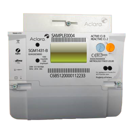
Chapter 3 • Physical Components LED Indicator The LED indicator flashes when measuring the consumer’s load. The LED as default will flash to indicate forward and reverse kWh but can be reconfigured to show kVArh. Nameplate This section describes the various possible markings on the face of the meter. 1) Country of manufacture 9) Class II (double-insulated) 2) WEEE compliance... -
Page 34: Csp Communications Hub Interface
16) Customer serial number & barcode CSP Communications Hub Interface The SGM1430-B meter has been designed to be compliant with the DCC intimate communications hub standard. The standard covers both the mechanical and electrical interface for support of a CSP communications hub. -
Page 35: Magnetic Detection
Codes on page 85 for details on ordering this variant. Memory Processor Internal Memory The SGM1430-B meters have 1.5 MB of flash memory for program and boot as well as 640 KB of internal RAM. External Serial Flash Memory The SGM1430-B meters have 16 MB of external serial flash memory for configuration and operational data as well as for firmware upgrade image storage. -
Page 36: Firmware Components
The SGM1430-B meter is made up of the firmware components outlined below. S G M 1 4 3 0 - B S m a r t M e t e r P o l y p h a s e U s e r M a n u a l – S M E T S 2... -
Page 37: Firmware Specifications
Application The meter firmware application can be upgraded via firmware over-the-air. Firmware Specifications The SGM1430-B meters have two main processors: the metrology processor and the application processor. The metrology processor provides the real-time clock and the measurement and calculation of energy values. The application processor provides functionality such as load profile and time-of-use, relay control, communications support, and Smart Energy Profile. -
Page 38: Firmware Release Notes Process
Firmware release notes will be provided to the customer. The release note details are generated from the Aclara software configuration management (SCM) system. All defects and enhancements are tracked and documented through the Aclara SCM system. The customer release notes will include the following information: •... -
Page 39: Power Outages
The logical devices within the SGM1430-B meter will allow specific roles to upgrade specific network elements. For example, Electricity Meter Firmware Update Client may upgrade the E-Meter Firmware. - Page 40 Power Outages S G M 1 4 3 0 - B S m a r t M e t e r P o l y p h a s e U s e r M a n u a l – S M E T S 2...
-
Page 41: Chapter 4: Communications
Chapter 4 • Communications CHAPTER OMMUNICATIONS The SGM1430-B meter has been designed to support the industry standard DCC Intimate Communications Hub Interface Specification (ICHIS), which defines the hardware interface for connectivity to CSP sourced communications hubs and the supply levels to provide power to any mating communications hub. -
Page 42: 20-Pin Connector
Communication Interfaces 20-Pin Connector Input/ Name Symbol Output Pull-up Function +12 V +12 V – – 12 V DC power supply rail +12 V +12 V – – 12 V DC power supply rail Common – – Common DC power supply rail Common –... -
Page 43: Home Area Network (Han)
Care should be taken when the meter is powered up and the communications module removed from the meter. The AC pins are no longer populated on the SGM1430-B family of products. This is specifically attributed to meters that are deemed RF noise compliant against the latest version of ICHIS V2.1. - Page 44 Communication Interfaces S G M 1 4 3 0 - B S m a r t M e t e r P o l y p h a s e U s e r M a n u a l – S M E T S 2...
-
Page 45: Chapter 5: Metrology Functionality
(not just an electricity meter) when coupled with appropriate ZigBee communication devices for metering gas. Multipurpose Energy Metering The SGM1430-B meter supports the storage and operation of multiple energy types that are measured directly by the meter. Electrical observables are measured directly by the meter. -
Page 46: Frequency Of Supply
Instantaneous Measurement Power Factor Phase Angle Frequency of Supply The SGM1430-B meter supports measurement of the frequency of the main supply. Cumulative Registers The SGM1430-B meter supports the following cumulative observables for each measuring element as well as total. The data is internally stored in milliunits. -
Page 47: Over Current
Over Current The SGM1430-B meter has a configurable over current threshold and duration (in seconds) to activate the event. The event log will record the time and date stamp for the start and end of the event and the total number of events. -
Page 48: Under Voltage Threshold
Voltage Quality Measurements Threshold, the meter generates an event in the Power Event Log and also sends an alert via the HAN. Under Voltage Threshold Upon detecting that the value calculated for phase [n] is below the Phase [n] Average RMS Under Voltage Threshold, the meter will increment the Phase [n] Average RMS Under Voltage Counter, update the Power Event Log, and send an alert via the HAN. -
Page 49: Supply Outage Reporting
UTC date and time of interruption and restoration. Profiles The SGM1430-B meter supports non-volatile recording of two profiles of a number of quantities (channels) at discrete time intervals (periods). These two profiles are:load profile (profile 1) and voltage profile (profile 2). -
Page 50: Interval Time Changes
Load Profile By default, the SGM1430-B meter can store a minimum of four channels of load profile demand data, at an interval of 30 minutes, for a period of 24 months. The number of channels is reconfigurable. For example, the meter memory can store ten channels of load profile energy data, at an interval of 30 minutes, but only for a maximum period of 210 days (7 months). -
Page 51: Time-Of-Use (Tou)
Daily Billing Data The SGM1430-B meter stores 31 daily billing data sets before overwriting occurs. The snapshot will automatically occur on the crossover of the midnight boundary. -
Page 52: Monthly Billing Data
The Daily Billing Snapshot feature can be enabled or disabled through configuration. Monthly Billing Data The SGM1430-B meter stores 13 end-of-billing data sets before overwriting occurs. The billing period is specified monthly. The end-of-month billing date can be specified as the last day of the month or a date specified for each month. -
Page 53: Asynchronous Billing
Chapter 5 • Metrology Functionality Last Collection Amount • Total Amount Remaining • • Emergency Credit Status • Disconnect Switch Status Primary Element • Each set of historical data contains a time and date stamp when the billing reset occurred. The meter will record the source that activated the end of billing period, such as automatic end of month, forced billing reset from the headend system, etc. - Page 54 Billing Data S G M 1 4 3 0 - B S m a r t M e t e r P o l y p h a s e U s e r M a n u a l – S M E T S 2...
-
Page 55: Chapter 6: Advanced Features
The SGM1430-B meters support a definition of a series of relay state change instructions for changing the state of any of the meter relays on a schedule. Automatic Disconnection/Reconnection The SGM1430-B meters support multiple methods by which the supply relay can be automatically disconnected and subsequently reconnected. -
Page 56: Load Limiting
Under/Over Frequency The SGM1430-B meters support disconnection of service if the supply frequency goes above an upper limit or below a lower limit. When this functionality is enabled, the contactor will be disconnected for a defined period of time if the average frequency over a configured period of time exceeds either of the configured thresholds. -
Page 57: Tamper Detection
Chapter 6 • Advanced Features Tamper Detection The SGM1430-B meter has the capability to open the load switch when detecting a tamper condition. Arming and Disarming The SGM1430-B meters support a supply arming function to provide a safer means of reconnecting supply to a premise, especially when activating supply remotely. -
Page 58: Event Logs
Refer to Event Codes on page 87 for a complete list. Event Logs As events are raised, they are filtered into a series of event logs based on the configuration of the meter. The SGM1430-B meter supports the following event logs: Description Event Log This is used to log standard or general events. -
Page 59: Credit Object Types
Chapter 6 • Advanced Features The SGM1430-B meter family supports a single account for electricity import. Credit Object Types A SGM1430-B meter account may include a combination of the following credit object types, depending on the payment mode of operation (Credit or Prepayment): •... -
Page 60: Payment Modes
(time-based tariff charge) or a block tariff (consumption-based tariff charge). A price per unit is assigned to each subdivision of the consumed energy register. Payment Modes The SGM1430-B meter family can operate in one of the two following payment modes: • Credit Mode • Prepayment Mode... -
Page 61: Prepayment Mode
Chapter 6 • Advanced Features Prepayment Mode In Prepayment mode, the SGM1430-B meters utilize the credits and charges detailed below. Credits Token Credit Object (Meter Balance) In Prepayment mode, the meter balance represents the amount of credit the • consumer either currently has available (positive amount) or currently owes (negative amount). -
Page 62: Charges
Prepayment Solution meter balance. If the value is, or falls, below the Disablement Threshold, the supply will be disconnected except under the circumstance that a non-disconnect (friendly disconnect) period is in force. When top-ups are applied, any emergency credit used will be taken from •... -
Page 63: Changing Payment Modes
• Changing Payment Modes SGM1430-B meters with firmware 7.6.0 and later will be supplied with a default of Credit mode. Also, consumption charges (tariff prices) or standing charges will not be set up - they will contain zero charge values. The headend system must set up these charges as part of the initial installation and commissioning process. -
Page 64: Changing To Credit Mode
Prepayment Solution During a change of mode, the previously configured tariff prices and standing charge will be maintained, but they can optionally be updated before or after the change of mode. When prompted to change the payment mode, the electricity smart metering solution (ESME) records a snapshot (maximum of 12 entries that rollover on a first in, first out basis) of the following data that can be read by the headend system:... - Page 65 Chapter 6 • Advanced Features Non-disablement Calendar – Up to 5 day profiles. • Non-disablement Special Days – Maximum of 20 specific dates where • non-disablement is active all day (e.g., Xmas Day and Boxing Day). Maximum Meter Balance – A parameter to limit the maximum amount of •...
-
Page 66: Non-Disablement
Prepayment Solution Prepayment mode, and it is used to update the imposed debts on the consumer as determined by the supplier. This command can be used to update the following parameters: Time-based Debt 1 • Debt recovery amount and scalar with respect to whole currency (e.g., •... -
Page 67: Weeks
Chapter 6 • Advanced Features Weeks Two week profiles are available, and each of these can be configured using two day profiles. Seasons Three seasons can be configured as specified by date ranges, where each season can have two week profiles. Special Days - Holidays As well as the periods defined in the previous section, whole days can be specified as friendly credit holidays –... -
Page 68: Prepayment Token Decimal (Pptd)
Prepayment Solution Prepayment Token Decimal (PPTD) The Prepayment Token Decimal (PPTD) is a 19-digit decimal integer. The most significant two digits of the PPTD are between 73 and 96, this being the result of the addition of 7,394,156,990,786,306,048 (the K-Class 5 Offset) to the decimal representation of the binary Prepayment Top-up Token (PTUT) to distinguish it from other standard transfer specification (STS) defined tokens. -
Page 69: Consumer Utrn Token - 20-Digit Decimal
Chapter 6 • Advanced Features Token K Classes Constant Value – Decimal Value – Hex Purpose K_Class_5_MAX 96 999 999 999 999 999 999 0x5 4225 3A12 6CE3 FFFF MAX Class 5 token value K_Class_6_MIN 97 000 000 000 000 000 000 0x5 4225 3A12 6CE4 0000 MIN Class 6 token value 0x5 6BC7 5E2D 630F K_Class_6_MAX 99 999 999 999 999 999 999 MAX Class 6 token value... -
Page 70: Prepayment Key
Prepayment Solution Prepayment Key The secret 128-bit prepayment key used in the MAC generation and UTRN validation is written to the ESME under the control of the headend system when the Update Security Credentials command is sent. Upon a successful execution of this command, the ESME will reset its internal UTRN counter cache. - Page 71 Chapter 6 • Advanced Features S G M 1 4 3 0 - B S m a r t M e t e r P o l y p h a s e U s e r M a n u a l – S M E T S 2...
-
Page 72: Utrn Entry Responses
Prepayment Solution UTRN Entry Responses Every entry of a UTRN token will generate a response, whether accepted or rejected, which in turn is logged within the ESME. These responses will either be alerts or events; see Prepayment Events and Alerts on page 61. Successful UTRNs and their top-up amounts are logged in the following billing logs: •... -
Page 73: Maximum Credit Threshold
Chapter 6 • Advanced Features Maximum Credit Threshold The maximum credit threshold is the absolute maximum amount of credit from a single transaction that is allowed to be added to the meter. If a top-up via a UTRN exceeds this vend amount, an invalid response will be generated, and the UTRN token will be rejected. - Page 74 Prepayment Solution MB ≥ Meter Balance, EMB ≥ Emergency Credit Balance. UTRN-related events and alerts are highlighted. Prepayment Events and Alerts When HAN Device ID (hex) Description Alert Sent Logged Triggered Notification Combined Credit below Low MB + EMB < 810D Credit Threshold Threshold...
-
Page 75: Prepayment Logs
Chapter 6 • Advanced Features Prepayment Events and Alerts When HAN Device ID (hex) Description Alert Sent Logged Triggered Notification Credit is now > Disablement 8F32 Supply Armed Threshold or ECS44 Update Security Credentials Yes – Security 8F70 Update Security Credentials command Successfully Processed... -
Page 76: Prepayment Menu - Display
Prepayment Solution Time-based Debt Register 2 • Accumulated Debt Register • Recorded upon change of mode • Depth = 12 • Billing Data – Debt Payments Data: • Timestamp of snapshot • Payment made towards debt recovery • Recorded upon every successful payment (processing of UTRN) where •... -
Page 77: Mandatory Prepayment Menu Items
Chapter 6 • Advanced Features Sequencing Configurable Comments Alt4 Menu Yes – up to 50 items Visible when > 0 entries No (signal strength of HAN Signal Strength Always visible (dBm)) Active TOU No (currently active TOU rate) Always visible ... -
Page 78: Prepayment Menu - Item Structure And Access
Prepayment Solution Prepayment Menu – Item Structure and Access The table below outlines the features and navigation of the Prepayment menu. Prepayment Menu Operations Item Upon Selecting Press Button A Press Button B Meter Balance Balance Value Next Prepayment Item Exits Prepayment Menu Emergency Credit Balance Emergency Credit... - Page 79 Chapter 6 • Advanced Features Prepayment Menu Operations Item Upon Selecting Press Button A Press Button B Available Credit on Meter: Available Credit Meter Balance + Emergency Next Prepayment Item Exits Prepayment Menu Credit Balance (if activated) The Minimum Amount to pay to Clear the Debt Debt to Clear accrued on the ESME -...
- Page 80 Prepayment Solution S G M 1 4 3 0 - B S m a r t M e t e r P o l y p h a s e U s e r M a n u a l – S M E T S 2...
-
Page 81: Chapter 7: Installation
Installation Procedures UK Installation To install the SGM1430-B meters, make sure that the following minimum installation steps are performed: Perform specific safety and work area analysis. S G M 1 4 3 0 - B S m a r t M e t e r P o l y p h a s e U s e r M a n u a l – S M E T S 2... - Page 82 Take the last meter read on the existing meter and de-energize all live meter circuits. Remove the old meter for recycling. Assess wall or panel space available for the SGM1430-B meter. Prepare all incoming wire cables for connection to the meter. Take care to specifically identify neutral conductors and check the integrity of conductors.
-
Page 83: Installation Screwdrivers
Installation Screwdrivers To install the SGM1430-B meters, consideration must be given to the type of screw that was defined as part of the meter configuration for manufacturing. Aclara offers support for the following types of screws: •... -
Page 84: Backup Power Supply
PZ2 screwdrivers are not recommended for this purpose because damage is likely to be caused to the screw head. Backup Power Supply The SGM1430-B meters have an internal backup power battery that is not replaceable in the field. It is designed for a 20-year lifetime. Mounting Template The SGM1430-B meters support a three-screw mounting arrangement that is typically used on IEC energy meters. - Page 85 (WAN) to the cellular network. The SW and WAN LEDs will flash every five seconds. The installer initiates a process to pair (connect) the SGM1430-B meter to the communications hub. The DSP sends the SGM1430-B meter credentials to the communications hub, and the HAN LED will flash every 5 seconds when the credentials have been added to the device log.
- Page 86 Connect SGM1430-B to the CSP Communications Hub Use the A and B buttons to enter the correct PIN. Press and hold the button to submit the PIN. Press and hold the button to Join Network. S G M 1 4 3 0 - B S m a r t M e t e r P o l y p h a s e U s e r M a n u a l – S M E T S 2...
-
Page 87: Notifications To Installers And Utilities
A button to continue. The remaining commands in the installation and commissioning process will be sent to the SGM1430-B meter. Typically, the meter will be configured using the Electricity Meter Commissioning Service Requests. The exact order and sequence of the service requests is dependent on the individual energy supplier. - Page 88 4.The utility should ensure that procedures are in place for the secure disposal of meters that are not to be re-installed or are deemed end of life. For end of life meters that are returned to the factory, Aclara can •...
- Page 89 PIN. Removal of the Terminal Cover In some versions of the SGM1430-B, the meter terminal cover contains a retention clip that helps to secure the terminal cover in place. To remove the terminal cover, first remove the terminal cover seal and loosen the terminal sealing screw.
- Page 90 Notifications to Installers and Utilities S G M 1 4 3 0 - B S m a r t M e t e r P o l y p h a s e U s e r M a n u a l – S M E T S 2...
-
Page 91: Chapter 8: Tests Procedures And Maintenance
Chapter 8 • Tests Procedures and Maintenance CHAPTER ESTS ROCEDURES AND AINTENANCE SGM1430-B meters are equipped with two pulse output LEDs as well as test indicators on the display. Pulse Output LED The SGM1430-B meters are equipped with LED indicators for absolute active and reactive energy. -
Page 92: Test Procedures
Test Procedures Test Procedures The following sections describe the requirements and steps for performing various tests. Field Accuracy Test Test mode allows the meter to be tested for accuracy in the field without disturbing any billing data. In order to check the accuracy of the meter in the field, a portable standard and a phantom load generator is required. -
Page 93: Maintenance And Repairs
Heavily filtered inputs may require longer test times.) Maintenance and Repairs The SGM1430-B meters are factory calibrated and routine maintenance is not required. Because of the high component density of the PC boards and the integrated design, any repairs should be performed by Aclara. Please contact Aclara Support to schedule and return meters for repairs. - Page 94 Disposal S G M 1 4 3 0 - B S m a r t M e t e r P o l y p h a s e U s e r M a n u a l – S M E T S 2...
-
Page 95: Chapter 9: Specifications
Chapter 9 • Specifications CHAPTER PECIFICATIONS Parameter Specification Model SGM1431-B, SGM1432-B, and SGM1433-B Phase / Connection Polyphase, 3 phase 4 wire direct connect Current (I 0.5–10 A (100 A) Voltage Rating -20% to +15% Starting Current 40 mA Frequency 50 Hz ± 2% Class A or B active energy=BS EN50470-1/3 Accuracy (active / reactive) Class 2 or 3 reactive energy = IEC 62053-23... - Page 96 Parameter Specification Operating & Storage 95% non-condensing Humidity Enclosure Ingress Protection IP54 (IEC 60529) Insulation Class Protective Class II Dimensions 161 mm H x 170 mm W x 65 mm D SMG1431-B = 1240 grams Weight SMG1432-B = 1255 grams SMG1433-B = 1265 grams MID approved Agency Approval...
-
Page 97: Catalogue Codes
Chapter 9 • Specifications Catalogue Codes S G M 1 4 3 0 - B S m a r t M e t e r P o l y p h a s e U s e r M a n u a l – S M E T S 2... - Page 98 Catalogue Codes S G M 1 4 3 0 - B S m a r t M e t e r P o l y p h a s e U s e r M a n u a l – S M E T S 2...
-
Page 99: Appendix A: Event Codes
UK SMETS2 The event codes supported by the SGM1430-B are described in the tables on the following pages. The only distinction between an event and an error/alarm is whether it is filtered to the event log or the error/alarm register. The logs in which a code appears is determined by the filter configuration for each log. - Page 100 UK SMETS2 ESME / Alert Event Mandated / Contains GSME Critical / Alert Security Event Power ALCS Alert / Event Alert/Code Description Enable or Sensitive Alert Remote Party Role Non-Critical (Alert Event Log Event Log Code Disable Data Always Type) Average RMS Voltage below Average RMS Under Voltage Threshold (current 0x8006...
- Page 101 Appendix A • Event Codes ESME / Alert Event Mandated / Contains GSME Critical / Alert Security Event Power ALCS Alert / Event Alert/Code Description Enable or Sensitive Alert Remote Party Role Non-Critical (Alert Event Log Event Log Code Disable Data Always Type)
- Page 102 UK SMETS2 ESME / Alert Event Mandated / Contains GSME Critical / Alert Security Event Power ALCS Alert / Event Alert/Code Description Enable or Sensitive Alert Remote Party Role Non-Critical (Alert Event Log Event Log Code Disable Data Always Type) RMS Voltage <...
- Page 103 Appendix A • Event Codes ESME / Alert Event Mandated / Contains GSME Critical / Alert Security Event Power ALCS Alert / Event Alert/Code Description Enable or Sensitive Alert Remote Party Role Non-Critical (Alert Event Log Event Log Code Disable Data Always Type)
- Page 104 UK SMETS2 ESME / Alert Event Mandated / Contains GSME Critical / Alert Security Event Power ALCS Alert / Event Alert/Code Description Enable or Sensitive Alert Remote Party Role Non-Critical (Alert Event Log Event Log Code Disable Data Always Type) Device Key Agreement Certificate 0x8F4E Mandated...
- Page 105 Appendix A • Event Codes ESME / Alert Event Mandated / Contains GSME Critical / Alert Security Event Power ALCS Alert / Event Alert/Code Description Enable or Sensitive Alert Remote Party Role Non-Critical (Alert Event Log Event Log Code Disable Data Always Type)
- Page 106 UK SMETS2 ESME / Alert Event Mandated / Contains GSME Critical / Alert Security Event Power ALCS Alert / Event Alert/Code Description Enable or Sensitive Alert Remote Party Role Non-Critical (Alert Event Log Event Log Code Disable Data Always Type) Average RMS Voltage above Under 0x8089 Non-Critical Mandated...
- Page 107 Appendix A • Event Codes ESME / Alert Event Mandated / Contains GSME Critical / Alert Security Event Power ALCS Alert / Event Alert/Code Description Enable or Sensitive Alert Remote Party Role Non-Critical (Alert Event Log Event Log Code Disable Data Always Type)
- Page 108 UK SMETS2 ESME / Alert Event Mandated / Contains GSME Critical / Alert Security Event Power ALCS Alert / Event Alert/Code Description Enable or Sensitive Alert Remote Party Role Non-Critical (Alert Event Log Event Log Code Disable Data Always Type) Debt Collection Completed - Payment Enable or 0x81A9...
- Page 109 Appendix A • Event Codes ESME / Alert Event Mandated / Contains GSME Critical / Alert Security Event Power ALCS Alert / Event Alert/Code Description Enable or Sensitive Alert Remote Party Role Non-Critical (Alert Event Log Event Log Code Disable Data Always Type)
- Page 110 UK SMETS2 S G M 1 4 3 0 - B S m a r t M e t e r P o l y p h a s e U s e r M a n u a l – S M E T S 2...
-
Page 111: Index
Index 17, 19 configuration modes active 14, 22, 37, 39, 79, 83 energy high 25, 33, 38 energy 14, 22, 34, 37, 39, 79, 83 active 33, 79, 87 power apparent tariff 10, 14, 79 direction terminal 14, 22, 34, 37, 79, 83 reactive 17, 20 time-of-use (TOU) - Page 112 23, 31, 43, 69, 83 terminal 9, 69 block contactor 5, 9, 22, 23, 72, 76, 93, 97 cover 22, 69 relay 9, 22 screw terminal layout voltage 5, 45, 80, 83 13, 16 battery 4, 5, 34–35, 44, 87, 88, 93, 94 over 35, 87 4, 5, 34–36, 44, 89, 95...
Need help?
Do you have a question about the SGM1430-B and is the answer not in the manual?
Questions and answers