
Related Manuals for Scanreco RC400 G3B


Summarization of Contents
General Information
Synopsis
Brief overview of the Scanreco RC 400 G2B/G3B Service Manual.
Distribution
Specifies internal distribution policy for the manual.
Terminology
Defines abbreviations and terms used in the manual.
Applicable Products
Lists products and program versions for which this document is applicable.
Product Identification
Illustrates locations of part numbers and serial numbers on Scanreco products.
Preface
General Information
Provides general information about the Scanreco RC 400 G2B/G3B system and safety.
General System Description
General Description
Describes the Scanreco RC 400 G2B/G3B remote control system's features and technology.
Schematic Overview of Scanreco RC-400 G2B
Shows a typical system configuration for the G2B system with component identification.
Schematic Overview of Scanreco RC400 G3B
Illustrates a typical system configuration for the G3B system with component identification.
Getting Started
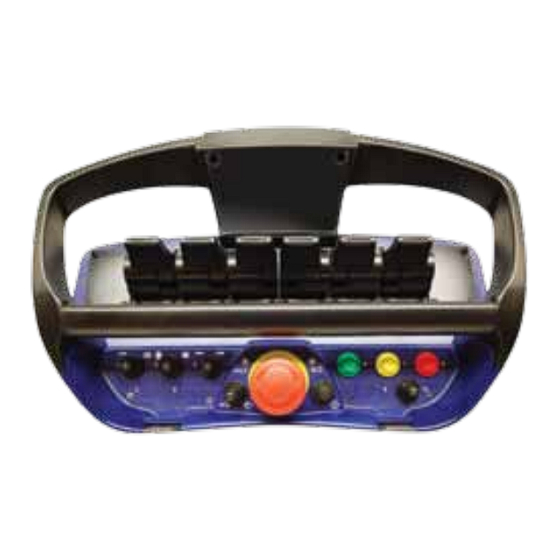
Portable Control Unit Definition
Identifies and explains the components of the Portable Control Unit (PCU).
Central Unit G2B Definition
Identifies and explains the components of the Central Unit G2B.
Central Unit G3B Definition
Identifies and explains the components of the Central Unit G3B.
Cable or Radio Communication
Explains the priority of cable communication over radio communication.
Cable Connection Schematics
Details pin assignments for PCU and Central Unit cable connections.
Inputs & Outputs
Analogue Functions
Shows standard analogue input assignments for MAXI and MINI PCU platforms.
Portable Control Unit MAXI Digital Inputs
Details digital input assignments for the PCU MAXI platform.
Portable Control Unit MINI Digital Inputs
Details digital input assignments for the PCU MINI platform.
Digital Functions
Explains digital function assignments for PCU MINI and MAXI platforms.
Terminal Schematics for Current Controlled Central Unit G2B
Shows terminal pin assignments for current controlled Central Unit G2B.
Terminal Schematics for Voltage Controlled Central Unit G2B
Shows terminal pin assignments for voltage controlled Central Unit G2B.
Terminal Schematics for Central Unit G2B CAN Interface
Details terminal connections for the CAN interface on Central Unit G2B.
Connection Schematics for Central Unit G3B
Provides pin assignments for Central Unit G3B connectors.
Operational Indications
Central Unit Status and Operational Indications
Explains status LEDs and LED display for Central Unit G2B/G3B.
Central Unit LED-Display
Details various status indications shown on the Central Unit LED-display.
Portable Control Unit Status Indications
Explains status indications from the Micro-LED and Power-LED on the Portable Control Unit.
Error Code Indications
General Description
Describes the fault monitoring and error indication process for the system.
Central Unit Error Codes
Explains how Central Unit error codes are displayed and provides a flowchart of error behavior.
Error Codes
Lists Central Unit error codes, their causes, and recommended actions.
Portable Control Unit Error Codes
Lists error codes indicated by the Power-LED and buzzer on the Portable Control Unit.
Radio
General Description
Describes radio communication as a bus link for data transfer between PCU and CU.
Determining Radio Quality
Explains how to determine radio quality using LEDs and the LED-display.
Diagnostics Mode
General Description
Introduces the diagnostics mode for system diagnosis and management.
Activating Diagnostics Mode
Provides step-by-step instructions for activating the diagnostics mode.
Table / Diagnostics Data
Lists diagnostic data positions and their meanings.
Position 1 - Analogue Output Status
Explains how to view analogue output status and real-time values in diagnostics mode.
Position 2 - Digital Output Status
Details how to check digital output status and current values in diagnostics mode.
Position 3 - Digital Input Status
Details how to check digital input status and current values in diagnostics mode.
Position 4 - Error Code Log
Explains how to view the 5 most recent error codes in diagnostics mode.
Clear Error Code Log
Instructions to clear the Central Unit error code log.
Position 5 - Program Save
Describes how to save current settings in diagnostics mode.
Position 6 - Program Load
Describes how to load previously stored settings in diagnostics mode.
Position 7 - Central Unit Program Version
Shows how to view the Central Unit program version in diagnostics mode.
Position 8 - Portable Control Unit Program Version
Shows how to view the Portable Control Unit program version in diagnostics mode.
Online Programming Mode
General Description
Introduces online programming for system adaptation and calibration from the PCU.
Activating Online Programming Mode
Provides step-by-step instructions for activating online programming mode.
Table / Programming Options
Lists programming options available in online mode, their indications, and meanings.
Position 01 - Direction
Details adjustment of lever movement direction in programming mode.
Position 02 - Start Speed SET1
Explains adjustment of start speed for SET1 in programming mode.
Position 03 - Stop Speed SET1
Explains adjustment of stop speed for SET1 in programming mode.
Position 04 - Micro Speed SET1
Details adjustment of micro speed for SET1 in programming mode.
Position 05 - Start Ramp SET1
Explains adjustment of start ramp for SET1 in programming mode.
Position 06 - Stop Ramp SET1
Explains adjustment of stop ramp for SET1 in programming mode.
Position 07 - Start Speed SET2
Details adjustment of start speed for SET2 in programming mode.
Position 08 - Stop Speed SET2
Explains adjustment of stop speed for SET2 in programming mode.
Position 09 - Micro Speed SET2
Details adjustment of micro speed for SET2 in programming mode.
Position 10 - Start Ramp SET2
Explains adjustment of start ramp for SET2 in programming mode.
Position 11 - Stop Ramp SET2
Explains adjustment of stop ramp for SET2 in programming mode.
Position 12 - Start Speed SET3
Details adjustment of start speed for SET3 in programming mode.
Position 13 - Stop Speed SET3
Explains adjustment of stop speed for SET3 in programming mode.
Position 14 - Micro Speed SET3
Details adjustment of micro speed for SET3 in programming mode.
Position 15 - Dump Valve Delay Time
Explains adjustment of dump valve delay time in programming mode.
Portable Control Unit Self Test Mode
General Description
Introduces the internal self-test mode for controlling PCU switches and levers.
Activating Portable Control Unit Self Test Mode
Provides step-by-step instructions for activating the PCU self-test mode.
ID-Code Programming
General Description
Explains the purpose of unique ID-codes for radio communication between PCU and CU.
Procedure
Details the step-by-step procedure for programming the ID-code.
G2B Standard Cable Kits
General Description
Describes various standard cable kits for system configurations and valves/coils.
Standard Supply Cable Kits
Details supply cable kits for power, DV output, digital functions, and CANBUS.
Standard Valve Cable Kits for Sauer-Danfoss PVG-32
Specifies valve cable kits for connecting Sauer-Danfoss PVG-32 module.
Standard Valve Cable Kits for HAWE
Specifies valve cable kits for connecting HAWE module.
Standard Valve Cable Kits for PWM Solenoids
Specifies valve cable kits for connecting PWM solenoids.
Need help?
Do you have a question about the RC400 G3B and is the answer not in the manual?
Questions and answers