Table of Contents
Advertisement
Quick Links
Advertisement
Table of Contents

Related Manuals for BUNNING LoPro 780


Summary of Contents for BUNNING LoPro 780
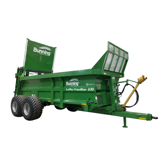
- Page 1 670 - 780 LoPro Manure Spreader Owners Manual...
- Page 3 LOPRO 670 & 780 MANURE SPREADER – INSTRUCTION & SPARES MANUAL Thank you for buying a Bunning spreader. For your Bunning guarantee please fill in the form below and return it to Norwood Sales, Inc. LoPro Warranty Registration Form Customer Name Company Name Address Zip Code Telephone Email Machine ID Number ID No. Exa mpl e 9999/U/MSL180 Date of delivery Dealer Important Data Protection Information. We or our business partners may contract you by mail, telephone, e‐mail or other electronic messaging services with offers of goods and services or information that may be of interest to you. By providing us with your telephone number or e‐mail address you consent to being contacted by these methods. If you do not wish to receive marketing information by these methods from GT Bunning or our business partners please tick this box. Return Address: Norwood Sales 11202 38 St S Horace, ND 58047 ...
- Page 4 LOPRO 670 & 780 MANURE SPREADER – INSTRUCTION & SPARES MANUAL Bunning LoPro Pre‐Delivery Inspection sheet The purpose of this document is to ensure that the operator, hirer or owner is fully appraised of all safey guidelines and operating and maintenance methods before taking possession of the machine. GENERAL LIGHTING Ensure the operator receives a copy of the Check operation of lights instruction & spares manual. Draw attention to the safety decals Check condition of cabling & 7 pin connector. located on the machine. Explain the functions of the machine. Locate, identify & explain spreader to towing vehicle air ,hydraulic and electric connectors. Check oil level of floor drive gearbox and auger drive gearbox. Explain how to cut the PTO guard to size and where to fit the safety chains. BRAKING HYDRAULICS & PNUEMATICS Check hydraulic hose condition especially Check operation of parking brake. brake hoses & connectors. Check hydraulic cylinder for leaks and Check operation of service brake. damage. Check air system hose condition and connectors. (Option). STRUCTURE WHEELS & TYRES Check condition of body, drawbar & augers Check condition of tyres.
-
Page 5: Table Of Contents
LOPRO 670 & 780 MANURE SPREADER – INSTRUCTION & SPARES MANUAL CHASSIS SERIAL NUMBER ................PAGE SECTION & CONTENTS Preface 5 How to use this manual 5 Operating on public roads ... - Page 6 LOPRO 670 & 780 MANURE SPREADER – INSTRUCTION & SPARES MANUAL 4. HEALTH AND SAFETY & POTENTIAL HAZARDS 4.1 Hazardous machinery warning. 49 4.2 Loss of control. 49 4.3 Operation around bystanders. 49 4.4 Hydraulic fluid penetration or burning. 49 4.5 Electrocution. ...
-
Page 7: Preface
LOPRO 670 & 780 MANURE SPREADER – INSTRUCTION & SPARES MANUAL PREFACE The instructions in the manual must be read carefully and followed by all persons concerned with the operation, maintenance, repair or inspection of this machine in order to prevent accidents. Read especially sections relating to safety, operating instructions and maintenance. The use of spare parts, accessories and additional equipment which is not originally manufactured checked and release by GT Bunning Ltd can have a negative effect on specific design features of the machine and on its operability. This may impair its operating safety, as well as safety at work for the operator and could invalidate warranty. GT Bunning will in no way be liable for damage or personal injury caused by the use of other than original GT Bunning parts, accessories and additional equipment. Technical specifications, dimensions and weights are given with the usual tolerances (+ or – 2%). GT Bunning Ltd operates a policy of continual improvement; as such some items in this manual may differ slightly from that of your machine. GT Bunning reserves the right to make changes to the machine or manual without notice. If in any doubt regarding any aspect of the design or operation of this machine contact GT Bunning Ltd or your GT Bunning Ltd agent for clarification. HOW TO USE THIS MANUAL The manual contains sections that cover all of the following, Safety, Operating instructions, Maintenance, ... -
Page 8: Introduction
LOPRO 670 & 780 MANURE SPREADER – INSTRUCTION & SPARES MANUAL INTRODUCTION This manual provides information on the use, adjustment and servicing of the GT Bunning range of Lowlander spreader. Following the advice on the correct maintenance and servicing procedures will ensure maximum performance and a long service life of your machine. Failure to carry out maintenance work correctly, or incorrect operation will result in poor machine efficiency and loss of valuable time. By ensuring the correct operation, and by carrying out maintenance and service work with care, you will be able to make full use of the technical knowledge and the experience with which your Lowlander spreader was originally designed. DISPOSAL Upon completion of the useful life of the machine, all parts can be disposed of at a suitable waste disposal facility. Care must be taken if oxy‐acetylene cutting equipment is to be used. The wheels and tires, hydraulic cylinders, valves and hoses must be removed before using cutting equipment. Oil must be drained collected and disposed of in accordance with current legislation. Electrical components must be disposed of in accordance with the relevant legislation. Page 6... -
Page 9: Ec Declaration Of Conformity
LOPRO 670 & 780 MANURE SPREADER – INSTRUCTION & SPARES MANUAL G.T.BUNNING & SONS LIMITED SPREADERS, TRAILERS & TANKS Telephone: 01362 860352 Registered Office: Fax: 01362 860930 Smithy House, TheGreen E‐mail: sales@gtbunning.co.uk Gressenhall, Dereham Norfolk, NR20 4DT www.gtbunning.co.uk EC MACHINERY DIRECTIVE 2006/42/EC DECLARATION OF CONFORMITY We hereby ceritify that the machinery stipulated below complies with all the relevant provisions of the EC ... -
Page 10: Machine Over View
LOPRO 670 & 780 MANURE SPREADER – INSTRUCTION & SPARES MANUAL MACHINE OVER VIEW DESCRIPTION BODY DRAWBAR STONE GUARD FRONT PILLAR PTO DRIVE LINE FINGER GUARD SUPPORT LEG LADDER WHEEL & TYRE ASSEMBLY AUGER GEARBOX FLOOR DRIVE GEARBOX, MOTOR AND VALVE AUGER LAMP ASSEMBLY AXLE Page 8 ... -
Page 11: Operating Instructions
LOPRO 670 & 780 MANURE SPREADER – INSTRUCTION & SPARES MANUAL 1. OPERATING INSTRUCTIONS The intended purpose of the vehicle is to tow and spread manure and other materials. 1.1 Hitching to tractor. Attach spreader to pick‐up hook or static hitch stub. Do not attach to swinging drawbar or pick‐up hook in extended position. Remove screwjack from drawbar (if fitted) and locate in transport position provided at the front of spreader. Turn off the tractor and remove key before fitting PTO. Slide the tractor end of the PTO shaft out and fit to the tractor PTO. Lay the two halves of the PTO shaft alongside one another and mark the required lengths, allowing for turning. Maximum pull out of 12 inches of the 2 shafts. Cut to size and clean burrs at each end of shaft KEEP SHAFT SLIDING SURFACES GREASED. Attach chains fitted to PTO guard (to prevent rotation of guard) to suitable point on the tractor and hole provided on metal cover over PTO shaft on spreader. Ensure that the spring loaded pins in splined yokes are fully locked in position. Always disengage the PTO when turning sharply to avoid damage to shafts universal joints. Where a wide angle PTO is fitted attach this end to the tractor. Please refer to the DVD for more information. ... -
Page 12: Coupling Of Hydraulic Hoses
LOPRO 670 & 780 MANURE SPREADER – INSTRUCTION & SPARES MANUAL 1.2 Coupling of hydraulic hoses. Fit the two hoses for the floor drive hydraulic motor (one to feed and one for return) to double spool valve on tractor. Choose position of spool lever for ease of control to obtain floor movement to rear. Reversing of floor is done by selecting the opposite position of the hydraulic control lever. Universal quick release probes are fitted as standard to hose ends. Mark hose as required to assist in the future coupling for correct position of feed and return. When a slurry door is fitted connect the hydraulic hoses to a double spool valve and select the hose positions to suit the operator to open and close the door. Fit hydrualic brake hose to trailer brake valve on tractor (male fitting). A universal female brake coupling is fitted as standard to the hose ends. N.B CHECK DIRECTION OF FLOOR BEFORE LOADING. Do not run floor in reverse with full load. Speed of floor in reverse is at MAXIMUM. Only reverse floor for a few seconds. Ensure the braking system is connected and that it functions correctly before moving. FLOOR RETURN SLURRY DOOR CLOSE FLOOR PRESSURE SLURRY DOOR OPEN Page 10 ... -
Page 13: Floor Adjustment
LOPRO 670 & 780 MANURE SPREADER – INSTRUCTION & SPARES MANUAL 1.3 Floor adjustment. When adjusting floor chains ensure that the adjustment is carried out equally to both sides. DO NOT ALLOW THE CHAINS TO BECOME TOO LOOSE. ADJUST CHAINS AFTER A FEW LOADS. KEEP CHAINS ADJUSTED CORRECTLY AT ALL TIMES, A GUIDE IS TO BE ABLE TO SEE A WHOLE LINK BELOW FRONT BOTTOM EDGE OF SPREADER i.e. FROM CENTRE TO FRONT. Reverse floor The floor should only be reversed for very short periods, to clear the augers. Do not reverse if the floor chain is slack, tighten floor chain first. 1.4 Method of operation. 1) Select speed of floor required on control valve. 2) Engage PTO to power the rear augers – tractor engine revs low. 3) Raise slurry door fitted. 4) Engage spool valve to power floor to rear. 1.5 Slurry Door As the load height reduces lower the slurry door to cover the augers. This will help prevent foreign objects being thrown forward. Page 11 ... -
Page 14: Maintenance
LOPRO 670 & 780 MANURE SPREADER – INSTRUCTION & SPARES MANUAL 2. MAINTENANCE 2.1 Lubrication of spreader. DAILY GREASE Front and rear floor shaft Overrun clutch to front of main ‘T’ gearbox Hitch eye WEEKLY GREASE All sealed bearing – 1/2 pump of grease gun maximum. TAKE CARE NOT TO DAMAGE GREASE SEAL BY OVERGREASING Sliding tube of PTO shaft. PTO universal joints – Follow manufacturer’s instructions. Screwjack top (when fitted) Shearbolt bush MONTHLY Check gearbox oil levels ANNUALLY Change oil to all gearboxes TYPE OF LUBRICATION GREASE Multi purpose ... - Page 15 LOPRO 670 & 780 MANURE SPREADER – INSTRUCTION & SPARES MANUAL b. Rear Shaft. • Grease both left and right bearings. 3. Grease the Overrun Clutch to front of the auger gearbox. WEEKLY (40 HRS) 1. Check wheel nuts. Re‐torque as needed. 2. Grease all sealed bearings a. Driveline hanger bearings (2 or 3 depending on model). b. Top auger bearings (Grease nipples access provided on right turret). 3. Grease the telescoping section of the PTO shaft. Page 13 ...
- Page 16 LOPRO 670 & 780 MANURE SPREADER – INSTRUCTION & SPARES MANUAL 4. Grease PTO input drive system. a. Input shaft. b. Cross joint fittings. c. Guard bearings. d. Shear bolt housing. e. Over‐running clutch (5 pumps). 5. Grease the implement jack top. 6. Check gearbox oil level a. Floor Chain Drive Gearbox Oil should be level with the middle of the sight glass. Add oil as required through the top plug. b. Auger Gearbox Spreader must be unhooked from tractor and set on level ground to check oil. Oil should be level with the middle of the sight glass. ...
-
Page 17: Amount Of Oil Required To Fill Gearboxes
LOPRO 670 & 780 MANURE SPREADER – INSTRUCTION & SPARES MANUAL Grease brake pivot bushings (Tandem Suspension machines). Grease parking brake leaver joint. Check and adjust the apron chain tension. ANNUALLY 1. Change oil to all gearboxes. 2. Check the condition of the frame sealing flaps. Replace if not sealing the sides or bottom. a. Front. b. Rear Slurry Door Auger Deck. 3. Check brake setting. Brakes can be checked by depressing the brake petal with the engine running and the tractor in gear; release clutch to determine brake adjustment. 4. Check condition of rotor blades and paddles. Repair when there are loose bolts, cracked welds, chipped, bent or broken blades or paddles. Replace when any components are worn within 1 inch of flighting. 5. Clean machine. 6. Check general hardware/bolt tightness. Retighten if necessary. It is recommended to apply waste oil to the floor chains periodically when spreading dry material and particularly at ... -
Page 18: Service Record
LOPRO 670 & 780 MANURE SPREADER – INSTRUCTION & SPARES MANUAL 2.4 SERVICE RECORD See Lubrication and Mainteneance sections for details of service. Copy this page to continue record. ACTION CODE CK = CHECK CL = CLEAN G = GREASE Page 16 ... -
Page 19: Shearbolt Protection
LOPRO 670 & 780 MANURE SPREADER – INSTRUCTION & SPARES MANUAL 2.5 Shearbolt Protection. Only one shearbolt is fitted to the spreader. This is located on the spreader end of the PTO shaft. The bolt is M10 x 60 grade 6.8 mild steel. ON NO ACCOUNT MUST A BOLT OF HIGHER GRADE THAN 6.8 TENSILE STRENGTH BE FITTED. 2.6 Greasing points GREASE POINT ALL BEARINGS IN DRIVE LINE FRONT SHAFT PTO KNUCKLES REAR SHAFT BEARINGS TOP OF AUGERS WALKING BEAM PIVOT PINS DRAWBAR REAR PIN Page 17 ... -
Page 20: Tire & Wheel
LOPRO 670 & 780 MANURE SPREADER – INSTRUCTION & SPARES MANUAL 2.7 Tire & Wheel Maintenance of correct inflation pressure (46PSI) is the basic essential factor in obtaining the best performance and life from a pneumatic tire. The air inside the tire enables it to carry a load. It is only when the inflation pressure is correctly matched that the tire adopts its optimum cross‐sectional shape and the tread rests correctly on the road surface with the correct pressure distribution across its whole width, thus allowing the sidewalls to provide the required degree of flexibility. Both performance and life of the tires will suffer if pressures are unsuitable so both over or under inflation ( or overload which has the same effect ) are similary undesirable. Underinflation results in excessive deflection which increases the heat generated by the tire, this in turn leads to its eventual disintigration. In addition the distortion of the casing will result in the lifting of the centre of the tread, thus overloading the outer edges of the tread, producing rapid wear at those points. Overinflation distorts the tire’s casing, but in this case it tends to lift the outer edges of the tread off the road surface and imposes extra load and more rapid wear on the centre of the tread. Owing to reduced flexibilty the tire will be more vulnerable to impact damage, ride quality will be impaired and the wheels will be more liable to bounce which can result in skidding due to brakes locking. Unlike cars on which tire loads do not vary greatly it is not practicable to provide standard recommendations. This is because tire loading and operating conditions vary widely. ... -
Page 21: Pto Inspection
LOPRO 670 & 780 MANURE SPREADER – INSTRUCTION & SPARES MANUAL 2.8 PTO Inspection PROBLEM PROBABLE CAUSE POSSIBLE SOLUTION Page 19 ... - Page 22 LOPRO 670 & 780 MANURE SPREADER – INSTRUCTION & SPARES MANUAL 5.3 PROBLEMS AND POSSIBLE SOLUTIONS PROBLEM PROBABLE CAUSE POSSIBLE SOLUTION Page 20 ...
-
Page 23: Drawings & Parts Lists
LOPRO 670 & 780 MANURE SPREADER – INSTRUCTION & SPARES MANUAL 3. DRAWINGS & PARTS LISTS 3.1 FLOOR DRIVES Page 21 ... - Page 24 LOPRO 670 & 780 MANURE SPREADER – INSTRUCTION & SPARES MANUAL FLOOR SPEED CONTROL UNITS: 90‐36‐0003: 16GPM Manual (Single Floor Drive) 90‐36‐0062: 30GPM Manual (Dual Floor Drive) 90‐36‐0049: 20GPM Electric (Single Floor Drive) 90‐36‐0047: 30GPM Electric (Dual Floor Drive) Page 22 ...
- Page 25 LOPRO 670 & 780 MANURE SPREADER – INSTRUCTION & SPARES MANUAL FLOOR DRIVE RELIEF VALVES This valve is cross line type and fitted to the hydraulic motor on the floor drive gearbox. The pressure can be varied to suit the material being spread. To adjust, engage the oil flow via the spool valve on the tractor, insert the Allen key to prevent the screw from rotating whilst slacking off the lock nut. Use the Allen key, turn the screw clockwise to increase pressure until the floor starts to move. Use the Allen key to ...
- Page 26 LOPRO 670 & 780 MANURE SPREADER – INSTRUCTION & SPARES MANUAL FLOOR DRIVE GEARBOX B3122 Page 24 ...
- Page 27 LOPRO 670 & 780 MANURE SPREADER – INSTRUCTION & SPARES MANUAL REAR SHAFT ASSEMBLY Page 25 ...
- Page 28 LOPRO 670 & 780 MANURE SPREADER – INSTRUCTION & SPARES MANUAL REAR SHAFT ASSEMBLY PARTS LIST PART No. DESCRIPTION NGTB0569 REAR SHAFT NAMS0268 GYPSY WHEEL 90‐17‐2002 KEY 18x11x80 90‐17‐2003 KEY 18x11x190 90‐33‐0008 GEARBOX NDMS0574 TORQUE PLATE 90‐35‐0010 HYDRAULIC MOTOR 250CL NAMS0204‐LW LH BEARING FLANGE NAMS0204‐RW RH BEARING FLANGE 90‐24‐4017 ACM BUSH M60 90‐10‐9520 M16 x 40mm BOLT NDMS0624 SPACER 90‐14‐9009 M16 SPRING WASHER 90‐10‐1597 BOLT NDMS0582 END PLATE NBUN0025 SPACER 90‐10‐1605 BOLT 90‐13‐2593...
-
Page 29: Front Shaft & Chains
LOPRO 670 & 780 MANURE SPREADER – INSTRUCTION & SPARES MANUAL 3.2 FRONT SHAFT AND CHAIN ASSEMBLY PART No. DESCRIPTION N315TUBE‐2 FLOOR SLAT BOX TYPE NGTB0323 ADJUSTER M30 90‐19‐4004 JOINER LINK ASSEMBLY NAMS0042 CLEANER FRONT GYPSY 90‐10‐0393 BOLT M8 x 12 90‐24‐4017 ACM BUSH M60 NAMS0635 BEARING BLOCK NBUN0025 SPACER NAMS2312 CHAIN TABBED 3RD LINK LH NAMS2313 CHAIN TABBED 3RD LINK RH NDMS0616 FRONT SHAFT NDMS0678 PLATE WHEELS WELD ON 90‐23‐0002 GREASE NIPPLE 90‐19‐4003 DOG BONE 20mm CHAINS Page 27 ... -
Page 30: Augers & Gearboxes
LOPRO 670 & 780 MANURE SPREADER – INSTRUCTION & SPARES MANUAL 3.3 AUGERS & GEARBOXES QTY PART No. DESCRIPTION NAMS3684 AUGER LH SRT 18 NBUN1041 AUGER LH SRT 20 NAMS3685 AUGER RH SRT 18 NBUN1042 AUGER RH SRT 20 NAMS0249 DRIVE FLANGE SRT 18 NAMS3340 DRIVE FLANGE SRT 20 90‐48‐2002 RUBBER DRIVE BLOCK SRT 18 NBUN0204 RUBBER DRIVE BLOCK SRT 20 NDMS2985 AUGER BLADE 90‐10‐9560 BOLT, M14 CLIPPED PLOW 90‐13‐9020 NUT, M14 CENTER LOCK NDMS2472 CUTTER POINT HD BORON 90‐10‐9651 BOLT, M14 X 50 NBUN0033 SPACER 90‐24‐0045... - Page 31 LOPRO 670 & 780 MANURE SPREADER – INSTRUCTION & SPARES MANUAL GEARBOX SRT18‐1000/420 – 90‐33‐0009 (B3182) *Standard Equipment Page 29 ...
- Page 32 LOPRO 670 & 780 MANURE SPREADER – INSTRUCTION & SPARES MANUAL GEARBOX SRT18‐1000/420 THRU – 90‐33‐0012 (B3186) [Option – Spinner Deck Ready] Page 30 ...
- Page 33 LOPRO 670 & 780 MANURE SPREADER – INSTRUCTION & SPARES MANUAL GEARBOX SRT20‐1000/420 THRU – 90‐33‐0026 (B3196) [Option – SRT20 Upgrade] Page 31 ...
- Page 34 LOPRO 670 & 780 MANURE SPREADER – INSTRUCTION & SPARES MANUAL GEARBOX SRT18‐1000/520 – 90‐33‐0027 (B3190) [For Detachable Spinner Deck] Page 32 ...
-
Page 35: Pto Shafts
LOPRO 670 & 780 MANURE SPREADER – INSTRUCTION & SPARES MANUAL 3.4 PTO AND TRANSMISSION TRANSMISSION MODEL 670 & 780 670 T60 Driveline (Standard) 780 T60 Driveline (Standard) PART No. DESCRIPTION QTY PART No. DESCRIPTION 90‐32‐4001 PTO SHAFT F/M 90‐32‐4001 PTO SHAFT F/M 90‐32‐4006 PTO SHAFT M/M 90‐32‐4002 PTO SHAFT M/M 90‐32‐4007 PTO SHAFT F/M 90‐32‐4007 PTO SHAFT F/M 90‐32‐4003 PTO SHAFT F/F 90‐32‐4003 PTO SHAFT F/F 90‐24‐0035 BEARING M35 90‐24‐0035 BEARING M35 NAMS1524 GUARD NAMS1524 GUARD 90‐33‐0009 GEARBOX 90‐33‐0009 GEARBOX ... - Page 36 LOPRO 670 & 780 MANURE SPREADER – INSTRUCTION & SPARES MANUAL WALTERSCHIED WIDE ANGLE PTO – SHEAR BOLT PROTECTION 21 Spline for T60 Driveline – 90‐32‐4005 (43005) 20 Spline for T60 Driveline – 90‐32‐4009 (43007) [Standard Equipment] 20 Spline for T80 Driveline – 90‐32‐4028 (43004/1) WALTERSCHEID WIDE ANGLE PTO – CAM CLUTCH PROTECTION 21 Spline for T60 Driveline – 90‐32‐4015 (43005TL) 20 Spline for T60 Driveline – 90‐32‐4022 (43007TL) 20 Spline for T80 Driveline – 90‐32‐4016 (43008TL) Page 34 ...
- Page 37 LOPRO 670 & 780 MANURE SPREADER – INSTRUCTION & SPARES MANUAL COMER T60 UNDERBODY DRIVESHAFT DESCRIPTION PART No. SPLINED BAR 42041 T60 INNER TUBE (PER METER) 42775 T60 OUTER TUBE(PER METER) 42770 YOKE TO OUTER 42745 ROLL PIN 42030 JOURNAL 42701 YOKE 6 SPLINE CLAMP BOLT 42715 42766 YOKE 6 SPLINE OVERRUN CLAMPBOLT 1¾ 42760 1⅜ 6 SPLINE YOKE QUICK RELEASE SHEARBOLT 42705 1⅜ 6 SPLINE YOKE QUICK RELEASE SHEARBOLT 42725 21 SPLINE YOKE QUICK RELEASE SHEARBOLT 1 ⅜...
- Page 38 LOPRO 670 & 780 MANURE SPREADER – INSTRUCTION & SPARES MANUAL WALTERSCHEID P.T.O SHAFT PART No. DESCRIPTION 43312 YOKE TO 6 SPLINE 43313 YOKE TO 21 SPLINE 43325 JOURNAL 43314 YOKE TO S4 TUBE 43315 YOKE TO S5 TUBE 43317 YOKE TO SHEAR BOLT CLUTCH B1310 SHEAR BOLT 6.8 HARDNESS 43301 S4 TUBE INNER 43302 S5 TUBE OUTER 43441 GUARD COMPLETE 43443 GAURD INNER 43444 GUARD OUTER 42030 ROLL PIN 42030 ROLL PIN ...
- Page 39 LOPRO 670 & 780 MANURE SPREADER – INSTRUCTION & SPARES MANUAL WALTERSCHEID WIDE ANGLE P.T.O SHAFT PART No. 43102 PART No. DESCRIPTION 43005 W/A P.T.O SHAFT COMPLETE 21 SPLINE 43006 W/A P.T.O SHAFT COMPLETE 6 SPLINE 43007 W/A P.T.O SHAFT COMPLETE 20 SPLINE 43390 21 SPLINE INNER W/A HALF SHAFT WITH OUTER GUARD 43391 6 SPLINE INNER W/A HALF SHAFT WITH OUTER GUARD 43389 20 SPLINE INNER W/A HALF SHAFT WITH OUTER GUARD 43392 6 SPLINE INNER W/A HALF SHAFT WITH OUTER GUARD 43472 W/A HALF GUARD OUTER 43470 W/A HALF GUARD INNER 43360 W/A YOKE TO 21 SPLINE 43361 W/A YOKE TO 6 SPLINE 43362 W/A YOKE TO 20 SPLINE 43322 AS ‐ LOCK SIZE C (AG118) 43374 SHEAR BOLTS CLUTCH TO YOKE B1310 SHEAR BOLT 6.8 HARDNESS 43367 W/A JOURNAL KIT COMPLETE 43365 W/A CENTRE BODY 43366...
-
Page 40: Slurry Door
LOPRO 670 & 780 MANURE SPREADER – INSTRUCTION & SPARES MANUAL 3.5 GUILLOTINE SLURRY DOOR PART No. DESCRIPTION NGTB1100 GUILLOTINE DOOR 90‐39‐0036 HYDRAULIC RAM 90‐16‐3360 TOP RAM PIN DIA 5/8" 90‐16‐3401 BOTTOM RAM PIN DIA 3/4" NGTB0205 RUBBER SKIRT W.B NGTB0206‐2 CLAMP STRIP 90‐16‐0160 SPLIT PIN Page 38 ... - Page 41 LOPRO 670 & 780 MANURE SPREADER – INSTRUCTION & SPARES MANUAL GUILLOTINE SLURRY DOOR HYDRAULIC CIRCUIT. PART No. DESCRIPTION 90‐38‐0118 Male Quck Coupler, 8FP 90‐38‐0022 DUMMY 1/2" FEMALE 90‐38‐0180 3/8"‐3/8"‐ BPT BULKHEAD 90‐37‐1182 Hose, 06 x 100, 08MP x 06FJX 90‐37‐1194 Hose, 06 x 360, 06FJX x 06FJX90 90‐37‐1195 Hose, 06 x 360, 06FJX90 x 06FJX90 Page 39 ...
-
Page 42: Drawbar
LOPRO 670 & 780 MANURE SPREADER – INSTRUCTION & SPARES MANUAL 3.6 DRAWBAR ... -
Page 43: Axle Assembly
LOPRO 670 & 780 MANURE SPREADER – INSTRUCTION & SPARES MANUAL 3.7 AXLE ASSEMBLY Page 41 ... - Page 44 LOPRO 670 & 780 MANURE SPREADER – INSTRUCTION & SPARES MANUAL Page 42 ...
- Page 45 LOPRO 670 & 780 MANURE SPREADER – INSTRUCTION & SPARES MANUAL Page 43 ...
-
Page 46: Lamp Covers
LOPRO 670 & 780 MANURE SPREADER – INSTRUCTION & SPARES MANUAL 3.8 LAMP COVERS [NGTB1079‐1 WELDMENT, LAMP COVER RS] Page 44 ... - Page 47 LOPRO 670 & 780 MANURE SPREADER – INSTRUCTION & SPARES MANUAL 3.9 DETACHABLE SPINNER DECK (Optional Equipment) Page 45 ...
-
Page 48: Detachable Spinner Deck
LOPRO 670 & 780 MANURE SPREADER – INSTRUCTION & SPARES MANUAL 9.6 DETACHABLE SPINNER DECK PART No. PART No. DESCRIPTION NGTB1153 CANOPY FRAME NGTB1229 CANOPY GATE NGTB1158 BLADE MOUNT RH NGTB1156 BLADE MOUNT LH NBUN1036 SPINNER DISK RH NBUN1035 SPINNER DISK LH NGTB0565 SPINNER BLADE NGTB1160 SHORT OUTER COUPLER NGTB1160‐2 LONG OUTER COUPLER NAMS0758 INNER COUPLER 90‐48‐2004 RUBBER DRIVE BLOCK NBUN1037 GATE ADJUST HANDLE NGTB0419 SHORT SKIRT CLAMP PLATE NGTB0559 LONG SKIRT CLAMP PLATE NGTB0126 DECK HANGER HOOK 90‐22‐0031 HINGED FASTENER 90‐33‐0027 BERMA SRT 18/1830 1000‐520 3IN1 NGTB0558... -
Page 49: Body Seals
LOPRO 670 & 780 MANURE SPREADER – INSTRUCTION & SPARES MANUAL 3.10 BODY SEAL RUBBERS PART No. DESCRIPTION NGTB0205 SLURRY DOOR RUBBER NGTB0205 FRONTWALL RUBBER NGTB0201 DOUBLE WIPER RUBBER STRIP NGTB0250 DECK RUBBER 3.11 WEIGH CELL SPARES (Optional Equipment) Load cell 11’ lead 90‐46‐2052 Load cell 40’ lead 90‐46‐2051 Page 47 ... -
Page 50: 3.12 Lighting
LOPRO 670 & 780 MANURE SPREADER – INSTRUCTION & SPARES MANUAL 3.12 LIGHTING WIRING FOR 12v 7 PIN PLUG 1) WHITE (EARTH) – R – STOP 2) BLACK – G – R.H. INDICATOR 3) YELLOW – BR – TAIL 4) RED – W – EARTH 5) GREEN – BL – SIDEMARKERS 6) BROWN – Y – L.H. INDICATOR 7) BLUE – B – FOG Page 48 ... -
Page 51: Hazardous Machinery Warning
LOPRO 670 & 780 MANURE SPREADER – INSTRUCTION & SPARES MANUAL 4. HEALTH AND SAFETY 4.1 Hazardous machinery warning This machine is hazardous if improperly used and may cause serious injury or death if not used in accordance with these operating instructions and safety warnings. Employers are required to train and supervise all operators and assistants to observe safety precautions described by this handbook, the installation process and by warning decals. ... -
Page 52: Machinery Start Up
LOPRO 670 & 780 MANURE SPREADER – INSTRUCTION & SPARES MANUAL 4.8 Machinery start up Sound the horn before starting this machine. 4.9 Machinery shut down This machine must be operated from a tractor driver’s seat. The tractor and machine must be shut down, the key removed and hydraulics lowered, before the driver leaves the seat or any adjustments or repairs are made. 4.10 Additional driver protection Extra protection can be achieved by lowing the slurry door as the load decreases in height. 4.11 PTO Connection and gaurding Improper PTO connection and operation may cause machine failure and injury to an operator. PTO shaft guards must be used at all time. ALWAYS VERIFY PTO GUARD CHAIN IS PROPERLY INSTALLED. 4.12 Personal protective equipment (PPE) When maintaining and operating this machine make sure appropriate PPE is worn. i.e. Overalls, gloves, safety shoes, eye and ear protection. 4.13 Safety decal location i) Warning – When spreading , lower slurry door to cover exposed augers. Page 50 ... -
Page 53: 4.14 Operating Hazard Area
LOPRO 670 & 780 MANURE SPREADER – INSTRUCTION & SPARES MANUAL ii) Danger – Keep hands clear of taildoor and mechanism during operation. 4.14 Operating hazard area Objects can be thrown out from the rotors with sufficient force to severely injure people. Stay away from machine when it is running. Keep others away. Stay out of shaded hazard area. Always know where all additional personnel are located when operating the spreader. Never allow anyone within the hazard area. Stay away from the sides and rear of the spreader when it is running to prevent being hit by flying debris. Rotors can expel solid objects with sufficient force to cause severe injury. Stay out of hazard area. NOTE: Remember any foreign objects hidden in the material i.e. stones, bricks, wood etc. can be thrown further than the actual material, which could result in serious injury or loss of life. Page 51 ... -
Page 54: 4.15 Warnings
During the 3 year warranty period any failures which occur due to faulty components or workmanship must be reported to G.T. Bunning & Sons Ltd before any repairs or replacements of components is carried out. The warranty period commences on the despatch date from the factory. All parts not guaranteed by G.T. Bunning & Sons Ltd are covered by the component manufacturer and are subject to their own warranty. The warranty terms only apply to machines that have been subject to fair wear and tear operation and where routine maintenance has been carried out. ... -
Page 55: Important Information
LOPRO 670 & 780 MANURE SPREADER – INSTRUCTION & SPARES MANUAL 6. IMPORTANT INFORMATION When using the speader in conjunction with a tractor which has a fast and slow response control on the spool valves, check that the control on the spool valve is not in the slow position in respect of the floor drives, as this will over ride the variable floor speed. The spreader always runs very quietly when working, if loud banging noises are heard this will mean that foreign objects are in the material. Obviously the shearbolt may well break. If the shearbolts on the PTO has not sheared and the noises persists STOP THE SPREADER SWITCH OFF TRACTOR ENGINE and check the spreader. From new, it is strongly recommended that you do not use a high pressure cold washer and definatley not a hot pressure washer to the outside of the spreader for 12 weeks. This will damage the paintwork whilst normal curing of the paint takes place. Careful low pressure washing is acceptable. Do not let manure dry and set on fresh paint for the first 3‐4 weeks. During this period it is advisable to clean the machine after use as instructed. Page 53 ... -
Page 56: Notes
LOPRO 670 & 780 MANURE SPREADER – INSTRUCTION & SPARES MANUAL 7. NOTES Page 54 ... -
Page 57: Identification Plate
LOPRO 670 & 780 MANURE SPREADER – INSTRUCTION & SPARES MANUAL 8. IDENTIFICATION PLATE The machine number (VIN) is required with all orders for spare parts and technical enquires. This is necessary in order to ensure correct delivery of spare parts. The identification plate with the machine number is attached to the middle right side of the machine drawbar. 9999/U/MSL 670 Page 55 ... -
Page 58: Technical Data & Specifications
LOPRO 670 & 780 MANURE SPREADER – INSTRUCTION & SPARES MANUAL 9. TECHNICAL DATA & SPECIFICATIONS MODEL GROSS DESIGN (lb) 61,247 68,340 EYE (lb) 12,250 12,250 TARE WEIGHT (lb) 17,247 18,210 PAYLOAD (lb) 44,000 44,000 PAYLOAD + TARE (lb) 61,247 62,210 Bunning tolerance +/‐ 2% MODEL Axle Tandem Tandem Carrying Capcacity 44,000 lbs 44,000 lbs Cubic Feet Level Cubic Feet Heaped Body size (int.inches) 235x72x47 271x72x47 Floor drive Hydraulic Floor speed control Hydraulic variable speed c/w reverse Floor chain size 3/4"... -
Page 59: Machine Dimensions
10. MACHINE DIMENSIONS MODEL 235.2'' 72.0'' 47.0'' 87.0'' 341.3'' 137.5'' 112.9'' 271.2'' 72.0'' 47.0'' 87.0'' 377.3'' 137.5'' 112.9'' Bunning tolerance +/‐ 2% FOR PROMPT SUPPLY OF SPARES, ALWAYS QUOTE THE CHASSIS SERIAL NUMBER, (FOUND ON THE CHASSIS IDENTIFICATION PLATE) This manual should stay with the machine/operator at all times. This manual is an original English language copy. Page 57 ... - Page 60 Alpha Equipment Ltd Local/Intl: 306-731-2954 sales@alphaequipmentltd.com Fax: 306-731-2955 P.O. Box 265 Craven, SK S0G 0W0...
Need help?
Do you have a question about the LoPro 780 and is the answer not in the manual?
Questions and answers