
Related Manuals for AirSep AS-D+


Summarization of Contents
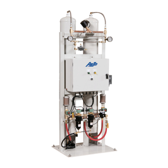
AS-D+ – AS-P
Instruction Manual
Provides instructions for installation, operation, and maintenance of AirSep PSA Oxygen Generator.
Alpha Series
Identifies the product series as Alpha Series.
1.0 Introduction
1.1 General
Overview of the instruction manual's scope and purpose.
1.2 Warnings, Cautions, and Notes
Explains the meaning of safety messages used throughout the manual.
1.3 References to Controls and Indicators
Describes how controls and indicators are identified within the manual.
6.0 Maintenance
6.1 Daily Monitoring
Procedures for daily checks to ensure proper operation.
6.2 Monthly Monitoring
Procedures for monthly inspection and testing of components.
6.3 Depressurizing the Filters
Steps to safely depressurize filter assemblies before maintenance.
6.4 Changing Filter Elements
Instructions for replacing particulate and coalescing filter elements.
6.5 Depressurizing the Oxygen Generator
Procedure to safely depressurize all oxygen generator components.
6.6 Adjusting the Feed Air Regulator
Guidance on how to adjust the feed air regulator settings.
7.0 Troubleshooting
7.1 Technical Support
Contact information for assistance and replacement parts.
7.2 Troubleshooting Chart
A guide to identify and resolve common problems with the oxygen generator.
A. Appendix Technical Data
A.1 Specifications
Technical data and specifications for various oxygen generator models.
A.2 Drawings and Schematics
Illustrations and schematics of the oxygen generator components.
A.3 Electrical Schematics
Electrical diagrams for the oxygen generator models.
B. Appendix Warranty/Returns
B.1 Product Warranty
Details of the warranty coverage for the PSA oxygen generator.
B.2 Limits of Liability
Information regarding limitations of liability for the manufacturer.
B.3 Returning the Oxygen Generator or Component for Service
Procedure for returning units or parts for service or credit.
C. Appendix Component Literature
C.1 Programmable Logic Controller
Literature for the Programmable Logic Controller (Schneider Modicon M221).
C.2 Touchscreen
Literature for the Touchscreen display (Schneider Electric Magelis HMISTU855).
C.3 Filters
Literature for the filters used in the system (Wilkerson Corporation).
C.4 Regulators
Literature for the regulators used in the system (Wilkerson Corporation).
C.5 Valves
Literature for valves used in the system (Neles-Jamesbury, ASCO).
A.1 Magnalube-G
Material Safety Data Sheet for Magnalube-G grease.
D. Appendix
D.1 Oxygen Generator Decommissioning and Disposal Guideline
Guideline for the effective decommissioning and disposal of the oxygen generator.
2.0 Safety
2.1 General
General information about oxygen properties and safety.
2.2 Potential Hazards
Identifies potential risks associated with oxygen and the generator.
3.0 System Description
3.1 General
Overview of the PSA oxygen generation process and unit operation.
4.0 Components Description
4.1 External Components
Illustrates and describes the visible external parts of the generator.
4.2 Adsorbers
Describes the function of the adsorber vessels containing molecular sieve.
4.3 Connections
Details the air inlet, oxygen outlet, and condensate drain connections.
4.4 Manifold Components
Illustrates and describes the manifold components of the generator.
4.5 Control Panel: External Components
Describes the external components of the control panel, including the touchscreen.
4.6 Control Panel: Internal Components
Programmable Logic Controller
Describes the function of the PLC in generator operation.
Oxygen Concentration Monitoring Board
Explains the role of the board in monitoring product oxygen concentration.
Human Machine Interface (HMI)
Details the HMI as the interface between the operator and the generator.
5.0 Installation
5.1 Handling and Unpacking
Guidelines for safely handling and unpacking the oxygen generator.
6.0 Maintenance
6.1 Daily Monitoring
Daily checks for automatic drain valve function.
6.2 Monthly Monitoring
Monthly inspection of filters and testing of automatic drain valve.
7.0 Troubleshooting
7.1 Technical Support
Contact information for troubleshooting assistance and parts.
7.2 Troubleshooting Chart
A table outlining problems, probable causes, and solutions.
A. Appendix Technical Data
A.1 Specifications
General specifications for AS-D+ through AS-P models.
Table A.1: AS-D+ Specifications
Detailed specifications for the AS-D+ model.
Table A.2: AS-E Specifications
Detailed specifications for the AS-E model.
Table A.3: AS-G Specifications
Detailed specifications for the AS-G model.
Table A.4: AS-J Specifications
Detailed specifications for the AS-J model.
Table A.5: AS-K Specifications
Detailed specifications for the AS-K model.
Table A.6: AS-L Specifications
Detailed specifications for the AS-L model.
Table A.7: AS-N Specifications
Detailed specifications for the AS-N model.
Table A.8: AS-P Specifications
Detailed specifications for the AS-P model.
Table A.9: Typical System Set points
Typical set points for system parameters like alarms and pressure.
A.2 Drawings and Schematics
Figure A.1: Typical Pressure Profile
Diagram showing typical pressure profiles and valve cycle sequences.
Figure A.2: Typical Installation Arrangement
Diagram illustrating a typical installation setup for the unit.
Figure A.3: General Arrangement Drawing – AS-D+
General arrangement drawing for the AS-D+ model.
Figure A.4: Flow Schematics – AS-D+
Flow schematic diagram for the AS-D+ model.
Figure A.5: General Arrangement Drawing – AS-E
General arrangement drawing for the AS-E model.
Figure A.6: Flow Schematic – AS-E
Flow schematic diagram for the AS-E model.
Figure A.7: General Arrangement Drawing – AS-G
General arrangement drawing for the AS-G model.
Figure A.8: Flow Schematic – AS-G
Flow schematic diagram for the AS-G model.
Figure A.9: General Arrangement Drawing – AS-J
General arrangement drawing for the AS-J model.
Figure A.10: Flow Schematic – AS-J
Flow schematic diagram for the AS-J model.
Figure A.11: General Arrangement Drawing – AS-K
General arrangement drawing for the AS-K model.
Figure A.12: Flow Schematic – AS-K
Flow schematic diagram for the AS-K model.
Figure A.13: General Arrangement Drawing – AS-L
General arrangement drawing for the AS-L model.
Figure A.14: Flow Schematic – AS-L
Flow schematic diagram for the AS-L model.
Figure A.15: General Arrangement Drawing – AS-N
General arrangement drawing for the AS-N model.
Figure A.16: Flow Schematic – AS-N
Flow schematic diagram for the AS-N model.
Figure A.17: General Arrangement Drawing – AS-P
General arrangement drawing for the AS-P model.
Figure A.18: Flow Schematic – AS-P
Flow schematic diagram for the AS-P model.
A.3 Electrical Schematics – AS-D+ – AS-P
Figure A.19: Electrical Schematic – Sheet 1
Electrical schematic diagram for the AS-D+ and AS-P models, sheet 1.
Figure A.20: Electrical Schematic – Sheet 2
Electrical schematic diagram for the AS-D+ and AS-P models, sheet 2.
Figure A.21: Electrical Schematic – Sheet 3
Electrical schematic diagram for the AS-D+ and AS-P models, sheet 3.
Figure A.22: Electrical Schematic – Sheet 4
Electrical schematic diagram for the AS-D+ and AS-P models, sheet 4.
B. Appendix Warranty/Returns
B.1 Product Warranty
Details the warranty terms and conditions for the PSA oxygen generator.
B.2 Limits of Liability
Outlines the manufacturer's limitations of liability.
B.3 Returning the Oxygen Generator or Component for Service
Procedure for returning units or components for service or credit.
C. Appendix Component Literature
C.1 Programmable Logic Controller
Literature for the Programmable Logic Controller (Schneider Modicon M221).
Schneider Modicon M221 Characteristics
Detailed characteristics of the Schneider Modicon M221 controller.
Modicon M221 Electrical Durability
Information on the electrical durability and specifications of the M221 controller.
Modicon M221 Dimensions and Mounting
Dimensional drawings and mounting guidelines for the M221 controller.
Modicon M221 Connections and Schemas
Details on the connections and schematic diagrams for the M221 controller.
Modicon M221 Performance Curves
Performance curves illustrating derating for the M221 controller.
C.2 Touchscreen
Literature for the Touchscreen (Schneider Electric Magelis HMISTU855).
Schneider Electric Magelis HMISTU855 Characteristics
Detailed characteristics of the HMISTU855 touchscreen.
HMISTU855 Dimensions Drawings
Dimensional drawings for the HMISTU855 touchscreen.
HMISTU855 Mounting and Clearance
Guidelines for mounting and clearance of the HMISTU855 touchscreen.
HMISTU855 Panel Cut-out Dimensions
Specifications for panel cut-out dimensions for the HMISTU855 touchscreen.
C.3 Filters
Literature for filters (Wilkerson Corporation MICROalescer Filter).
Wilkerson MICROalescer Filter Installation
Installation instructions for Wilkerson MICROalescer filters.
Filter Troubleshooting and Maintenance
Troubleshooting and maintenance guidance for MICROalescer filters.
MICROalescer Filter Combination
Diagrams showing MICROalescer filter combinations.
Wilkerson Standard Filter Installation
Installation instructions for Wilkerson standard filters.
C.4 Regulators
Literature for regulators (Wilkerson Corporation).
Wilkerson Flow Regulator Installation
Installation instructions for Wilkerson flow regulators.
Wilkerson Dial-Air Regulator Installation
Installation instructions for Wilkerson Dial-Air regulators.
Dial-Air Regulator Maintenance
Maintenance procedures for Dial-Air regulators.
C.5 Valves
Literature for valves (Neles-Jamesbury, ASCO).
Neles-Jamesbury Series 4000 Ball Valves Installation
Installation instructions for Neles-Jamesbury Series 4000 ball valves.
Series 4000 Ball Valves Installation
Detailed installation procedures for Series 4000 ball valves.
Series 4000 Ball Valves Maintenance
Maintenance guidelines for Series 4000 ball valves.
Series 4000 Ball Valves Repair Kits
Information on repair kits available for Series 4000 ball valves.
ASCO Valves (Series 8262/8263)
Literature for ASCO solenoid valves Series 8262 and 8263.
Series 8262/8263 Installation
Installation instructions for ASCO Series 8262/8263 solenoid valves.
Series 8262/8263 Maintenance
Maintenance procedures for ASCO Series 8262/8263 solenoid valves.
ASCO Rebuild Kits Ordering
Information on how to order ASCO rebuild kits.
Series 8262/8263 Torque Chart
Torque specifications for ASCO Series 8262/8263 solenoid valve assembly.
ASCO Valves (Series U8003/US8003)
Literature for ASCO open-frame solenoids Series U8003 and US8003.
Series U8003/US8003 Installation
Installation instructions for ASCO Series U8003/US8003 solenoids.
Solenoid Maintenance
Maintenance procedures for ASCO Series U8003/US8003 solenoids.
Series U8003/US8003 Torque Chart
Torque specifications for ASCO Series U8003/US8003 solenoid assembly.
ASCO Valves (Series 8210/8211)
Literature for ASCO solenoid valves Series 8210 and 8211.
Series 8210/8211 Installation
Installation instructions for ASCO Series 8210/8211 solenoid valves.
Series 8210/8211 Valve Disassembly
Disassembly instructions for ASCO Series 8210/8211 solenoid valves.
Series 8210/8211 Torque Chart
Torque specifications for ASCO Series 8210/8211 solenoid valve assembly.
ASCO Valves (Series 8290)
Literature for ASCO 2-way Auxiliary-Operated Pilot Controlled Piston Valves Series 8290.
Series 8290 Operation
Operating instructions for ASCO Series 8290 piston valves.
Series 8290 Installation
Installation instructions for ASCO Series 8290 piston valves.
Series 8290 Maintenance
Maintenance procedures for ASCO Series 8290 piston valves.
Banjo Solenoid Valves
Installation instructions for Banjo Direct Mounted Control Solenoid Valves.
Banjo Valve Features
Key features of the Banjo Direct Mounted Control Solenoid Valve.
Banjo Valve Catalogue Numbers
Catalogue numbers for Banjo solenoid valves.
A.1 Magnalube-G Data Sheet
Material Safety Data Sheet for Magnalube-G grease.
Section 1: Identification
Identification of Magnalube-G product and supplier details.
Section 2: Hazards Identification
Information on hazards, GHS label elements, and precautionary statements.
Section 4: First Aid Measures
First aid measures for different exposure routes.
Section 8: Exposure Controls/Personal Protection
Occupational exposure limits and personal protective equipment recommendations.
Section 9: Physical and Chemical Properties
Details on the physical and chemical properties of Magnalube-G.
Section 10: Stability and Reactivity
Information on product stability, reactivity, and incompatible materials.
Section 11: Toxicological Information
Data on toxicological effects, including acute toxicity and irritation.
Section 12: Ecological Information
Information on ecotoxicity, persistence, and biodegradability.
Section 13: Disposal Considerations
Guidelines for proper disposal of the product and its residues.
Section 14: Transport Information
Information regarding the transport classification and regulations.
Section 15: Regulatory Information
Details on regulatory compliance and listings for the product.
Section 16: Other Information
Includes HMIS ratings, risk phrases, and disclaimers.
C.6 Miscellaneous
Gasket Material for Oxygen Service
Information on Durabla Black Compressed Gasket Material.
D. Appendix
D.1 Oxygen Generator Decommissioning and Disposal Guideline
Guideline for effective decommissioning and disposal of the oxygen generator.
Need help?
Do you have a question about the AS-D+ and is the answer not in the manual?
Questions and answers