Table of Contents
Advertisement
Advertisement
Chapters
Table of Contents
Troubleshooting

Related Manuals for AirSep AS-Q


Summary of Contents for AirSep AS-Q
- Page 1 AS-Q – AS-Z PSA Oxygen Generators INSTRUCTION MANUAL ALPHA SERIES...
- Page 3 Ownership Data Please take a moment to note below important information about your AirSep ® Corporation PSA Oxygen Generator. Retain this instruction manual, along with your invoice, to serve as a permanent record of your purchase. PSA Oxygen Generator Model Number...
- Page 4 Symbols can also permit easier comprehension of a concept within a restricted space. The following table is a list of symbols and definitions that may be used with AirSep’s AS Series Nitrogen Generator. These symbols are referenced from the appropriate...
-
Page 5: Table Of Contents
Tables of Contents 1.0 Introduction GENERAL WARNINGS, CAUTIONS, AND NOTES REFERENCES TO CONTROLS AND INDICATORS WITH TAGS OR LABELS 2.0 Safety GENERAL POTENTIAL HAZARDS SAFETY PUBLICATIONS 3.0 System Description GENERAL 4.0 Components Description EXTERNAL COMPONENTS ADSORBERS FILTER ASSEMBLY PRESSURE SWITCH SUB-ASSEMBLY PRODUCT OUTPUT SUB-ASSEMBLY FEED AND WASTE MANIFOLD ASSEMBLY EQUALIZATION AND PURGE MANIFOLD ASSEMBLY... - Page 6 8.0 Troubleshooting GENERAL TECHNICAL SUPPORT TROUBLESHOOTING CHART A. Appendix Technical Data SPECIFICATIONS DRAWINGS AND SCHEMATICS ELECTRICAL SCHEMATICS – AS-Q – AS-Z B. Appendix Warranty/Returns PRODUCT WARRANTY LIMITS OF LIABILITY RETURNING THE OXYGEN GENERATOR OR A COMPONENT FOR SERVICE C. Appendix Component Literature...
- Page 7 TOUCHSCREEN FILTERS PRESSURE TRANSDUCER VALVES AND ACTUATORS PRESSURE SWITCH MAGNALUBE-G MISCELLANEOUS D. Appendix Decommissioning/Disposal OXYGEN GENERATOR DECOMMISSIONING AND DISPOSAL GUIDELINE...
- Page 8 General Arrangement Drawing – AS-R Figure A.5: General Arrangement Drawing – AS-W Figure A.6: General Arrangement Drawing – AS-Z Figure A.7: P&ID Drawing – AS-Q, AS-R, AS-W and AS-Z Figure A.8: Electrical Schematic – Sheet 1 Figure A.9: Electrical Schematic – Sheet 2...
- Page 9 Figure A.10: Figure A.10: Electrical Schematic – Sheet 3 Figure A.11: Electrical Schematic – Sheet 4...
-
Page 11: 1.0 Introduction
GENERAL This instruction manual provides a description of the AirSep Corporation PSA Oxygen Generator Models AS-Q, AS-R, AS-W and AS-Z, as well as instructions for their installation, operation, and maintenance. The Appendix of this instruction manual also includes pertinent drawings and component literature. -
Page 13: 2.0 Safety
Oxygen is an invisible gas that is colorless, odorless, and tasteless. To ensure your safety, thoroughly read and familiarize yourself with the entire section of this instruction manual. In addition, AirSep Corporation strongly recommends that you review this section periodically. -
Page 14: Safety Publications
Section 7 — Troubleshooting in this instruction manual before servicing the oxygen generator. AirSep oxygen generators are sold for use in commercial applications only. Contact AirSep Corporation, or an authorized AirSep representative, before using this unit for any medical application. -
Page 15: 3.0 System Description
The molecular sieve does not normally require replacement. This instruction manual serves as the guidelines for the standard AS-Q through AS-Z models. Refer to the illustrations, located in the Appendix A, for the detailed flow diagram, electrical schematic, and the general arrangement drawings of the oxygen generator models referenced in this instruction manual. -
Page 17: 4.0 Components Description
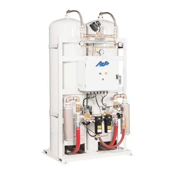
Product o/p Manifold Pressure Transducer Pressure Transducer for Bed A (PT3) for Bed A (PT2) Pressure Transducer Control Panel for Bed A (PT4) Feed & Waste Manifold Filter Assembly Figure 4.1: External Components — Front View AS-Q—AS-Z Series Instruction Manual... -
Page 18: Adsorbers
Coalescing Filter Drain (V-D2) This automatic valve removes moisture from the coalescing filter. Manual Feed #1 Valve (V-1) This manual valve (if available) controls the flow of feed air from the air compressor to the filter assembly. AS-Q—AS-Z Series Instruction Manual... -
Page 19: Pressure Switch Sub-Assembly
The product output sub-assembly directs the oxygen flow to the oxygen receiver and the pressure transducer (PT4). Connects to Equalization Manifold Outlet Outlet for Oxygen Hose Connection Manual Valve for PT4 Manual Valve for Calibration of PT4 Figure 4.3: Typical Product Output Sub-assembly AS-Q—AS-Z Series Instruction Manual... - Page 20 This manual valve controls the flow of oxygen to the pressure transducer (PT4) on the oxygen generator. The valve should not be closed at any circumstance while the unit is running except for the purpose of calibration. AS-Q—AS-Z Series Instruction Manual...
-
Page 21: Feed And Waste Manifold Assembly
Vent Silencers The vent silencers muffle the sound of the waste gas as it exits the adsorbers. Cycle Pressure Gauge The cycle pressure gauge indicates the pressure of the feed air before the air enters the adsorbers. AS-Q—AS-Z Series Instruction Manual... -
Page 22: Equalization And Purge Manifold Assembly
AirSep Corporation Feed Air Regulator The feed air regulator is set at the AirSep Corporation factory. It controls the maximum oxygen generator cycle pressure. The setting of the regulator is customized as per the demand of oxygen for your application. Please ensure that the feed air regulator setting is not changed before consulting AirSep Corporation. -
Page 23: Control Panel: External Components
In order to make the software simple to use, the various screens follow a consistent template design. Each screen consists of two components: the title bar and the information display. Figure 4.5: Typical Main System Control Screen AS-Q—AS-Z Series Instruction Manual... - Page 24 The title bar serves two purposes. It identifies the screen that is currently being displayed. It also acts as the main navigational tool. No matter which screen is being currently displayed, touching the AirSep logo will display the Main System Control screen.
- Page 25 Figure 4.6 below shows the layout of all the screens in HMI for easy navigation. Oxygen Generator Bed Pressure Graphs Main System Control Output Parameters Output Pressure Graphs Bed Pressure Calibration Receiver Calibration Figure 4.6: HMI Navigation Layout AS-Q—AS-Z Series Instruction Manual...
- Page 26 In the MANUAL position, the oxygen generator cycles continuously. The symbol ‘A’ at the right side of the ‘AUTO/MAN’ switch appears only when the oxygen generator is in AUTO mode. The ‘MANUAL DRAIN’ icon activates the drain valve when pressed. Figure 4.7: Typical Oxygen Generator Screen AS-Q—AS-Z Series Instruction Manual...
- Page 27 Message Displays. Figure 4.8: Typical Parameters and Output Screen The ‘Bed Pressure Graphs’ icon takes to the Bed Pressure Graphs Screen as shown. Figure 4.9: Typical Bed Pressure Graphs Screen AS-Q—AS-Z Series Instruction Manual...
- Page 28 The ‘Calibrate Pressure Transducers’ icon displays a screen dedicated to the pressure transducers calibration and settings as shown below. Figure 4.10: Typical Bed Pressure Calibration Screen Manual Valve for Calibration (V-B) Gas Supply Inlet through Generator Figure 4.11: Feed Air Pressure Transducer Assembly AS-Q—AS-Z Series Instruction Manual...
- Page 29 8. Close the manual valve (V-B) and take out the compressed air supply. 9. Open the manual valve (V-A) and resume the normal operation. Press the ‘NEXT’ icon to navigate the calibration screen for the next pressure transducer. AS-Q—AS-Z Series Instruction Manual...
-
Page 30: Control Panel: Internal Components
The internal layout of the control panel mainly consists of the programmable logic controller (PLC), oxygen concentration board (optional), HMI, circuit breakers, transformers, and an alarm horn. Programmable Logic Controller The programmable logic controller contains the logic for the oxygen generator operation. AS-Q—AS-Z Series Instruction Manual... - Page 31 ~1 psig for accurate readings. Refer to Figure 4.1 for the location of the regulator. Human Machine Interface (HMI) The HMI acts as an interface between the operator and the oxygen generator. AS-Q—AS-Z Series Instruction Manual...
-
Page 33: 5.0 Installation
5.0 Installation HANDLING AND UNPACKING AirSep Corporation ships the oxygen generator on a wooden skid along with the filter assembly. In the AS-Z series models, vent silencer assembly is also shipped apart from the oxygen generator and filter assembly. The oxygen receiver, if supplied, is also shipped on a separate skid. -
Page 34: Pre-Installation Guidelines
Appendix of this instruction manual; however, use of such feed air may require modification of the oxygen generator at the AirSep Corporation factory to ensure the product oxygen meets the specifications. Consult your sales representative to determine whether your oxygen generator requires modifications for your application. -
Page 35: Installation Instructions
Airsep oxygen generators are intended to be secured to the floor. Failure to do so can result in the unit tipping over. An example of securing to the floor would be bolting the unit down. - Page 36 Take care not to damage the gasket between the flanges during installation. 6. Install your oxygen receiver supplied by AirSep Corporation. If AirSep Corporation supplied the oxygen receiver, install a relief valve and oxygen outlet manifold to complete its assembly.
- Page 37 7. Install the oxygen regulator assembly on the oxygen receiver. 8. Connect the #4 oxygen concentration sample line to the oxygen receiver and the control panel. Sample pressure set at ~1-2 psig Sample line is connected here Figure 5.2: Oxygen Sample Control Panel Connection AS-Q—AS-Z Series Instruction Manual...
- Page 38 If electrical power is off while your application uses oxygen, the oxygen receiver depressurizes. Provide proper voltage to the oxygen generator. Improper voltage causes damage not covered under the AirSep Corporation Product Warranty. AS-Q—AS-Z Series Instruction Manual...
-
Page 39: 6.0 Operation
Appendix D of this instruction manual before you attempt to start the oxygen generator. Also read and thoroughly understand any literature or instruction manuals for components not provided by the AirSep Corporation. Oxygen vigorously accelerates the burning of combustible materials. -
Page 40: Initial Start-Up
If a shutdown condition exists, pressing the ‘ALARM RESET’ will not reset the system. The ‘ALARM RESET’ icon disappears once all the alarm and shutdown conditions have been rectified. AS-Q—AS-Z Series Instruction Manual... - Page 41 75% open. Allow the unit to run this way until the bed pressures reach a maximum of 70-75 psig each cycle. This will take approximately an additional 5 minutes. AS-Q—AS-Z Series Instruction Manual...
-
Page 42: Operation
To use product oxygen that meets the specifications for your model listed in the Appendix A of this instruction manual, set the AUTO/MANUAL icon on the ‘Oxygen Generator Screen’ to AUTO to produce oxygen only during times of the oxygen demand. AS-Q—AS-Z Series Instruction Manual... -
Page 43: Shutdown
When the feed air pressure exceeds the minimum feed air pressure specified in this instruction manual, press the ‘START’ icon on the Main System Control Screen. Fully open the MANUAL PRODUCT valve (V-3) and the product sample valve. AS-Q—AS-Z Series Instruction Manual... -
Page 44: Extended Shutdown
Using the oxygen generator at flows higher than 15% above those specified in Appendix A of this manual, will result in the likely contamination of the molecular sieve beds. This damage is not covered under the standard warranty. AS-Q—AS-Z Series Instruction Manual... -
Page 45: 7.0 Maintenance
4. Press the manual override buttons on the automatic drain valves on both filters to test the operation of the drain valves. Air or condensate should discharge from the outlets on the drain valves. AS-Q—AS-Z Series Instruction Manual... -
Page 46: Semi-Annual Maintenance
The life of the particulate filter depends on air and piping quality. The particulate filter has a rating of 5 microns. Follow all steps in Section 6.6 — Extended Shutdown. Follow all steps in Section 6.2 — Initial Start-Up. AS-Q—AS-Z Series Instruction Manual... -
Page 47: Annual Maintenance
The expected life of the coalescing filter is approximately one year with proper maintenance of the particulate filter. The coalescing filter has a rating of 0.01 microns. 1. Follow all steps in Section 6.6 — Extended Shutdown. AS-Q—AS-Z Series Instruction Manual... - Page 48 16. Apply soapy water to check for leaks on all fittings loosened during the replacement procedure. 17. Press the manual override button on the automatic drain valve on the coalescing filter and make sure the exhaust contains no liquid. AS-Q—AS-Z Series Instruction Manual...
- Page 49 AirSep Corporation 18. Follow all steps in Section 6.2 — Initial Start-Up. AS-Q—AS-Z Series Instruction Manual...
-
Page 51: 8.0 Troubleshooting
Only trained personnel may open the oxygen generator. The AirSep PSA Oxygen Generator is pressurized during normal operation. You must depressurize the oxygen generator before you attempt any repairs. TECHNICAL SUPPORT... -
Page 52: Troubleshooting Chart
Inadequate cycle Adjust or replace feed specified pressure. pressure. air regulator. Check oxygen usage or Oxygen demand check unit and oxygen exceeds oxygen hoses and piping for generator capacity. leaks. AS-Q—AS-Z Series Instruction Manual... - Page 53 Repair or replace wire. to valve. Defective PLC. (No Replace PLC. power output to valve.) Valve remains Check the valve or the energized and open. PLC output LED. Defective valve. Rebuild valve. Worn internal parts on Rebuild valve. valve. AS-Q—AS-Z Series Instruction Manual...
- Page 54 PLC. Feed air regulator leaks Clean and lubricate Stuck feed air regulator out bleed orifice. main regulator valve main valve assembly. assembly. Defective main valve Rebuild or replace assembly seat. regulator. AS-Q—AS-Z Series Instruction Manual...
- Page 55 Filter drain valve Drain valve obstructed energizes with unit or stuck in closed Clean or replace valve. pressurized, but no air position. exhausts. Drain tubing obstructed Clean or replace tubing. or pinched. AS-Q—AS-Z Series Instruction Manual...
-
Page 57: Appendix Technical Data
Appendix Technical Data SPECIFICATIONS Data in this section refer to standard AS-Q through AS-Z model oxygen generators. The oxygen generators may use feed air at specifications outside those shown; however, use of such feed air may require modification of the oxygen generators at the AirSep Corporation factory to ensure the product oxygen meets the design specifications. - Page 58 1 atmosphere and 0°C / LPM (Liters per minute) gas measured at 1 atmosphere and 21°C. **Check the label on the control panel for appropriate power supply. ***Data may vary as per the customer’s requirements. Table A.1: AS-Q Specifications AS-Q—AS-Z Series Instruction Manual...
- Page 59 1 atmosphere and 0°C / LPM (Liters per minute) gas measured at 1 atmosphere and 21°C. **Check the label on the control panel for appropriate power supply. ***Data may vary as per the customer’s requirements. Table A.2: AS-R Specifications AS-Q—AS-Z Series Instruction Manual...
- Page 60 1 atmosphere and 0°C / LPM (Liters per minute) gas measured at 1 atmosphere and 21°C. **Check the label on the control panel for appropriate power supply. ***Data may vary as per the customer’s requirements. Table A.3: AS-W Specifications AS-Q—AS-Z Series Instruction Manual...
- Page 61 1 atmosphere and 0°C / LPM (Liters per minute) gas measured at 1 atmosphere and 21°C. **Check the label on the control panel for appropriate power supply. ***Data may vary as per the customer’s requirements. Table A.4: AS-Z Specifications AS-Q—AS-Z Series Instruction Manual...
- Page 62 Low oxygen concentration alarm Low oxygen concentration shutdown setpoint Time delay for concentration shutdown at 1 hour start-up Cycle pressure/feed air regulator setting 70-75 psig Oxygen sample line pressure regulator setting 1 psig Table A.5: Typical System Set points AS-Q—AS-Z Series Instruction Manual...
-
Page 63: Drawings And Schematics
AirSep Corporation DRAWINGS AND SCHEMATICS Figure A.1: Typical Pressure Profile and Valves Cycle Sequence AS-Q—AS-Z Series Instruction Manual... - Page 64 AirSep Corporation Figure A.2: Typical Installation Arrangement AS-Q—AS-Z Series Instruction Manual...
- Page 65 AirSep Corporation Figure A.3: General Arrangement Drawing – AS-Q AS-Q—AS-Z Series Instruction Manual...
- Page 66 AirSep Corporation Figure A.4: General Arrangement Drawing – AS-R AS-Q—AS-Z Series Instruction Manual...
- Page 67 AirSep Corporation Figure A.5: General Arrangement Drawing – AS-W AS-Q—AS-Z Series Instruction Manual...
- Page 68 AirSep Corporation Figure A.6: General Arrangement Drawing – AS-Z AS-Q—AS-Z Series Instruction Manual...
- Page 69 AirSep Corporation Figure A.7: P&ID Drawing – AS-Q, AS-R, AS-W and AS-Z AS-Q—AS-Z Series Instruction Manual...
- Page 70 AirSep Corporation Figure A.8: Electrical Schematic – Sheet 1 AS-Q—AS-Z Series Instruction Manual...
-
Page 71: Electrical Schematics - As-Q - As-Z
AirSep Corporation ELECTRICAL SCHEMATICS – AS-Q – AS-Z Figure A.9: Electrical Schematic – Sheet 2 AS-Q—AS-Z Series Instruction Manual... - Page 72 AirSep Corporation Figure A.10: Figure A.10: Electrical Schematic – Sheet 3 AS-Q—AS-Z Series Instruction Manual...
- Page 73 AirSep Corporation Figure A.11: Electrical Schematic – Sheet 4 AS-Q—AS-Z Series Instruction Manual...
-
Page 75: Appendix Warranty/Returns
Each unit of equipment for which a warranty claim is asserted shall, at the request of AirSep, be returned on a prepaid basis with proof of purchase date to the AirSep factory specified by AirSep at the expense of the original purchaser. Replacement parts shall be warranted as stated above for the unexpired portion of the original warranty. -
Page 76: Limits Of Liability
THAT THE SOLE AND EXCLUSIVE REMEDY FOR ANY DEFECT IN PARTS OR WORKMANSHIP IS LIMITED TO ENFORCEMENT OF AIRSEP’S OBLIGATIONS AS SET FORTH ABOVE, AND AIRSEP SHALL NOT BE LIABLE TO ORIGINAL PURCHASER OR ANY OTHER PARTY FOR LOSS OF USE OF THE EQUIPMENT,... - Page 77 AirSep Corporation AirSep Corporation accepts no item(s) for service or credit unless prior written authorization was issued by AirSep Corporation. 3. Return item(s) in their original packaging material. Pack merchandise for a safe return. AirSep Corporation assumes no responsibility for damage that occurs in transit.
-
Page 79: Appendix Component Literature
AirSep Corporation Appendix Component Literature PROGRAMMABLE LOGIC CONTROLLER ■ Schneider Modicon M221 Data Sheets AS-Q—AS-Z Series Instruction Manual... - Page 80 AirSep Corporation AS-Q—AS-Z Series Instruction Manual...
- Page 81 AirSep Corporation AS-Q—AS-Z Series Instruction Manual...
- Page 82 AirSep Corporation AS-Q—AS-Z Series Instruction Manual...
- Page 83 AirSep Corporation AS-Q—AS-Z Series Instruction Manual...
- Page 84 AirSep Corporation AS-Q—AS-Z Series Instruction Manual...
- Page 85 AirSep Corporation AS-Q—AS-Z Series Instruction Manual...
- Page 86 AirSep Corporation AS-Q—AS-Z Series Instruction Manual...
- Page 87 AirSep Corporation AS-Q—AS-Z Series Instruction Manual...
- Page 88 AirSep Corporation AS-Q—AS-Z Series Instruction Manual...
- Page 89 AirSep Corporation AS-Q—AS-Z Series Instruction Manual...
- Page 90 AirSep Corporation AS-Q—AS-Z Series Instruction Manual...
- Page 91 AirSep Corporation AS-Q—AS-Z Series Instruction Manual...
- Page 92 AirSep Corporation AS-Q—AS-Z Series Instruction Manual...
- Page 93 AirSep Corporation AS-Q—AS-Z Series Instruction Manual...
- Page 94 AirSep Corporation AS-Q—AS-Z Series Instruction Manual...
- Page 95 AirSep Corporation AS-Q—AS-Z Series Instruction Manual...
- Page 96 AirSep Corporation TOUCHSCREEN ■ Schneider Electric Magelis HMISTU855 Data sheets AS-Q—AS-Z Series Instruction Manual...
- Page 97 AirSep Corporation AS-Q—AS-Z Series Instruction Manual...
- Page 98 AirSep Corporation AS-Q—AS-Z Series Instruction Manual...
- Page 99 AirSep Corporation AS-Q—AS-Z Series Instruction Manual...
- Page 100 AirSep Corporation AS-Q—AS-Z Series Instruction Manual...
- Page 101 AirSep Corporation AS-Q—AS-Z Series Instruction Manual...
- Page 102 AirSep Corporation AS-Q—AS-Z Series Instruction Manual...
- Page 103 AirSep Corporation AS-Q—AS-Z Series Instruction Manual...
- Page 104 AirSep Corporation FILTERS ■ Wilkerson Filter Models F35, F36, and F37 Installation and Maintenance Sheet AS-Q—AS-Z Series Instruction Manual...
- Page 105 EXTRA COPIES OF THESE INSTRUCTIONS ARE AVAILABLE FOR 4. The drain line connection is dependent on the type of drain that is INCLUSION IN EQUIPMENT / MAINTENANCE MANUALS THAT UTILIZE selected. THESE PRODUCTS. CONTACT YOUR LOCAL REPRESENTATIVE. AS-Q—AS-Z Series Instruction Manual...
- Page 106 Mounting Block Filter Bowl O-ring * CAUTION: Use special 60 mm (long) screw to mount gauge to filter only. Use 3/8" 3. Replace coalescing element when differential pressure reaches or 10mm Flex Tubing the red band. AS-Q—AS-Z Series Instruction Manual...
- Page 107 AirSep Corporation ■ Wilkerson Filter Models M35, M36, and M37 Installation and Maintenance Sheet AS-Q—AS-Z Series Instruction Manual...
- Page 108 3. Install the unit with the air flowing in the direction indicated by the INCLUSION IN EQUIPMENT / MAINTENANCE MANUALS THAT UTILIZE arrow on the body and / or the Differential Pressure Indicator. THESE PRODUCTS. CONTACT YOUR LOCAL REPRESENTATIVE. AS-Q—AS-Z Series Instruction Manual...
- Page 109 24 VDC 5 psig 300 psig X20-04-EE00 1/2" NPT 7/16" 115 VAC/1Ph/50-60Hz 2 psig 300 psig X20-04-ED00 1/2" NPT 7/16" 230 VAC/1PH/50-60Hz 2 psig 300 psig X20-04-EC00 1/2" NPT 7/16" 24 VDC 5 psig 300 psig AS-Q—AS-Z Series Instruction Manual...
- Page 110 AirSep Corporation ■ Wilkerson Filter Model F43 Installation and Maintenance Sheet AS-Q—AS-Z Series Instruction Manual...
- Page 111 Safety Guide section of Pneumatic Division catalogs or you can download the EXTRA COPIES OF THESE INSTRUCTIONS ARE AVAILABLE FOR Pneumatic Division Safety Guide at: www.wilkersoncorp.com INCLUSION IN EQUIPMENT / MAINTENANCE MANUALS THAT UTILIZE THESE PRODUCTS. CONTACT YOUR LOCAL REPRESENTATIVE. AS-Q—AS-Z Series Instruction Manual...
- Page 112 Flex Tubing Screws O-ring (Torque 54 ± 2 FT.- L B.) (8 Required) Automatic Mechanical Drain (Optional) O-ring Drain Plate Drain Plate Screws (Torque 16± 2 FT.-LB.) Screws (6 Required) (6 Required) Nut (For Auto Drain) AS-Q—AS-Z Series Instruction Manual...
- Page 113 AirSep Corporation ■ Wilkerson Filter Models M43 & M45 Installation and Maintenance Sheet AS-Q—AS-Z Series Instruction Manual...
- Page 114 3. Install the unit with the air flowing in the direction indicated by the INCLUSION IN EQUIPMENT / MAINTENANCE MANUALS THAT UTILIZE arrow on the body and / or the Differential Pressure Indicator. THESE PRODUCTS. CONTACT YOUR LOCAL REPRESENTATIVE. AS-Q—AS-Z Series Instruction Manual...
- Page 115 5 psig 300 psig Nut (For Auto Drain) X20-04-EE00 1/2" NPT 7/16" 115 VAC/1Ph/50-60Hz 2 psig 300 psig X20-04-ED00 1/2" NPT 7/16" 230 VAC/1PH/50-60Hz 2 psig 300 psig X20-04-EC00 1/2" NPT 7/16" 24 VDC 5 psig 300 psig AS-Q—AS-Z Series Instruction Manual...
- Page 116 AirSep Corporation PRESSURE TRANSDUCER ■ Measurement Specialties, Inc. – MSI MSP-300 Stainless Steel Isolated Pressure Transducer AS-Q—AS-Z Series Instruction Manual...
- Page 117 Pumps and Compressors customization needs. Hydraulic/Pneumatic Systems Automotive Test Systems Energy and Water Management Medical Gas Pressure Leak Detection Remote Measuring Systems General Pressure Measurements SENSOR SOLUTIONS ///MSP300 Page 1 09/2017 AS-Q—AS-Z Series Instruction Manual...
- Page 118 50g, 11 msec Half Sine Shock per MIL-STD-202G, Method 213B, Condition A Vibration ±20g, MIL-STD-810C, Procedure 514.2-2, Curve L Wetted Material (except elastomer seal) 17-4PH or 316L Stainless Steel For custom configurations, consult factory. 11/2017 SENSOR SOLUTIONS ///MSP300 Page 2 AS-Q—AS-Z Series Instruction Manual...
- Page 119 Reflect pressure port diaphragm temperature over the compensated temperature range. Response time is from power on to reading measurement data. Maximum cable length for I C output is 10meter and 2.5meter for SPI output. 11/2017 SENSOR SOLUTIONS ///MSP300 Page 3 AS-Q—AS-Z Series Instruction Manual...
- Page 120 9 – 30V +Supply -Supply Cut Off Cut Off OUTPUT (DIGITAL) Code Output Supply Black Green White Yellow 2.7 – 5.0V +Supply -Supply 2.7 – 5.0V +Supply -Supply SCLK MISO 11/2017 SENSOR SOLUTIONS ///MSP300 Page 4 AS-Q—AS-Z Series Instruction Manual...
- Page 121 AirSep Corporation MSP300 Pressure Transducer PRESSURE OUTPUT 11/2017 SENSOR SOLUTIONS ///MSP300 Page 5 AS-Q—AS-Z Series Instruction Manual...
- Page 122 AirSep Corporation MSP300 Pressure Transducer TEMPERATURE OUTPUT 11/2017 SENSOR SOLUTIONS ///MSP300 Page 6 AS-Q—AS-Z Series Instruction Manual...
- Page 123 Users of TE Connectivity products should make their own evaluation to determine the suitability of each such product for the specific application. © 2015 TE Connectivity Ltd. family of companies All Rights Reserved. 11/2017 SENSOR SOLUTIONS ///MSP300 Page 7 AS-Q—AS-Z Series Instruction Manual...
- Page 124 AirSep Corporation ■ Measurement Specialties, Inc. – MSI MSP-300-150-P-4-N-X-XXX Pressure Transducer Drawing AS-Q—AS-Z Series Instruction Manual...
- Page 125 AirSep Corporation AS-Q—AS-Z Series Instruction Manual...
- Page 126 AirSep Corporation VALVES AND ACTUATORS ■ Neles-Jamesbury IMO 308 Model C Wafer-Sphere® Butterfly Valves Installation, Maintenance and Operating Instructions AS-Q—AS-Z Series Instruction Manual...
- Page 127 AirSep Corporation Wafer-Sphere® Butterfly Valve Model C 2 1/2” - 24” (DN65 - 600) Class 150 & 300 Installation, Maintenance and Operating Instructions AS-Q—AS-Z Series Instruction Manual...
- Page 128 These instructions provide information about safe handling and operation of the valve. If you require additional assistance, please contact the manufacturer or manufacturer’s representative. Addresses and phone numbers are printed on the back cover. See also www.metso.com/valves for the latest documentation. SAVE THESE INSTRUCTIONS! IMO 1/18 AS-Q—AS-Z Series Instruction Manual...
-
Page 129: General
Clockwise gasket surface. Damage to body seals can result if snap-in inserts are not clamped when valve is cycled. Open Always Counterclockwise HANDLE DIRECTION VALVE CLOSED Positive Stop Offset Shaft Operatio Figure 1 IMO 1/18 AS-Q—AS-Z Series Instruction Manual... -
Page 130: Valve Markings
AND MAKE SURE SPRINGS IN SPRING-RETURN ACTUATORS ARE IN THE FULL EXTENDED/RELAXED STATE BEFORE PERFORMING Single Flange Body Design ANY VALVE MAINTENANCE. FAILURE TO DO THIS MAY RESULT IN Figure 3 DAMAGE OR PERSONAL INJURY! IMO 1/18 AS-Q—AS-Z Series Instruction Manual... -
Page 131: Transportation And Storage
Remove the flow port protectors and check that the valve is clean inside. Clean valve if necessary. Flush the pipeline carefully before installing the valve. Foreign objects, such as sand or pieces of welding electrodes, will damage the disc and seats. IMO 1/18 AS-Q—AS-Z Series Instruction Manual... -
Page 132: Valve Insulation
IN THE BODY CAVITY BEFORE REMOVAL FROM THE PIPELINE. The actuator must not touch the pipeline, because pipeline AFTER REMOVAL AND BEFORE ANY DISASSEMBLY, vibration may interfere with its operation. CYCLE THE VALVE AGAIN SEVERAL TIMES. IMO 1/18 AS-Q—AS-Z Series Instruction Manual... -
Page 133: Actuated Valve
(air-to-close) actuators must be disconnected from the Angled As To Engage Insert Spring actuators and then closed. Valves must be closed while removing them from the pipeline. Tapping Insert Assembly Into Body Insert Removal / Installation Figure 8 IMO 1/18 AS-Q—AS-Z Series Instruction Manual... -
Page 134: Seat Replacement Standard Valves
Be sure the spring is positioned snugly into the groove. Remove the seat (5) and discard. Remove the body seal (40) from the insert and body. IMO 1/18 AS-Q—AS-Z Series Instruction Manual... -
Page 135: Shaft Seal Replacement
Remove the handle or actuator coupling. BOLTED INSERT Remove the nuts (15) from above the compression plate (10). Remove the compression plate (10). The Figure 10 studs (14) do not have to be removed. IMO 1/18 AS-Q—AS-Z Series Instruction Manual... -
Page 136: Valve Disassembly
(Figure 15). Remove screws (55) and cover plate (53), and remove Slide the shaft through the top bearing and engage gasket (54). the top thrust bearing (64). With the two pin holes IMO 1/18 AS-Q—AS-Z Series Instruction Manual... -
Page 137: Testing The Valve
10. If leakage is detected, vent the valve and make an MOUNTING INSTRUCTIONS Section. Tighten the actuator close-stop adjustment as described in the screws holding the ratchet plate. appropriate Jamesbury actuator IMO, listed in Table 4. IMO 1/18 AS-Q—AS-Z Series Instruction Manual... -
Page 138: Manual Handles
PRODUCTS TO INDICATE CORRECT VALVE POSITION COULD RESULT IN DAMAGE OR PERSONAL INJURY. Caution: When installing a linkage or servicing a valve/ actuator assembly, the best practice is to remove the entire Figure 11 assembly from service. IMO 1/18 AS-Q—AS-Z Series Instruction Manual... -
Page 139: Actuator Mounting Instructions
Disc face (or shaft blade) perpendicular with the flange face. Valve Closed: Disc face parallel to flange face within 1/32” (.79 mm). Direct Drive Mounting Follow instructions per Paragraph 6.1 except for coupling Figure 13 assembly. (See Figure 17) IMO 1/18 AS-Q—AS-Z Series Instruction Manual... -
Page 140: Repair Kits
NOTE: When ordering spare parts, always include the following information: Valve catalog code from identification plate, b. If the valve is serialized – the serial number (from identification plate) From Figure 15, the ballooned part number, part name and quantity required. IMO 1/18 AS-Q—AS-Z Series Instruction Manual... - Page 141 Insert Spring (3” - 12” [DN 80 - 300] Wafer Style Only) ** Cap Screw quantities vary by valve, size and Chamfer style + Parts contained in repair kit side down Direction of Installation Toward Stop Figure 15 IMO 1/18 AS-Q—AS-Z Series Instruction Manual...
- Page 142 Lockwasher Thrust Bearing ** Cap Screw quantities vary by valve, size and style + Parts contained in repair kit # Quantities vary by valve size Direction of Installation Toward Stop Figure 15A IMO 1/18 AS-Q—AS-Z Series Instruction Manual...
- Page 143 Bracket Bolting Torques for GR.5 Hex Cap Screws Torque to Aluminum Body Actuators Bolt Size No Lubrication to Screws inches FT•LBS N•m FT•LBS N•m 5/16 7/16 9/16 1-1/8 1-1/4 14.9 19.0 1062 1288 1826 IMO 1/18 AS-Q—AS-Z Series Instruction Manual...
- Page 144 20” (DN 500) 815 RKW-662 RKW-662 RKW-666 RKW-666 20” (DN 500) 830 RKW-676 RKW-676 RKW-671 RKW-671 24” (DN 600) 815 RKW-334 RKW-334 RKW-667 RKW-667 24” (DN 600) 830 RKW-677 RKW-677 RKW-672 RKW-672 OA = ON APPLICATION IMO 1/18 AS-Q—AS-Z Series Instruction Manual...
- Page 145 Monel® is a registered trademark of Special Metals Corporation. 6. sign BODY MATERIAL Carbon Steel (WCB) Alloy 20 (CN7M) Stainless Steel (CF8M) Stainless Steel (CG8M) Monel® (M-35-1) Hastelloy® C (CW-12MW) Other materials available on application. IMO 1/18 AS-Q—AS-Z Series Instruction Manual...
- Page 146 China, 11/F, China Youth Plaza, No.19 North Rd of East 3rd Ring Rd, Chaoyang District, Beijing 100020, China. Tel. +86 10 6566 6600. Fax +86 10 6566 2583 Middle East, Roundabout 8, Unit AB-07, P.O. Box 17175, Jebel Ali Freezone, Dubai, United Arab Emirates. Tel. +971 4 883 6974. Fax +971 4 883 6836 www.metso.com/valves AS-Q—AS-Z Series Instruction Manual...
- Page 147 AirSep Corporation ■ Motivair Automatic Condensate Removal Valve EDM 20-1 Electronic Timer-Solenoid Technical Data AS-Q—AS-Z Series Instruction Manual...
- Page 148 Granzow, Inc.• 2300 Crownpoint Executive Drive, Charlotte, NC 28227-6702 • Phone (704) 845-2300 • Fax (704) 845-2301 ©2012 Granzow, Inc. All rights reserved. Information within this document is subject to change, and may be modified at any time, without notice. AS-Q—AS-Z Series Instruction Manual...
- Page 149 AirSep Corporation ■ ASCO 4-Way 2 Position Single Solenoid Valves — ¼ NPT Pressure Series 8551 Installation and Maintenance Instructions AS-Q—AS-Z Series Instruction Manual...
- Page 150 Port Markings: 1 = Pressure, 2 & 4 = Cylinder 3 & 5 = Exhaust Page 1 of 4 Printed in U.S.A. All Rights Reserved. ASCO Valves 50-60 Hanover Road, Florham Park, New Jersey 07932 www.ascovalve.com AS-Q—AS-Z Series Instruction Manual...
- Page 151 Check catalog number prefix and watt rating on To Engage To Disengage nameplate. Operating Screw Figure 1. Manual Operator (partial view). Page 2 of 4 Form No.V7418 ASCO Valves 50-60 Hanover Road, Florham Park, New Jersey 07932 www.ascovalve.com AS-Q—AS-Z Series Instruction Manual...
- Page 152 3. Install new coil and replace retaining clip. 4. Make electrical hookup to coil. *DuPont's Registered Trademark Form No.V7418 Page 3 of 4 ASCO Valves 50-60 Hanover Road, Florham Park, New Jersey 07932 www.ascovalve.com AS-Q—AS-Z Series Instruction Manual...
- Page 153 Solenoid B Dual Solenoid Construction Figure 3. Series 8551 shown with prefix SC coil. Page 4 of 4 Form No.V7418 ASCO Valves 50-60 Hanover Road, Florham Park, New Jersey 07932 www.ascovalve.com AS-Q—AS-Z Series Instruction Manual...
- Page 154 AirSep Corporation ■ Jamesbury Double-opposed Piston Actuators IMO-528 Installation, Maintenance and Operating Instructions AS-Q—AS-Z Series Instruction Manual...
- Page 155 AirSep Corporation Valv-Powr® VPVL Mod C Value-Line® Double-Opposed Piston Actuators Installation, Maintenance and Operating Instructions AS-Q—AS-Z Series Instruction Manual...
- Page 156 These instructions provide information about safe handling and operation of the valve. If you require additional assistance, please contact the manufacturer or manufacturer’s representative. Addresses and phone numbers are printed on the back cover. See also www.metso.com/valves for the latest documentation. SAVE THESE INSTRUCTIONS! IMO 11/17 AS-Q—AS-Z Series Instruction Manual...
-
Page 157: General
Loss of air pressure allows springs to force pistons toward center position, compressing springs. Exhaust air exits at Port 4 (a position with exhaust air exiting at Port 2 (a clockwise rotation is counterclockwise rotation is obtained). obtained). Figure 2 IMO 11/17 AS-Q—AS-Z Series Instruction Manual... -
Page 158: Operation
02, 04, 03, 11 air supply is disconnected. When the actuator is a spring- return unit, make sure that the actuator is in the failed position before disassembling. Figure 4 IMO 11/17 AS-Q—AS-Z Series Instruction Manual... - Page 159 Cleaning and Inspection. be used to remove the pistons from the body. A. When all components are disassembled, those not being replaced should be properly cleaned and inspected for wear prior to re-assembly. Figure 6 IMO 11/17 AS-Q—AS-Z Series Instruction Manual...
-
Page 160: Assembly
C. Hold the body (50) in a horizontal position by inserting the top of the shaft in a vice, or inserting the bottom of the shaft connection into a male drive fitted into a vice as shown by (Figure 10). IMO 11/17 AS-Q—AS-Z Series Instruction Manual... - Page 161 (Figure 16), using torques listed in engaged, fully compress both pistons (40) inward Table 4. and measure the distance from the edge of the body to the piston (40) face on each side, shown IMO 11/17 AS-Q—AS-Z Series Instruction Manual...
- Page 162 C. When the correct clockwise position is obtained, Tighten cap screw (39) to secure the position hold the adjusting screw (2) stationary while indicator. tightening the lock nut (4). IMO 11/17 AS-Q—AS-Z Series Instruction Manual...
- Page 163 O-ring and washer are in the correct place. When indicator pointer on top of actuator to determine O-ring Washer Travel Stop Screw Stop Screw Type A VPVL 051-300 L Min. Approx L Max. Approx Stop Screw Type B VPVL 350-800 Figure 19 IMO 11/17 AS-Q—AS-Z Series Instruction Manual...
-
Page 164: Safety Lockout Device
Insert the padlock into the hole of the safety cover lock position is achieved then tighten the special (229) and lock it. For safety, keep the padlock key nut (228). in a safe place. IMO 11/17 AS-Q—AS-Z Series Instruction Manual... -
Page 165: Actuator Storage
NOTE: When ordering spare parts, always include the following information: Actuator catalog code from label, b. If the actuator is serialized – the serial number (from identification plate) From Figure 23, the ballooned part number, part name and quantity required. IMO 11/17 AS-Q—AS-Z Series Instruction Manual... - Page 166 AirSep Corporation IMO-528 EN EXPLODED VIEW 50 41 10 18 39 * Suggested Spare Parts for Maintenance Figure 23 IMO 11/17 AS-Q—AS-Z Series Instruction Manual...
- Page 167 Cap Screw (Indicator) Stainless Steel ISO 3506 Pistons Aluminum UNI 5075 Anodized Actuator Identification Label Polyester Aluminum End Cap Label Polyester Aluminum Body Aluminum ASTM B221 Anodized PTFE-Coated Drive Shaft Carbon Steel Plated ASTM A105 IMO 11/17 AS-Q—AS-Z Series Instruction Manual...
- Page 168 IMO-528 EN TABLE 4 VPVL END CAP TORQUE VALUES End Cap Metric Torque Torque Torque Bolt Size Wrench Size in-lbs ft-lbs VPVL051 VPVL100 VPVL200 VPVL250 VPVL300 VPVL350 VPVL400 VPVL450 VPVL500 VPVL550 VPVL600 VPVL650 VPVL700 IMO 11/17 AS-Q—AS-Z Series Instruction Manual...
- Page 169 Series+ Valv-Powr Value-Line Double-Acting Piston Actuator Model SR4/5 Spring-Return 60-psi (4.1 bar) Spring-to-Close (CW Rotation) Model C Spring-Return 80-psi (5.5 bar) Spring-to-Close (CW Rotation) + Other spring rates on application Modifier Code — Standard IMO 11/17 AS-Q—AS-Z Series Instruction Manual...
- Page 170 China, 11/F, China Youth Plaza, No.19 North Rd of East 3rd Ring Rd, Chaoyang District, Beijing 100020, China. Tel. +86 10 6566 6600. Fax +86 10 6566 2583 Middle East, Roundabout 8, Unit AB-07, P.O. Box 17175, Jebel Ali Freezone, Dubai, United Arab Emirates. Tel. +971 4 883 6974. Fax +971 4 883 6836 www.metso.com/valves AS-Q—AS-Z Series Instruction Manual...
- Page 171 AirSep Corporation PRESSURE SWITCH ■ Allen-Bradley Bulletin 836 Style C Instruction Sheet AS-Q—AS-Z Series Instruction Manual...
- Page 172 AirSep Corporation AS-Q—AS-Z Series Instruction Manual...
- Page 173 AirSep Corporation AS-Q—AS-Z Series Instruction Manual...
- Page 174 AirSep Corporation MAGNALUBE-G ■ Saunders Enterprises, Inc. Grease for Feed Air Regulators Material Safety Data Sheet` AS-Q—AS-Z Series Instruction Manual...
- Page 175 Linden, NJ 07036 Phone: 1-718-729-1000 Fax: 1-718-729-2690 Emergency Telephone: U.S. and Canada: 1-718-729-1000 Outside the U.S. and Canada: info@magnalube.com Date of Issue: 05/15/2015. Magnalube® is a registered trademark of Magnalube, Inc., the exclusive manufacturer of Magnalube greases. AS-Q—AS-Z Series Instruction Manual...
- Page 176 Continue rinsing for at least 10 minutes. Get medical attention if irritation persists. Storage: Not applicable. Disposal: Not applicable. Hazards not otherwise classified: None known. SECTION 3: COMPOSITION/INFORMATION ON INGREDIENTS Ingredient Name: Highly Refined Mixture: Lubricating Oils, Petroleum, Base Oils. Substance/mixture: Mixture. Other means of identification: Not available. AS-Q—AS-Z Series Instruction Manual...
- Page 177 If material has been swallowed and the exposed person is conscious, give small quantities of water to drink. Do not induce vomiting unless directed to do so by medical personnel. Get medical attention if symptoms occur. AS-Q—AS-Z Series Instruction Manual...
- Page 178 No action shall be taken involving any personal risk or without suitable training. Special Protective Equipment for Firefighters: Fire-fighters should wear appropriate protective equipment and self-contained breathing apparatus (SCBA) with a full face-piece operated in positive pressure mode. AS-Q—AS-Z Series Instruction Manual...
- Page 179 Workers should wash hands and face before eating, drinking and smoking. Remove contaminated clothing and protective equipment before entering eating areas. Note: See also Section 8 for additional information on hygiene measures. AS-Q—AS-Z Series Instruction Manual...
- Page 180 If contact is possible, the following protection should be worn, unless the assessment indicates a higher degree of protection: safety glasses with side- shields. AS-Q—AS-Z Series Instruction Manual...
- Page 181 Flammibility (solid, gas): Flammable in the presence of the following materials or conditions: open flames, sparks and static discharge. Lower and Upper Explosive (Flammable) Limits: Not applicable. Vapor Pressure: Not available. Vapor Density: Not available. Relative Density: 0.89 g/cm³. Solubility: Insoluble in water. Partition Coefficient n-octanol/Water: Not available. AS-Q—AS-Z Series Instruction Manual...
- Page 182 SYMPTOMS RELATED TO THE PHYSICAL, CHEMICAL AND TOXICOLOGICAL CHARACTERISTICS : Inhalation: No specific data. Ingestion: No specific data. Skin contact: Adverse symptoms may include the following: irritation, redness. Eye contact: Adverse symptoms may include the following: pain or irritation, watering, redness. AS-Q—AS-Z Series Instruction Manual...
- Page 183 TERATOGENICITY : Conclusion/Summary: There are no data available on the mixture itself. Teratogenicity not suspected for humans. SPECIFIC TARGET ORGAN TOXICITY (SINGLE EXPOSURE) : Not available. SPECIFIC TARGET ORGAN TOXICITY (REPEATED EXPOSURE) : Not available. AS-Q—AS-Z Series Instruction Manual...
- Page 184 Carcinogenicity: No known significant effects or critical hazards. Mutagenicity: No known significant effects or critical hazards. Teratogenicity: No known significant effects or critical hazards. Developmental effects: No known significant effects or critical hazards. Fertility effects: No known significant effects or critical hazards. AS-Q—AS-Z Series Instruction Manual...
- Page 185 Disposal of this product, solutions and any by-products should at all times comply with the requirements of environmental protection and waste disposal legislation and any regional local authority requirements. Waste packaging should be recycled. Incineration or AS-Q—AS-Z Series Instruction Manual...
- Page 186 TSCA 8(a) CDR Exempt/Partial exemption: Not determined United States inventory (TSCA 8b): All components are listed or exempted. Clean Air Act Section 112: Not listed. (b) Hazardous Air Pollutants (HAPs) Clean Air Act Section 602: Not listed. AS-Q—AS-Z Series Instruction Manual...
- Page 187 No listed substance SARA 313 notifications must not be detached from the SDS and any copying and redistribution of the SDS shall include copying and redistribution of the notice attached to copies of the SDS subsequently redistributed. AS-Q—AS-Z Series Instruction Manual...
- Page 188 Not listed. Montreal Protocol (Annexes A, B, C, E) : Not listed. INTERNATIONAL LISTS National inventory : Australia: Not determined. China: Not determined. Europe: All components are listed or exempted. Japan: Not determined. Malaysia: Not determined. AS-Q—AS-Z Series Instruction Manual...
- Page 189 HMIS® program. HMIS® is a registered mark of the National Paint & Coatings Association (NPCA). HMIS® materials may be purchased exclusively from J. J. Keller (800) 327-6868. The customer is responsible for determining the PPE code for this material. AS-Q—AS-Z Series Instruction Manual...
- Page 190 NPCA HMIS Hazard Index: Slight; Slightly Toxic - May cause slight irritation (1). Personal Protection Index: B - Safety Eyewear and Gloves. NPCA HMIS Flammability Index: Burns only if pre-heated (1). Tariff Code (Schedule B): 2710.19.3750 Lubricating greases, with or without additives. AS-Q—AS-Z Series Instruction Manual...
- Page 191 Final determination of suitability of any material is the sole responsibility of the user. All materials may present unknown hazards and should be used with caution. Although certain hazards are described herein, we cannot guarantee that these are the only hazards that exist. AS-Q—AS-Z Series Instruction Manual...
- Page 192 AirSep Corporation MISCELLANEOUS ■ Gasket Material for Oxygen Service Durabla Manufacturing Company Durabla Black Compressed Gasket Material Material Safety Data Sheets AS-Q—AS-Z Series Instruction Manual...
- Page 193 AirSep Corporation AS-Q—AS-Z Series Instruction Manual...
- Page 195 2. Decommission Decommissioning of the oxygen generator shall be performed in accordance to the owner’s quality assurance procedures. A typical decommissioning includes the following: ■ Updating the equipment database ■ Removal of maintenance contracts and/or service schedules AS-Q—AS-Z Series Instruction Manual...
- Page 196 3. Scrapping Oxygen generator that cannot be reused shall be scrapped to a scrap metal recycling center following all the governing ordinances and recycling plans. AS-Q—AS-Z Series Instruction Manual...
- Page 197 AirSep Corporation AS-Q—AS-Z Series Instruction Manual...
- Page 198 © 2019 AirSep Corporation. All Rights Reserved. AirSep reserves the right to discontinue its products, or change the prices, materials, equipment, quality, descriptions, specifications and/or processes to its products at any time without prior notice and with no further obligation or consequence.
Need help?
Do you have a question about the AS-Q and is the answer not in the manual?
Questions and answers