Table of Contents
Advertisement
Quick Links
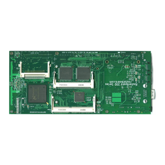
RouterBOARD 200 Series
User's Manual
Rev. Q (22-Nov-2005)
Copyright
Copyright © 2003-2005 MikroTikls SIA. This manual contains information protected by copyright law. No
part of it may be reproduced or transmitted in any form without prior written permission from the
copyright holder.
Trademarks
RouterBOARD, RouterOS, RouterBIOS and MikroTik are trademarks of MikroTikls SIA. All trademarks and
registered trademarks appearing in this manual are the property of their respective holders.
Limited Warranty
Hardware. MikroTikls SIA warrants all RouterBOARD 200 series equipment for the term of one year from
the shipping date to be free of defects in materials and workmanship under normal use and service. All
parts will be repaired or replaced with similar or functionally equivalent parts by MikroTikls SIA during the
warranty term, except in case the returned parts have mechanical, electrical or other accidental or
intended damages caused by improper use or due to wind, rain, fire or other acts of nature.
Parts (or systems) must be shipped pre-paid to our facility in Riga, Latvia. All items must have a Return
Material Authorization (RMA) which you can get by contacting us via email, telephone or fax. RMA must
be printed, signed, and enclosed with the shipment, also the RMA number must be written on the
package itself. Parts sent without following the proper procedure will be treated as those not to be
repaired or replaced due to the above mentioned conditions. Items proved to be free of defects in our lab
will be returned to the customer at the customer's expense. Those that do meet the warranty repair
requirements will be repaired or replaced, and returned to the customer's location at our expense,
extending the warranty term for the time the items are being shipped to and from our facility and
replaced or repaired.
Manual. This manual is provided "as is" without a warranty of any kind, expressed or implied, including,
but not limited to, the implied warranty of merchantability and fitness for a particular purpose. The
manufacturer has made every effort to ensure the accuracy of the contents of this manual, however, it is
possible that it may contain technical inaccuracies, typographical or other errors. No liability is assumed
for any inaccuracy found in this publication, nor for direct or indirect, incidental, consequential or other
damages that may result from such an inaccuracy, including, but not limited to, loss of data or profits.
Caution
To avoid damage of the system, use the correct DC input voltage range.
Advertisement
Table of Contents

Related Manuals for MikroTik RouterBOARD 230


Summarization of Contents
Copyright, Trademarks, and Warranty
Copyright and Trademark Notices
States copyright holder, usage restrictions, and lists registered trademarks.
Limited Hardware Warranty
Details hardware warranty coverage and limitations for defects and damage.
Manual Warranty and Caution
States manual warranty terms and provides caution on DC input voltage.
System Board View: RouterBOARD 230
Top View Diagram
Diagram showing the top layout of the RouterBOARD 230 system board.
Bottom View Diagram
Diagram illustrating the bottom layout of the RouterBOARD 230 system board.
System Board View: RouterBOARD 220
Top View Diagram
Diagram showing the top layout of the RouterBOARD 220 system board.
Bottom View Diagram
Diagram illustrating the bottom layout of the RouterBOARD 220 system board.
System Board Layout
Top View Layout Details
Diagram detailing components and connectors on the top side of the system board.
Bottom View Layout Details
Diagram detailing components and connectors on the bottom side of the system board.
Block Diagram
System Architecture Overview
Illustrates the main components and their interconnections within the system.
Specifications Overview
RouterBOARD 220 Specifications
Detailed technical specifications for the RouterBOARD 220 model.
RouterBOARD 230 Specifications
Detailed technical specifications for the RouterBOARD 230 model.
Hardware Guide
Memory and Storage Devices
Information on supported SoDIMM memory, CompactFlash, and ATA interfaces.
Extension Slots
Details on PCI, MiniPCI, and PCMCIA slots and their compatibility.
Input/Output Ports
LAN, USB, and Serial Ports
Description of LAN1 (with PoE), LAN2, USB, and DB9 serial ports.
Other Interface Connectors
Details on GPIO, ACCESS.bus, Intrusion Detection, LCD Out, and LPC interfaces.
LEDs, CMOS Battery, and Assembly
LED Indicators and CMOS Battery
Information on user LEDs, MiniUPS LED, Power LED, and CMOS battery function.
Hardware Assembly and Powering
Steps for assembling hardware and connecting power via jack/header or PoE.
Power Consumption and Booting
Power Consumption Details
Presents power consumption figures for different configurations and power sources.
Booting Options and Protocols
Covers RouterBIOS boot options, internal storage, and EtherBoot protocol.
Operating System Compatibility
RouterOS, Linux, BSD, and DOS
Compatibility details for MikroTik RouterOS, Linux, BSD variants, and DOS.
RouterBIOS Functionality
Describes the minimal functionality of RouterBIOS for booting operating systems.
BIOS Management
BIOS License and Boot Errors
Details the BIOS license and how to interpret boot error codes indicated by LEDs.
BIOS Configuration Access
Explains how to access and navigate the BIOS setup menu and its options.
BIOS Configuration Options
Configurable BIOS Parameters
Defines various BIOS settings like boot delay, serial console, memory settings, etc.
PCI Back-off Value Selection
Provides guidance on selecting the PCI Back-off parameter based on hardware.
BIOS Upgrading Procedures
Upgrading via Serial Port
Describes upgrading BIOS using XModem protocol via the serial port.
Upgrading via Disk Image or RouterOS
Explains BIOS upgrades using special disk images or MikroTik RouterOS.
Appendix: Connector Index (J1-J10)
J1-J5 Connector Pinouts
Details pinouts for connectors J1 through J5.
J6-J10 Connector Pinouts
Details pinouts for connectors J6 through J10.
Appendix: Connector Index (J11-J19)
J11-J14 Connector Pinouts
Details pinouts for connectors J11 through J14.
J15-J19 Connector Pinouts
Details pinouts for connectors J15 through J19.
Appendix: JTAG Connector (J20)
J20 JTAG Connector Pinout
Details the pinout and function of the JTAG (IEEE1149.1) connector.
Appendix: Jumpers and Cables
Jumper Index
Explains the function and settings for various jumpers (JP1-JP6).
Cable Pinout Specifications
Provides pinouts and specifications for Ethernet and Serial Console cables.
Need help?
Do you have a question about the RouterBOARD 230 and is the answer not in the manual?
Questions and answers