Advertisement
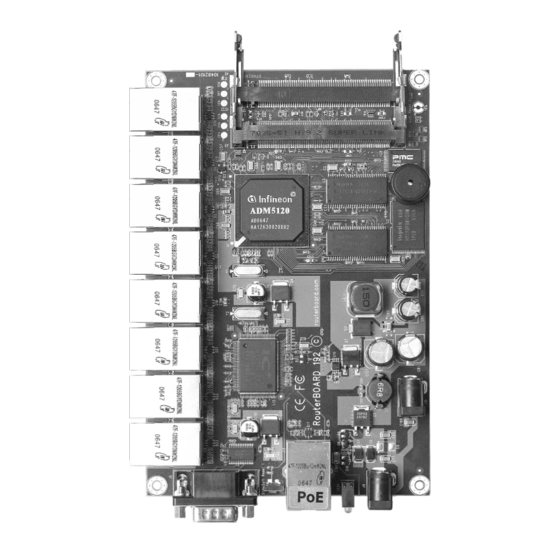
RouterBOARD 192
Quick Setup Guide and Warranty Information
Assembling the Hardware
First use of the board:
●
Insert the MiniPCI cards. RouterBOARD 192 provides two MiniPCI slots.
●
Connect antenna cables to the MiniPCI cards.
●
Install the board in a case and connect other peripherals and cables.
●
Plug in power cable to turn on the board.
Powering
The board accepts powering from either of the two power jacks, or from the LAN1 Ethernet
port:
●
direct-input power jacks J9/J10 (5.5mm outside and 2mm inside diameter, female,
pin positive plug) accept 9..28 V DC (overvoltage protection starts at 30V).
●
LAN1 Ethernet port J13 accepts 9..28 V DC input (at the board; higher voltage
needed to compensate for power loss on long cables – at least 18V suggested) from
non-standard (passive) Power over Ethernet injectors (no power over datalines). The
board does not work with IEEE802.3af compliant 48V power injectors.
CAUTION: all three power inputs are always active, but only one of them may be used at a
time to avoid damage of equipment.
The maximum output of the power supply available for extension cards is normally 6.7W (2.0A).
Booting process
First, RouterBOOT loader is started. It displays some useful information on the onboard RS232C asynchronous serial port.
The serial port is set by default to 115200bit/s, 8 data bits, 1 stop bit, no parity. Note that the device does not fully
implement the hardware (RTS/CTS) flow control, so it is suggested to try to disable hardware flow control in the terminal
emulation program in case the serial console does not work as expected, and if it does not help, make a new cable using the
pinout given in the User's manual. The loader may be configured to boot the system from the onboard NAND, and/or from
network. See the respective section of User's manual on how to configure booting sequence and other BIOS parameters.
DHCP or BOOTP (configurable in loader) protocols allow the RouterBOARD 192 series board to get an initial IP address, and
provide the address of a TFTP server to download an ELF boot image from. It is especially useful for software installation.
See the User's manual for more information and protocol details. Note that you must connect the RouterBOARD you want to
boot and the BOOTP/DHCP and TFTP servers to the same broadcast domain (i.e., there must not be any routers between
them – they must be on the same Ethernet switch).
Extension Slots and Ports
●
Nine Ethernet ports, supporting automatic cross/straight cable correction (Auto MDI/X), so you can use either straight
or cross-over cables for connecting to other network devices. The first Ethernet port (marked with the "PoE" label and
detached from the 8-port block) accepts 9..28 V DC powering from a passive PoE injector. The other eight Ethernet
ports (placed as a block) do not support PoE powering.
●
Two MiniPCI Type IIIA/IIIB ports with 3.3V power signaling.
See
www.routerboard.com
for more information. Contact
support@mikrotik.com
for support questions.
rev. B (5-Nov-2007)
Advertisement
Table of Contents

Related Manuals for MikroTik RouterBOARD 192


Summary of Contents for MikroTik RouterBOARD 192
- Page 1 See the respective section of User's manual on how to configure booting sequence and other BIOS parameters. DHCP or BOOTP (configurable in loader) protocols allow the RouterBOARD 192 series board to get an initial IP address, and provide the address of a TFTP server to download an ELF boot image from. It is especially useful for software installation.
- Page 2 No part of it may be reproduced or transmitted in any form without prior written permission from the copyright holder. RouterBOARD, RouterOS, RouterBOOT and MikroTik are trademarks of MikroTikls SIA. All trademarks and registered trademarks appearing in this manual are the property of their respective holders.
Need help?
Do you have a question about the RouterBOARD 192 and is the answer not in the manual?
Questions and answers