Table of Contents
Advertisement
MCAC-2008-11
Air-cooled Modular Chiller
Contents
1. Nomenclature.......................................................................
2. Product Schedule.................................................................
3. Features..............................................................................
4. Specification........................................................................
5. Dimension...........................................................................
6. Piping Diagrams & Pipe Connection Drawing...........................
7. Wiring Diagrams..................................................................
8. Electric Characteristics..........................................................
9. Capacity Tables..................................................................
10. Exploded View...................................................................
11. Troubleshooting.................................................................
12. Installation.........................................................................
13. Debugging.......................................................................
14. Maintenance......................................................................
15. Control..............................................................................
※ Manufacture reserves the right to discontinue, or change at any time, specifications or designs without
notices and without incurring obligations.
1
Advertisement
Table of Contents

Related Manuals for Midea MGA-D30W/SN1


Summarization of Contents
1. Nomenclature
Model Code Breakdown
Explains the structure and meaning of the model code MGA-D65 W/S N1.
Key Specification Overview
Details key specifications like refrigerant, power supply, compressor type, and application.
2. Product Schedule
Model Specifications Table
Lists various models with their corresponding specifications like refrigerant and power supply.
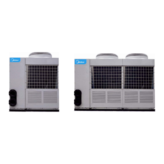
External Appearance Views
Shows visual representations of the 30 kW and 65kW modules.
3. Features
Modular Design and Compressor Technology
Details the flexible modular design, stepless capacity adjustment via digital compressors, and system reliability.
Unit Interconnection and Control System
Explains unit connection methods and key functions of the intelligent micro-computer control system.
4. Specification
30kW Fixed Speed Module Specifications
Covers performance, system parameters, dimensions, weight, wiring, and electricals for 30kW fixed speed units.
High Capacity and 65kW Fixed Speed Specifications
Details specs for higher capacity fixed speed modules and 65kW units, including multi-module configurations.
Digital Scroll Module Specifications
Lists specifications for 30kW and 65kW digital scroll modules, covering performance, components, and electrical data.
High Capacity Digital Scroll System Data
Provides specs for larger digital scroll systems, including combined units and design parameters.
5. Dimension
30kW Module Outline Drawings
Provides dimensional drawings and measurements for the 30kW modular unit.
65kW Module Outline Drawings
Displays dimensional drawings and measurements for the 65kW modular unit.
6. Piping Diagrams & Pipe Connection Drawing
Refrigeration System Diagrams (30kW & 65kW)
Illustrates refrigeration system sketches for 30kW and 65kW modules.
Water Pipe System Diagrams and Combination
Depicts water pipe sketches for 30kW/65kW units and unit combination diagrams.
Auxiliary Electric Heater Installation Diagram
Provides an installation diagram for the auxiliary electric heater.
7. Wiring Diagrams
Outdoor Wiring Diagrams (Main and Auxiliary Units)
Shows outdoor wiring diagrams for both main and auxiliary units of 30kW and 65kW modules.
8. Electric Characteristics
Model Electrical Data and Definitions
Lists electrical data like voltage, current, power, and defines key electrical terms.
9. Capacity Tables
Cooling Capacity Tables (30kW and 65kW Models)
Presents cooling capacity data for 30kW and 65kW models based on various temperature conditions.
Heating Capacity Tables (30kW and 65kW Models)
Provides heating capacity data for 30kW and 65kW models based on various temperature conditions.
10. Exploded View
MGA-F30W/SN1 Exploded View and Parts List
Shows the exploded view and lists components for the MGA-F30W/SN1 module.
MGA-F65W/SN1 Exploded View and Parts List
Displays the exploded view and lists components for the MGA-F65W/SN1 module.
MGA-D30W/SN1 Exploded View and Parts List
Shows the exploded view and lists components for the MGA-D30W/SN1 module.
MGA-D65W/SN1 Exploded View and Parts List
Displays the exploded view and lists components for the MGA-D65W/SN1 module.
11. Troubleshooting
Module Failure, Protection Codes, and Cooling Issues
Lists failure codes, protection codes, and troubleshooting steps for cooling problems.
Pressure, Voltage, Protection, and Sensor Issues
Addresses problems related to pressure, voltage, protection mechanisms, and sensors.
Noise, Starting, Frosting, and Other Issues
Discusses abnormal noise, starting issues, frosting, and other operational problems.
12. Installation
Transportation and Site Requirements
Covers safe transportation guidelines and requirements for the installation site.
Foundation and Operation Limits
Details foundation specifications and permissible voltage/temperature operating limits.
Water System Installation Procedures
Guides on pipeline connection, startup, winterization, water quality, and flow switch installation.
Wiring Installation Precautions and Specifications
Lists wiring precautions, cable categories, grounding, power, and control wiring specifications.
Wiring Connections and Module Wiring Diagrams
Explains wiring connections for heaters, pumps, ON/OFF ports, and provides module wiring diagrams.
13. Testing
Pre-Test Preparation and Unit Addressing
Outlines preparation steps, including system cleaning and unit address setting.
Test Running, DIGIT Switch, and Protection Settings
Details DIGIT switch functions, test running procedures, and compressor protection settings.
Temperature Sensors, Capacity Control, and Notices
Explains sensor functions, capacity control, and important operational notices during testing.
14. Maintenance
General Precautions and Component Checks
Provides warnings, cautions, and checks for key components during maintenance.
Descaling, Winterization, and Anti-freeze
Covers heat exchanger descaling, winter shutdown/startup, and anti-freeze protection measures.
Compressor Removal and Auxiliary Heater Selection
Guides on removing the compressor and selecting an auxiliary electric heater.
15. Control System
PCB Components and Module Descriptions
Identifies PCB components and details specific module parts like sensors and current detection.
Sensor Functions, Capacity Control, and Protection Codes
Explains sensor roles, capacity adjustment ranges, and protection codes.
DIGIT Switch, Unit Addressing, and Protection Details
Covers DIGIT switch settings, unit addressing, and various protection mechanisms.
Module Failure Codes and Wiring Considerations
Lists module failure/protection codes and discusses wiring considerations for unit signals and power.
Wired Controller (KJR-08B/BE) Functions and Operation
Explains the operation, keys, advanced functions, and installation of the wired controller.
LCD Touch Screen (CCM10) Features and Operation
Details the CCM10 LCD Touch Screen's features, installation, electrical wiring, and operational modes.
Need help?
Do you have a question about the MGA-D30W/SN1 and is the answer not in the manual?
Questions and answers