Midea MGA-F30W/SN1 Manual

Midea MGA-F30W/SN1 Manual

Air-cooled modular chiller

Advertisement

MCAC-2008-11
Air-cooled Modular Chiller
Contents
1. Nomenclature.......................................................................
2. Product Schedule.................................................................
3. Features..............................................................................
4. Specification........................................................................
5. Dimension...........................................................................
7. Wiring Diagrams..................................................................
8. Electric Characteristics..........................................................
9. Capacity Tables..................................................................
10. Exploded View...................................................................
11. Troubleshooting.................................................................
12. Installation.........................................................................
13. Debugging.......................................................................
14. Maintenance......................................................................
15. Control..............................................................................
※ Manufacture reserves the right to discontinue, or change at any time, specifications or designs without
notices and without incurring obligations.
1

Advertisement

Table of Contents
loading

Summary of Contents for Midea MGA-F30W/SN1

  • Page 1: Table Of Contents

    MCAC-2008-11 Air-cooled Modular Chiller Contents 1. Nomenclature…………..………………………………………………... 2. Product Schedule……………………………………………………….. 3. Features…………………………………………………………………... 4. Specification……………………………………………………………... 5. Dimension………………………………………………………………… 6. Piping Diagrams & Pipe Connection Drawing……………………... 7. Wiring Diagrams……………………….……………………………….. 8. Electric Characteristics……………………………………………..9. Capacity Tables………………………………………………………… 10. Exploded View…………………………………………………………. 11. Troubleshooting……………..………………………………………… 12. Installation……………………………..……………………………….. 13. Debugging...…………………………..……………………………… 14.
  • Page 2: Nomenclature

    M G A - D 65 W/S N1 Refrigerant N1 R410A Power Supply S 380V~,50Hz,3Ph Outdoor Unit Cooling Capacity(kW) Compressor Type Digital Scroll Compressor Fixed speed Scroll Compressor Modular Air-Cooled Chiller System Time A Design Light Commercial Chiller System Midea...
  • Page 3: Product Schedule

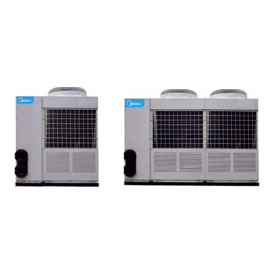
    MCAC-2008-11 Air-cooled Modular Chiller 2. Product Schedule dimension Net weight Model Refrigerant Power supply (L×W×H) (unit: mm) (kg) MGA-F30W/SN1 R410A 1514×850×1820 380-415V/3ph/50Hz MGA-F65W/SN1 R410A 2492×850×1820 380-415V/3ph/50Hz MGA-D30W/SN1 R410A 1514×850×1820 380-415V/3ph/50Hz MGA-D65W/SN1 R410A 2492×850×1820 380-415V/3ph/50Hz External appearance: 30 kW module 65kW module...
  • Page 4: Features

    MCAC-2008-11 Air-cooled Modular Chiller 3. Features Environmental-friendly refrigerant R410A will not destroy the ozonosphere. Modular design, flexible combination, more convenient for design and installation. The maximum combination of the system consists of 1 main unit and 7 slave units (for 30kW unit, 15 slave units, so maximum capacity can reach 520kW).
  • Page 5 MCAC-2008-11 Air-cooled Modular Chiller Easy connection between main unit and slave units. Connecting all the units together with a wired controller in series type. Using two-core shielded twisted wire as communication signal wire. Any of unit can be set as main unit by setting its address No.0, the other as slave units. Strong micro-computer intelligent control and monitor function.
  • Page 6: Specification

    MCAC-2008-11 Air-cooled Modular Chiller 4. Specification For fix speed heat pump 30kW module: MGA-F( )W/SN1 Model Combination (Main module + auxiliary module) Pieces Cooling Capacity Heating Capacity Power supply V/Ph/Hz 380-415/3/50 Type Scroll (fixed speed) Compressor Quantities Pieces Cooling Power input Heating 19.5 29.3...
  • Page 7 MCAC-2008-11 Air-cooled Modular Chiller For fix speed heat pump 30kW module: MGA-F( )W/SN1 Model Combination (Main module + auxiliary Pieces 1+10 1+11 1+12 1+13 1+14 1+15 module) Cooling Capacity Heating Capacity Power supply V/Ph/Hz 380-415/3/50 Type Scroll (fixed speed) Compressor Quantities Pieces Cooling...
  • Page 8 MCAC-2008-11 Air-cooled Modular Chiller For fix speed heat pump 65kW module: MGA-F( )W/SN1 Model Combination (Main module + auxiliary Pieces module) Cooling Capacity Heating Capacity Power supply V/Ph/Hz 380/3/50 Type Scroll (fixed speed) Compressor Quantities Pieces Cooling 21.5 64.5 107.5 150.5 Power input Heating...
  • Page 9 MCAC-2008-11 Air-cooled Modular Chiller For digital scroll heat pump 30kW module: MGA-D( )W/SN1 Model Combination (Main module + auxiliary module) Pieces Cooling Capacity Heating Capacity Power supply V/Ph/Hz 380-415/3/50 Type Scroll (1 digital scroll plus 1 fixed speed) Compressor Quantities Pieces Cooling Power input...
  • Page 10 MCAC-2008-11 Air-cooled Modular Chiller For digital scroll heat pump 30kW module: MGA-F( )W/SN1 Model Combination (Main module + auxiliary module) Pieces 1+10 1+11 1+12 1+13 1+14 1+15 Cooling Capacity Heating Capacity Power supply V/Ph/Hz 380-415/3/50 Type Scroll (1 digital scroll plus 1 fixed speed) Compressor Quantities Pieces...
  • Page 11 MCAC-2008-11 Air-cooled Modular Chiller For digital scroll heat pump 65kW module: MGA-D( )W/SN1 Model Combination (Main module + auxiliary Pieces module) Cooling Capacity Heating Capacity Power supply V/Ph/Hz 380/3/50 Type Scroll (1 digital scroll plus 3 fixed speed) Compressor Quantities Pieces Cooling 21.5...
  • Page 12: Dimension

    MCAC-2008-11 Air-cooled Modular Chiller 5. Dimension 5.1 30kW modular outline: 5.2 65kW modular outline:...
  • Page 13: Piping Diagrams & Pipe Connection Drawing

    MCAC-2008-11 Air-cooled Modular Chiller 6. Piping Diagrams & Pipe Connection Drawing 6.1 Refrigeration system sketch drawing for 30kW module unit 30kW module has two separate refrigeration systems (system A and system B), each system consists of one compressor and the two systems share one double-system plate exchanger. Condenser Four-way valve Filter...
  • Page 14 MCAC-2008-11 Air-cooled Modular Chiller 6.4 Water pipe sketch drawing for 65kW module unit system: 6.5 Sketch drawing of units combination system(30kW、65kW) Module unit can be combined by single unit, double units or both. By connecting each own inlet & outlet pipeline in series, 1-8 modules (2-16 units) can be combined and the max.
  • Page 15 MCAC-2008-11 Air-cooled Modular Chiller 6.6 Sketch drawing of auxiliary electric heater installation Water heater/chiller unit Gate valve 2 Back flush valve Gate valve 3 Temperature-testing tube Filter Pressure gauge Flow switch Drain valve Exhaust valve Absorbing pipe fittings Safety valve Gate valve Foundation Gate valve 1...
  • Page 16: Wiring Diagrams

    MCAC-2008-11 Air-cooled Modular Chiller 7. Wiring Diagrams 7.1 Outdoor wiring diagram: MGA-F(D)30W/SN1 & MGA-F(D)65W/SN1 module for main unit...
  • Page 17 MCAC-2008-11 Air-cooled Modular Chiller 7.2 Outdoor wiring diagram: MGA-F(D)30W/SN1 & MGA-F(D)65W/SN1 module for auxiliary unit...
  • Page 18: Electric Characteristics

    MCAC-2008-11 Air-cooled Modular Chiller 8. Electric Characteristics Outdoor Unit Power Supply Compressor Model Voltage Min. Max. TOCA MGA-F30W/SN1 19.9 74×2 11.8×2 0.67 MGA-F65W/SN1 42.9 74×4 11.8×4 0.67×2 3.1×2 MGA-D30W/SN1 19.9 74/82.4 11.8/12.7 0.67 MGA-D65W/SN1 42.9 (74/82.4) ×2 (11.812.7) ×2 0.67×2 3.1×2...
  • Page 19: Capacity Tables

    MCAC-2008-11 Air-cooled Modular Chiller 9. Capacity Tables 9.1 Cooling: MGA-F30W/SN1 MGA-D30W/SN1 Condensed water outlet temp. ( ) ℃ Difference of water Ambient temp. inlet and outlet temp. Capacity Water flow Power Capacity Water flow Power Capacity Water flow Power Capacity...
  • Page 20 MCAC-2008-11 Air-cooled Modular Chiller MGA-F65W/SN1 MGA-D65W/SN1 Condensed water outlet temp. ( ) ℃ Difference of water Ambient temp. inlet and outlet temp. Capacity Water flow Power Capacity Water flow Power Capacity Water flow Power Capacity Water flow Power ℃ ℃ 19.4 20.6 21.4...
  • Page 21 MCAC-2008-11 Air-cooled Modular Chiller 9.2 Heating: MGA-F30W/SN1 MGA-D30W/SN1 Difference Warm water outlet temp. ( ) ℃ of water Ambient inlet and temp. Water Water Water Water Water outlet Capacity Power Capacity Power Capacity Power Capacity Power Capacity Power flow flow...
  • Page 22 MCAC-2008-11 Air-cooled Modular Chiller MGA-F65W/SN1 MGA-D65W/SN1 Difference Warm water outlet temp. ( ) ℃ of water Ambient inlet and temp. Water Water Water Water Water outlet Capacity Power Capacity Power Capacity Power Capacity Power Capacity Power flow flow flow flow flow temp.
  • Page 23: Exploded View

    MCAC-2008-11 Air-cooled Modular Chiller 10. Exploded View 10.1 MGA-F30W/SN1...
  • Page 24 MCAC-2008-11 Air-cooled Modular Chiller Part Name Quantity Part Name Quantity Top cover Base ass'y Axial flow fan Suction pipe ass'y A Motor 31.1 Pressure controller Top cover Suction pipe ass'y B Motor bracket 32.1 Pressure controller Rear cover Accumulator cylinder Side board Middle partition plate Side sealed board...
  • Page 25 MCAC-2008-11 Air-cooled Modular Chiller 10.2 MGA-F65W/SN1...
  • Page 26 MCAC-2008-11 Air-cooled Modular Chiller Part Name Quantity Part Name Quantity Top cover Base ass'y Axial flow fan Strengthen bracket Motor Compressor Beam Accumulator cylinder Suction pipe ass'y B Base bracket Pressure controller Base bracket Suction pipe ass'y A Clamp Pressure controller Holder for Plate Heat-exchanger 4-way valve ass'y E-part box ass'y...
  • Page 27 MCAC-2008-11 Air-cooled Modular Chiller 10.3 MGA-D30W/SN1...
  • Page 28 MCAC-2008-11 Air-cooled Modular Chiller Part Name Quantity Part Name Quantity Top cover 31.1 Pressure controller Axial flow fan Suction pipe ass'y D Motor 32.1 Pressure controller Top cover Accumulator cylinder Motor bracket Middle partition plate Rear cover Compressor Side board Compressor Side sealed board Clapboard supporting board...
  • Page 29 MCAC-2008-11 Air-cooled Modular Chiller 10.4 MGA-D65W/SN1 Part Name Quantity Part Name Quantity Top cover Accumulator cylinder Axial flow fan Base bracket Motor Base bracket Beam Clamp Suction pipe ass'y B Holder for Plate Heat-exchanger Pressure controller E-part box ass'y Suction pipe ass'y A 36.1 Compressor capacitor Pressure controller...
  • Page 30 MCAC-2008-11 Air-cooled Modular Chiller 4-way valve ass'y 36.11 Wire joint, 4p Muffler Bracket ass'y 4-way valve Base ass'y Pipe joint Bracket ass'y Strainer Drainage pan holder Pressure controller Connecting pipe ass'y EEV solenoid Connecting pipe Discharge temp sensor 4-way valve connection pipe Suction pipe ass'y D Heat-exchanger plate Pressure controller...
  • Page 31: Troubleshooting

    MCAC-2008-11 Air-cooled Modular Chiller 11. Troubleshooting 11.1 Failure & Protection Codes of the Module Code Trouble Water-flow check trouble(wire controller and control board must be restarted when the trouble is displayed for the third time) Power phases sequence failure Communication failure Total outlet water Temperature sensor failure (available for main unit) Plate heat exchanger outlet water Temperature sensor failure Condenser A tube Temperature sensor failure...
  • Page 32 MCAC-2008-11 Air-cooled Modular Chiller Refrigerant over-charged Discharge the additional refrigerant High surrounding Temp Measure the surrounding Temp Surrounding Temp. is lower Measure the surrounding Temp Low discharge pressure Refrigerant leak or insufficient Leak-hunting or recharging (Cooling) Low suction pressure Refer to the “low suction pressure” Refrigerant over-charged Discharge the additional refrigerant High suction pressure...
  • Page 33 MCAC-2008-11 Air-cooled Modular Chiller Low suction pressure Refer to “low suction pressure” part. Adjust the refrigerant volume, check Compressor liquid pumping caused by Abnormal noise caused expansion valve suction the entrance of liquid refrigerant. compressor degree of superheat. Compressor aging Replace compressor Panel bolt loosed Fix all components...
  • Page 34: Installation

    MCAC-2008-11 Air-cooled Modular Chiller 12. Installation 12.1 Unit Installation 12.1.1 Transportation Be sure that the package will be transported safely, unpack until reach installation site. The leaning angle during the transportation should be smaller than 15 degree to prevent the module from rolling over.
  • Page 35 MCAC-2008-11 Air-cooled Modular Chiller 12.1.2 Required installation place Clean, bright and well ventilated place such as roof, balcony or courtyard. Place without the interference of lampblack, steam and other kind of heat source. Place where it is convenient for piping and water drainage with the least influence to surroundings caused by noise, cool or heat wind.
  • Page 36 MCAC-2008-11 Air-cooled Modular Chiller 12.1.4 Operation Limits a. The range of voltage: Power supply: 380V 3ph 50Hz, the permitted max. Voltage: 418V, the permitted min. voltage: 342V. b. Temperature range for unit operation: Item Cooling mode Heating mode Ambient temperature Chilled water outlet Ambient temperature Heating water outlet...
  • Page 37 MCAC-2008-11 Air-cooled Modular Chiller 12.2 Water System Installation Every pipeline’s joint has outlet and inlet mark. Please notice when connecting pipelines: Because the plate heat-exchanger has been used, the space for water passing is narrow, so it is easy to be jammed by particulate, which may cause harmful freezing and damage the system. So it is strongly recommended to install a 20-item mesh net Y-shaped filter close to module-side chilled-water inlet (or cooling water) as much as possible.
  • Page 38 MCAC-2008-11 Air-cooled Modular Chiller Reference figure of water system installation...
  • Page 39 MCAC-2008-11 Air-cooled Modular Chiller Water tank kW is the unit for cooling capacity and L is the unit for G water flow in the formula counting the minimum water flow. Comfortable type air conditioner G= cooling capacity×2.6L Process cooling application conditioner G= cooling capacity×7.4L If the total water volume in the system is less than the required minimum volume, the additional water tank is necessary in order to avoid the compressor On and Off frequently.
  • Page 40 MCAC-2008-11 Air-cooled Modular Chiller Water Quality The demanded quality of the water used by system is shown as follows: The freezing point and the boiling point of the glycol liquor(The consistency of glycol for preventing freezing) Liquor poidometer Consistency% volumenometer 13.6 18.1 22.9...
  • Page 41 MCAC-2008-11 Air-cooled Modular Chiller Water flow switch installation reference 1. Water flow flake selecting Selecting flow flake should be according to the diameter of the water pipe at where the water switch installed. The length of flow flake should be a little short than the water pipe diameter. It cannot be too short, otherwise its action will be difficult when it gets the water current shocking.
  • Page 42 MCAC-2008-11 Air-cooled Modular Chiller Reference figure of multi modules connection A type: B type:...
  • Page 43 MCAC-2008-11 Air-cooled Modular Chiller 12.3 Wiring Installation All wiring installation should be done by qualified person. 12.3.1 Precautions: 1. The power supply must be stable when the unit is running. Considering all voltage-drop factors, the running voltage needed by the system should be kept within ±10% range of the rating. Too high or too low voltage will have bad effect on the unit.
  • Page 44 MCAC-2008-11 Air-cooled Modular Chiller Cooper core, PVC insulation, PVC jacket, electric power cable ZR-VV Anti-burning, Cooper core, PVC insulation, PVC jacket, electric power cable Heavy-duty, rubber-bushed, soft electric power cable 2. Specification of control wiring Length (m) Specification Description Communication signal wiring KVVP-300/300 2×1.0mm ≤500m Wiring controller signal wiring...
  • Page 45 MCAC-2008-11 Air-cooled Modular Chiller 300 or 120×2 300 or 150×2 400 or 150×2 400 or 150×2 400 or 150×2 The diameter selections of these preceding cables refer to allowable carrying capacity when Remark: no-armored cables 0.6/1KV PVC with three or four-cores, insulation and PVC jacket lay the continuous charge in air.
  • Page 46 MCAC-2008-11 Air-cooled Modular Chiller 1-1/4 1-1/2 2-1/2 1125 Water flow switch can be installed outdoors without waterproof and horizontally or vertically. The Note: buffer pipes must be installed in front of and behind water flow switch and its length should be 5 times of pipe diameter;...
  • Page 47 MCAC-2008-11 Air-cooled Modular Chiller 9. The module wiring and the installation wiring refer to the following:...
  • Page 48 MCAC-2008-11 Air-cooled Modular Chiller Unit electric control & communication figure (for 30kW module)
  • Page 49 MCAC-2008-11 Air-cooled Modular Chiller Unit electric control & communication figure (for 65kW module)
  • Page 50 MCAC-2008-11 Air-cooled Modular Chiller Note: Electrify unit 12 hours before starting to pre-heating the compressors, if it is not been done in advance, the compressor may be damaged. Regulate the water flow switch and the valve on the inlet pipeline carefully to ensure the water flow can keep the 90% of the rating.
  • Page 51 MCAC-2008-11 Air-cooled Modular Chiller “00” presents to select digital compressor (as the main unit.) “11” presents to select constant compressor (as the auxiliary unit.) Notice: a. The DIGIT switch has been set well in the factory and needn’t change. b. Please turn on the main power 12 hours before staring to preheat the compressor. If the compressor is not preheated enough, it maybe damaged.
  • Page 52 MCAC-2008-11 Air-cooled Modular Chiller Controlled by micro- controller When the Temp. is lower than 125 , compressor will not work. When ℃ Temp Sensor inside digital the Temp. is higher than 125 , the capacity output of digital ℃ compressor compressor will decrease to 40%.
  • Page 53: Maintenance

    4. Tighten all the wire connections. Accessory replacement Only MIDEA accessory can be used and please don’t use any different one. Refrigeration system Check the discharge and suction pressure to determine whether the unit needs to recharge or not. Take leakage test for the system;...
  • Page 54 MCAC-2008-11 Air-cooled Modular Chiller In this case, leakage test must be done by using nitrogen (15~20 kgf/cm ) or refrigerant. If necessary, welding should be done after all gas of the system is discharged out. 1) Connect the vacuum pump pipeline to the refrigerant charging hole. 2) Vacuum refrigerant pipeline more than 15 minutes and confirm it achieve -1.0×10⁵Pa (-76cmHg).
  • Page 55 MCAC-2008-11 Air-cooled Modular Chiller 15. Control System 15.1 PCB Outline and Description 15.1.1 PCB, outlook view (30kW & 65kW module) Notice: 1. Failure When main unit fails, the unit stops as well as the others stop too. When auxiliary unit fails, this unit stops while the others keep running. 2.
  • Page 56 MCAC-2008-11 Air-cooled Modular Chiller : Condenser B tube Temperature sensor (failure code E6, protection code P7). : Condenser A tube Temperature sensor (failure code E5, protection code P6). If any one system needs to start the outdoor fan, the fan will be started by the unit electric controller. The fan has two speed levels: high and low which all depends on the T4 Temperature.
  • Page 57 MCAC-2008-11 Air-cooled Modular Chiller “11” presents selecting constant compressor (as the auxiliary unit). 9——ADDRESS 0 presents NO. 0 main unit 1~F presents NO 1~15 auxiliary units respectively For modular units, each module unit has same electrical control function, while the unit can be set as main unit or auxiliary unit by adjust the address switch of the PCB.
  • Page 58 MCAC-2008-11 Air-cooled Modular Chiller for 10 minutes. If DLT is lower than 125 , protection will eliminate, on the other hand, if DLT keeps ℃ ℃ increasing to 140 or more, it enter red area when the compressor stop and restart 3 minutes later if the ℃...
  • Page 59 MCAC-2008-11 Air-cooled Modular Chiller checked at the beginning of electrifying. During the running, they will not be detected. 27——Transformer output 28——“ON/OFF” port 15.2 Failure & Protection Codes of the Module Code Trouble Water-flow check trouble (wire controller and control board must be restarted when the trouble is displayed for the third time) Power phases sequence failure Communication failure...
  • Page 60 MCAC-2008-11 Air-cooled Modular Chiller 15.3 Controllers 15.3.1 Wired Controller: KJR-08B/BE: Name of keys on the wired controller and the keypad operation description: 1. ON/OFF button: In the power off status, press this key and the startup indicator comes on, and the wire controller enters the startup status and keeps the current set information such as temperature value, timing.
  • Page 61 MCAC-2008-11 Air-cooled Modular Chiller keep idle without adjustment operation within 8 seconds after entering the timing setup status, the system will confirm the time setup and exit the timing setup status. Press [TIME OFF] key, as per the above method to set close time.
  • Page 62 MCAC-2008-11 Air-cooled Modular Chiller Name and function description of LCD screen of wired controller Installation procedure: 1. The wiring procedure and principles are shown in the figure: Note: Use PQE position connects with each other when several wire-controllers are parallel. 2.
  • Page 63 MCAC-2008-11 Air-cooled Modular Chiller Operation procedure of wired controller: 1. Press AUTO/MANUAL mode at shutdown status, you could select MANUAL or AUTO turn-on mode as you want. The function is invalid at startup status. In Manual mode, press [PAGEUP/TEMP+] or [PAGEDOWN/TEMP-] button for select your require online unit quantity.
  • Page 64 MCAC-2008-11 Air-cooled Modular Chiller ●Operation procedure of units information querying 1. Press [QUERY] entering Check status. 2. Press [ADDRESS+] or [ADDRESS-] button, select the unit you are wanted to query. 3. Press [PAGEUP/TEMP+)] or [PAGEDOWN/TEMP-] button to query the units information, which includes outdoor ambient temperature T4, pipe temperature T3, setting temperature Ts, CEB out water temp.
  • Page 65 MCAC-2008-11 Air-cooled Modular Chiller 15.3.2 CCM10 LCD Touch Screen (optional) It can control 8 units, 16 compressors. Control function as Query/Mode setting/Lock/Weekly timer setting/Power failure memory. Mechanical installation LCD touch screen normally installed in the casing of unit or the front board of console. Before installation, you should drill a mounting hole at unit casing or the front board of console firstly;...
  • Page 66 MCAC-2008-11 Air-cooled Modular Chiller Fix LCD at fore panel from rear side of the panel by screw driver. You must insure that the installing site of gasket is correct; torque is 0.5Nm or less, if not, screen would be damaged. Electrical installation LCD electrical interface composed by a power supply interface and three Serial Communications ports.
  • Page 67 MCAC-2008-11 Air-cooled Modular Chiller of main modular unit; connect the 5 foot to “E ” communication port of main modular unit; and connect the 3 foot to “Q ” communication port of main modular unit. Wiring illustration as above. Operation Description of LCD Touch Screen The base conditions for using this LCD: 1) Voltage range: Input voltage: 24VDC±2%;...
  • Page 68 MCAC-2008-11 Air-cooled Modular Chiller Query window Click “query”, access to the following window: In this page, you can query the information from unit No.0 to No.15. On-line units’ number shows in light blue, while out-line units' number shows in gray. Page 1 of Query Window: Press a certain on-line units' number, the following window shows and relevant parameters of the units system could be queried.
  • Page 69 MCAC-2008-11 Air-cooled Modular Chiller At this page, you could select Operation Mode and Control Mode, adjust temperature and set Power Failure Memory. Temperature setting range: Cooling 7 ~12 , Heating 45 ~50 . ℃ ℃ ℃ ℃ Malfunction queried window: Press “Check Error”...
  • Page 70 MCAC-2008-11 Air-cooled Modular Chiller In this window, there are seven timing segments from “Time_set1” to “Time_set 7” for your setting. Click a timing segment, and then click “Setting”, enter to this time parameter setting, window as follows: Electricity control function description LCD operation description Query function Click “Query”...
  • Page 71 MCAC-2008-11 Air-cooled Modular Chiller Under cooling mode operation, click temperature decreasing key to decrease temperature, once a degree, default temperature is 7 . ℃ Cooling adjusted temperature range is 7 ~12 ℃ ℃ Under heating mode operation, click temperature increasing key to increase temperature, once a degree, default temperature is 45 .
  • Page 72 MCAC-2008-11 Air-cooled Modular Chiller Operation mode and control mode setting Select “Mode Setting” window by the key in principal window, and then select “Run Way” and required “Run Unit” quantity in the mode setting window. When “Auto” control mode is selected, operation mode and control mode in there are stand for the modes of whole unit group system, thus you don't need to selected the”...

This manual is also suitable for:

Mga-f65w/sn1Mga-d30w/sn1Mga-d65w/sn1

Table of Contents