
Related Manuals for Midea MCCH30A-TA3SL


Summary of Contents for Midea MCCH30A-TA3SL
- Page 1 Библиотека СОК DM13-01.01.14en AIR-COOLED SCROLL MODULAR CHILLER TECHNICAL SERVICE MANUAL R410A (30kW-250kW) 50Hz Models: MCC(D)H30A-TA3SL MCC(D)H65A-SA3L MCCH130A-SA3L MCCH185A-SA3 MCCH250A-SA3T...
-
Page 2: Table Of Contents
Air-cooled modular chiller unit Content 1 General information ................3 2. Features ....................5 3. Specification ...................9 4 Dimension ....................17 5 Refrigeration system drawing ..............27 6. Piping diagram ..................30 7 Wiring diagrams..................36 8 Electric characteristics .................50 9 Capacity tables ..................51 10 Troubleshooting ................. -
Page 3: General Information
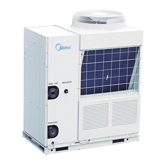
Constant speed. System type Modular chiller. Midea 1.2 Product schedule Heat Maximum Maximum Model Power supply Wired controller exchanger type combinations capacity(kW) MCCH30A-TA3SL 380~ 415V/3ph/50Hz Double pipe KJR-120A/MBE MCDH30A-TA3SL 380~415V/3ph/50Hz Double pipe KJR-120A/MBE 1040 KJR-120A/MBE MCCH65A-SA3L 380~400V/3ph/50Hz Shell and tube MCCD65A-SA3L... - Page 4 Air-cooled modular chiller unit 1.3 External appearance: MCCH65A-SA3L MCCH30A-TA3SL MCCD65A-SA3L MCDH30A-TA3SL MCCH185A-SA3 MCCH130A-SA3L MCCH250A-SA3T...
-
Page 5: Features
Air-cooled modular chiller unit 2. Features 1). Low ambient temperature cooling function (Available for MCC(D)H30A-TA3SL, MCC(D)H65A-SA3L, MCCH130A-SA3L) The ambient temperature is down to -10℃ in cooling mode, and heating down to -10˚C ambient by added one board (see picture1). Wide ambient temperature range are available by adjustable address between different conditions to meet different requirements. - Page 6 Air-cooled modular chiller unit 50Hz MCAC-ATSM-2012-10 4).Humanized remote control (For the module with KJR-120A/MBE) S7 address on PCB should be switched to ON to realize remote control, which including remote ON/OFF, remote heating and cooling mode selection, remote alarm. The customer can simply and conveniently control the chiller and acquire the running information on real time in door.
- Page 7 Air-cooled modular chiller unit Water outlet temp. Water outlet temp. Water outlet temp. Total water outlet temp. Total water outlet temp. Total water outlet temp. (Just for master unit) (Just for master unit) (Just for master unit) Three-core shielding Three-core shielding twisted pair twisted pair Wired controller...
- Page 8 Air-cooled modular chiller unit 50Hz MCAC-ATSM-2012-10 12).Strong micro-computer intelligent control and monitor function Optimizing the design of system and using varieties of protection devices, to make the system more safe and reliable. 13). Superior reliability System will be more reliable with new type efficient heat exchanger. Evaporator 30kW module adopts double pipe heat exchanger ,...
-
Page 9: Specification
Air-cooled modular chiller unit 3. Specification Model MCCH30A-TA3SL MCDH30A-TA3SL Cooling Capacity Btu/h 102,300 102,300 Heating Capacity Power supply V/Ph/Hz 380-415/3/50 Manual switch Power supply Fuse Type Fixed speed Digital Scroll + Fixed speed Quantity Pieces ZPD67KCE-TFD-532/ Model ZP67KCE-TFD-522 ZP67KCE-TFD-522 Brand... - Page 10 Air-cooled modular chiller unit 1) Protection for over-high discharge pressure. 2) Protection for over-low suction pressure. 3) Power supply phase sequence protection. 4) Anti-freezing protection in cooling mode. 5) Anti-freezing protection in Winter. 6) Protection for compressor over current. 7) Protection for compressor overload. 8) Outlet and inlet water temperature difference Safety protection device protection.
- Page 11 Air-cooled modular chiller unit Model MCCH65A-SA3L MCDH65A-SA3L Cooling Capacity Heating Capacity Cooling 20.4 20.4 Cooling rated current 36.5 36.5 Power input Heating 21.5 21.5 Heating rated current 37.2 37.2 Power supply V/Ph/Hz 380-400/3/50 380-415/3/50 Manual switch Power supply Fuse Max. Input consumption 27.9 27.1 Max.
- Page 12 Air-cooled modular chiller unit 1) Protection for over-high discharge pressure. 2) Protection for over-low suction pressure. 3) Power supply phase sequence protection. 4) Anti-freezing protection in cooling mode. 5) Anti-freezing protection in Winter. 6) Protection for compressor over current. 7) Protection for compressor overload. Safety protection device 8) Outlet and inlet water temperature difference protection.
- Page 13 Air-cooled modular chiller unit 50Hz Model MCCH130A-SA3L Cooling Capacity Btu/h 443,560 Heating Capacity Power supply V/Ph/Hz 380-400/3/50 Manual switch Power supply Fuse Type Fixed speed Scroll Quantity Pieces Model SH140A4ALC Compressor Brand Danfoss Capacity 34.7×4 Input 10860×4 Rate current(RLA) 21.4×4 Locked rotor Amp(LRA) 147×4 Cooling...
- Page 14 Air-cooled modular chiller unit Net weight 1150 Weight Operation weight 1270 Power wire ×No. 35×3+16×2 Signal wire ×No. 0.75x3-core Control type Wired controller 1) Protection for over-high discharge pressure. 2) Protection for over-low suction pressure. 3) Power supply phase sequence protection. 4) Anti-freezing protection in cooling mode.
- Page 15 Air-cooled modular chiller unit Model MCCH185A-SA3 MCCH250A-SA3T Cooling Capacity Btu/h 631,220 830,000 Heating Capacity Power supply V/Ph/Hz 380-400/3/50 380-400/3/50 Manual switch Power supply Fuse Type Scroll (fixed speed) Scroll (fixed speed) Quantity Pieces Model SH140A4ALC SH120A4ALC Brand Danfoss Danfoss Compressor Capacity 34.7×6 111231...
- Page 16 Air-cooled modular chiller unit 1) Protection for over-high Protection over-high discharge pressure. discharge pressure. 2) Protection for over-low suction 2) Protection for over-low suction pressure. pressure. 3) Power supply phase Power supply phase sequence protection. sequence protection. 4) Anti-freezing protection in 4) Anti-freezing protection in cooling mode.
-
Page 17: Dimension
Air-cooled modular chiller unit 4 Dimension 30kW module Front view Left view Top view... - Page 18 Air-cooled modular chiller unit Make-up NAME Air inlet Air outlet Water inlet Water outlet Drain water inlet...
- Page 19 Air-cooled modular chiller unit 65kW module Front view Top view Unit Model 2000 1880 1420 1500 MCC(D)H65A-SA3L inch 78.74 35.4 13.78 55.91 8.86 59.06 19.92 20.87 36.61 17.72...
- Page 20 Air-cooled modular chiller unit Name Top cover Air outlet Air inlet Water outlet Compressor Electric control box Water inlet...
- Page 21 Air-cooled modular chiller unit 130kW module Front view Side view Top view Anchor hole Unit Model 2000 1685 2080 1420 1550 1586 MCCH130A-SA3L inch 78.74 66.34 81.89 13.78 55.91 19.92 61.02 62.44...
- Page 22 Air-cooled modular chiller unit Name Top cover Condenser Compressor Evaporator Electric control box Air inlet Water outlet Water inlet Compressor...
- Page 23 Air-cooled modular chiller unit 185 kW module Model unit 2850 2000 2110 3470 2156 1888 2388 MCCH185A-SA3 inch 112.2 78.74 83.07 136.61 84.88 19.92 74.33 94.02...
- Page 24 Air-cooled modular chiller unit Name Top cover Compressor Evaporator Water outlet Electric control box Water inlet Condenser...
- Page 25 Air-cooled modular chiller unit 250kW module Front view Left view Hole for anchor boltΦ15 Bottom view Model unit 3800 2000 2130 1235 2156 1888 1551 MCCH250A-SA3T inch 149.6 78.74 83.86 48.62 84.88 22.56 74.33 61.06...
- Page 26 Air-cooled modular chiller unit Air outlet Air outlet Air outlet Air outlet Air inlet Name Top cover Compressor Evaporator Water outlet Electric control box Water inlet Condenser Transportation guard plate (Be removed off after installation)
-
Page 27: Refrigeration System Drawing
Air-cooled modular chiller unit 5 Refrigeration system drawing 5.1 30kW module refrigeration system sketch drawing Each module has two compressors with one separate unit, one double-pipe evaporator for two refrigerant systems. 4-way valve A Condenser 4-way valve B Compressor A Compressor B Water outlet Water inlet... - Page 28 Air-cooled modular chiller unit 65kW digital module (MCCD65A-SA3L) Each module has three compressors with one separate unit, one shell and tube evaporator for two refrigerant systems. Pressure switch low pressure cylinder B Compressor B 4-Way valve B Pressure switch Discharge switch Fan B Fan A Water flow direction...
- Page 29 Air-cooled modular chiller unit 5.4 185 kW module refrigeration system sketch drawing Each module has six compressors with three separate units, one shell and tube evaporator for six refrigerant systems. low pressure cylinder B Unit 2 4-Way valve B 3" Compressor B Fan B Fan A...
-
Page 30: Piping Diagram
Air-cooled modular chiller unit 6. Piping diagram 6.1 30kW module water pipeline sketch drawing The table below describes the symbols. Symbol Symbol explanation Symbol Symbol explanation Stop valve Y-shaped filter Pressure gauge Thermometer Water flow switch Circulating pump Gate valve Check valve Flexible joint Automatic discharge valve... - Page 31 Air-cooled modular chiller unit 30kW module water pipeline sketch drawing The table below describes the symbols. Symbol Symbol explanation Symbol Symbol explanation Safety valve Y-shaped filter Pressure gauge Thermometer Water flow switch Water pump Cut off valve Expansion tank Manometer Water replenishing valve...
- Page 32 Air-cooled modular chiller unit 6.2 65kW module water pipeline sketch drawing Expansion tank Water replenishing Main unit Dirt discharge valve Differential pressure by-pass valve Drain valve Terminal Auxiliary electric heater Two-way valve Three-way valve The table below describes the symbols. Symbol Symbol explanation Symbol...
- Page 33 Air-cooled modular chiller unit 6.3 130kW module water pipeline sketch drawing The table below describes the symbols. Symbol Symbol explanation Symbol Symbol explanation Stop valve Y-shaped filter Pressure gauge Thermometer Water flow switch Circulating pump Gate valve Check valve Flexible joint Automatic discharge valve...
- Page 34 Air-cooled modular chiller unit 6.4 185 kW module water pipeline sketch drawing The table below describes the symbols. Symbol Symbol explanation Symbol Symbol explanation Stop valve Y-shaped filter Pressure gauge Thermometer Water flow switch Circulating pump Gate valve Check valve Flexible joint Automatic discharge valve...
- Page 35 Air-cooled modular chiller unit 6.5 250kW module water pipeline sketch drawing The table below describes the symbols. Symbol Symbol explanation Symbol Symbol explanation Stop valve Y-shaped filter Pressure gauge Thermometer Water flow switch Circulating pump Gate valve Check valve Flexible joint Automatic discharge valve...
-
Page 36: Wiring Diagrams
Air-cooled modular chiller unit 7 Wire Diagrams 7.1 Wiring diagrams 30kW module Only for MCCH30A-TA3SL, MCDH30A-TA3SL) - Page 37 Air-cooled modular chiller unit MCCH65A-SA3L...
- Page 38 Air-cooled modular chiller unit MCCD65A-SA3L...
- Page 39 Air-cooled modular chiller unit 130kW module...
- Page 40 Air-cooled modular chiller unit MCCH130A-SA3L...
- Page 41 Air-cooled modular chiller unit 185 kW module...
- Page 42 Air-cooled modular chiller unit 250 kW module...
- Page 43 Air-cooled modular chiller unit 7.2 Networking communication schematic of main unit and auxiliary unit 30kW module Only for MCCH30A-TA3SL , MCDH30A-TA3SL)
- Page 44 Air-cooled modular chiller unit 65kW module (Only for MCCH65A-SA3L)
- Page 45 Air-cooled modular chiller unit 65kW module (Only for MCCD65A-SA3L)
- Page 46 Air-cooled modular chiller unit 130 kW module...
- Page 47 Air-cooled modular chiller unit 130kW module (MCCH130A-SA3L)
- Page 48 Air-cooled modular chiller unit 200kW module...
- Page 49 Air-cooled modular chiller unit 250kW module...
-
Page 50: Electric Characteristics
Air-cooled modular chiller unit 8 Electric Characteristics Outdoor Unit Power Supply Compressor Model Voltage Min. Max. TOCA MCCH30A-TA3SL 380-415 25.3 74(×2) 11.8(×2) 0.55 MCDH30A-TA3SL 380-415 25.3 74(×2) 11.8(×2) 0.55 MCCH65A-SA3L 380-400 147(×2) 21.4(×2) 0.865(×2) 4.0(×2) MCDH65A-SA3L 380-415 118/74/82.4 17.8/9.1/9.8 0.865(×2) 4.0(×2) -
Page 51: Capacity Tables
Air-cooled modular chiller unit 9 Capacity Tables 9.1 MCC(D)H30A-TA3SL Cooling: Ambient temp.(℃) Chilled water 21.00 25.00 30.00 35.00 40.00 46.00 outlet temp. Capacity Power Capacity Power Capacity Power Capacity Power Capacity Power Capacity Power (℃) 5.00 33.59 8.81 31.63 9.08 29.84 9.36 28.20... - Page 52 Air-cooled modular chiller unit Heating: Ambient temp.(℃) Hot water outlet temp. Capacity Power Capacity Power Capacity Power Capacity Power Capacity Power Capacity Power Capacity Power (℃) 40.00 19.89 6.13 24.86 6.97 29.25 7.74 32.50 8.42 35.33 8.86 39.57 9.39 45.50 10.14 41.00 19.22...
- Page 53 Air-cooled modular chiller unit MCC(D)H65A-SA3L Cooling Ambient temp.(℃) Chilled water 21.00 25.00 30.00 35.00 40.00 46.00 outlet temp. Capacity Power Capacity Power Capacity Power Capacity Power Capacity Power Capacity Power (℃) 5.00 72.77 17.97 68.52 18.52 64.64 19.10 61.10 19.69 57.25 20.67 52.67...
- Page 54 Air-cooled modular chiller unit 50Hz Heating: Ambient temp.(℃) Hot water outlet temp. Capacity Power Capacity Power Capacity Power Capacity Power Capacity Power Capacity Power Capacity Power (℃) 40.00 42.89 13.45 53.61 15.29 63.07 16.99 70.08 18.46 76.17 19.43 85.31 20.60 98.11 22.25 41.00...
- Page 55 Air-cooled modular chiller unit 9.3. MCCH130A-SA3L Cooling: Ambient temp.(℃) Chilled water 21.00 25.00 30.00 35.00 40.00 46.00 outlet temp. Capacity Power Capacity Power Capacity Power Capacity Power Capacity Power Capacity Power (℃) 5.00 145.54 35.93 137.04 37.05 129.29 38.19 122.20 39.37 114.50 41.34...
- Page 56 Air-cooled modular chiller unit Heating: Ambient temp.(℃) Hot water outlet temp. Capacity Power Capacity Power Capacity Power Capacity Power Capacity Power Capacity Power Capacity Power (℃) 40.00 85.78 26.91 107.22 30.57 126.14 33.97 140.16 36.93 152.34 38.87 170.63 38.33 196.22 41.39 41.00 82.89...
- Page 57 Air-cooled modular chiller unit 9.4 MCCH185A-SA3 Cooling: Ambient temp.(℃) Chilled water outlet 21.00 25.00 30.00 35.00 40.00 46.00 temp. Capacity Power Capacity Power Capacity Power Capacity Power Capacity Power Capacity Power (℃) 5.00 207.12 55.49 195.03 57.20 183.99 58.97 173.90 60.80 162.94 63.83...
- Page 58 Air-cooled modular chiller unit Heating: Ambient temp.(℃) Hot water outlet temp. Capacity Power Capacity Power Capacity Power Capacity Power Capacity Power Capacity Power Capacity Power (℃) 40.00 124.31 38.17 155.39 43.37 182.81 48.19 203.13 52.38 220.79 55.14 247.28 58.45 284.38 63.12 41.00 120.14...
- Page 59 Air-cooled modular chiller unit 9.5 MCCH250A-SA3T Cooling: Ambient temp.(℃) Chilled water 21.00 25.00 30.00 35.00 40.00 46.00 52.00 outlet temp. Capacity Power Capacity Power Capacity Power Capacity Power Capacity Power Capacity Power Capacity Power (℃) 5.00 279.89 68.96 263.55 71.09 248.63 73.29 235.00...
- Page 60 Air-cooled modular chiller unit Heating Ambient temp.(℃) Hot water outlet -10.00 -6.00 temp. Capacity Power Capacity Power Capacity Power Capacity Power Capacity Power Capacity Power Capacity Power (℃) 39.00 167.82 50.06 209.78 56.88 246.80 63.20 274.22 68.70 298.07 72.31 333.83 76.65 383.91 82.78...
-
Page 61: Troubleshooting
Air-cooled modular chiller unit 10 Troubleshooting Failure & Protection Codes of the Module 30kW module For MCCH30A-TA3SL and MCDH30A-TA3SL only) No, Code Trouble Error of outdoor EEPROM Power phase sequence error Communication error Total outlet water temperature sensor error (Be valid for main unit) - Page 62 Air-cooled modular chiller unit 65kW module (For MCCH65A-SA3L, MCCD65A-SA3L) Code Trouble Error of outdoor EEPROM Power phase sequence error Communication error Total water outlet temperature sensor error (Be valid for main unit) Unit outlet water temperature sensor error Pipe temperature sensor error in condenser A Pipe temperature sensor error in condenser B Outdoor ambient temperature sensor error Output of the power protector error...
- Page 63 Air-cooled modular chiller unit 130kW module (MCCH130A-SA3L) Code Trouble Error of outdoor EEPROM Power phase sequence error Communication error Total water outlet temperature sensor error (Be valid for main unit) Unit outlet water temperature sensor error Pipe temperature sensor error in condenser A Pipe temperature sensor error in condenser B Outdoor ambient temperature sensor error Output of the power protector error...
- Page 64 Air-cooled modular chiller unit 185 kW module MCCH185A-SA3 Code Trouble No, Water flow detection error (The third time) Power phase sequence error Communication error Total water outlet temperature sensor error Outlet water temperature sensor error in shell and tube exchanger Pipe temperature sensor error in condenser A Pipe temperature sensor error in condenser B Outdoor ambient temperature sensor error...
- Page 65 Air-cooled modular chiller unit 250 kW module MCCH250A-SA3T No, Code Trouble Error of outdoor EEPROM Power phase sequence error Communication error Error of total outlet water temperature sensor(Be valid for main unit) Outlet water temperature sensor error in shell and tube exchanger Pipe temperature sensor error in condenser A Pipe temperature sensor error in condenser B Outdoor ambient temperature sensor error...
- Page 66 Air-cooled modular chiller unit 10.2 Troubles and Solutions Troubles Possible reasons Solutions Air or other non-condensing gas still in the Discharge gas from refrigerant charging inlet. system. Re-vacuum the system if necessary. Fins in the condenser are dirty or foreign Clean condenser fins.
- Page 67 Air-cooled modular chiller unit 50Hz Troubles Possible reasons Solutions Confirm voltage not higher or lower than the rated Over high or over low voltage. Compressor stops voltage 10%. because of integrate Over high air expelling pressure or excessive See “Over high air expelling pressure” and “excessive temperature sensor or air low air suction pressure.
- Page 68 Air-cooled modular chiller unit 10.3 Typical malfunction solutions 1) High pressure and discharged temperature protection High pressure discharged protection. analysis Discharge temperature High pressure protection. discharge temp. protection protection. malfunction. Blower stops rotating or rotates in Inspect fan motor and reversed direction in cooling mode, capacitor (1phase)
- Page 69 Air-cooled modular chiller unit Discharge temperature protection. Discharge temperature Replace discharge switch is broken or joint temperature switch, fixed is loose. joint. Refrigerant is too less. Detect leakage for all system, append refrigerant. Couldn‟t open the EXV. Replace the EXV or coil. Cause dirty The EXV, capillary and filter...
- Page 70 Air-cooled modular chiller unit 2) Current protection Current protection The fin of heat exchanger is dirty or aged in cooling mode, Clean heat exchanger. or the shell and tube scaled strong. The fan motor stopped running Check the fan motor, in cooling mode, reversal and capacitor (1 phase) or run slowly.
- Page 71 Air-cooled modular chiller unit 4) Inlet &outlet water temperature difference protection Inlet &outlet water temperature difference protection. Refer to the water flow Water flow is lower. malfunction to analysis. The outlet water temperature Replace temperature sensor or inlet water temperature sensor.
- Page 72 Air-cooled modular chiller unit 7) Power supply phase sequence malfunction Power supply phase sequence malfunction. Adjust connecting wire. Phase sequence error. Lack of phase. Check power supply. Replace phase lack Phase lack protector is broken. protector. PCB mistakes to alarm. Replace PCB.
- Page 73 Air-cooled modular chiller unit 9) Water flow detection malfunction Water flow detection malfunction Open the pump or change; Water pump didn‟t open or error. inspect the power supply or control circuit of pump. Open the valve. Didn‟t open the valve in system. Replace the water flow The water flow detection switch switch,...
- Page 74 Air-cooled modular chiller unit 10) Total outlet water temperature sensor malfunction Total outlet water temperature sensor malfunction The circuit of total outlet water Replace temperature sensor. temperature sensor is broken. The circuit of total outlet water Replace temperature temperature sensor is shorten. sensor.
- Page 75 Air-cooled modular chiller unit 12) The unit inlet water temperature sensor malfunction The unit inlet water temperature sensor malfunction The unit‟s circuit of inlet water Replace temperature sensor. temperature sensor is broken. The unit‟s circuit of inlet water Replace temperature sensor. temperature sensor is shorten.
- Page 76 Air-cooled modular chiller unit 14) Ambient temperature sensor malfunction Ambient temperature sensor malfunction. The circuit of ambient temperature Replace temperature sensor. sensor is broken. The circuit of ambient temperature Replace temperature sensor. sensor is shorten. The joint of ambient temperature Fixed joint.
-
Page 77: Installation
Air-cooled modular chiller unit 11 Installation 11.1 Unit Installation 11.1.1 Transportation The angle of inclination should not be more than 15º when carrying the unit, to avoid overturn of the unit. a. Rolling handling: several rolling rods of the same size are placed under the base of the unit, and the length of each rod must be more than the outer frame of the base and suitable for balancing of the unit. - Page 78 Air-cooled modular chiller unit 65kW module 130kW module...
- Page 79 Air-cooled modular chiller unit 185kW module The position should be provided with an at least 50mm thick wood block, cloth or hard paper, to avoid damages to the unit. The position should be provided with an at least 50mm thick wood block, cloth or hard paper, to avoid damages to the unit.
- Page 80 Air-cooled modular chiller unit 11.1.2 Installation space ● Requirements of arrangement space of the unit 1) To ensure adequate airflow entering the condenser, the influence of descending airflow caused by the high-rise buildings around upon the unit should be taken into account when installing the unit. 2) If the unit is installed where the flowing speed of air is high, such as on the exposed roof, the measures including sunk fence and Persian blinds can be taken, to prevent the turbulent flow from disturbing the air entering the unit.
- Page 81 Air-cooled modular chiller unit 130kW module 185kW module Input of airflow Input of airflow Input of airflow Input of airflow...
- Page 82 Air-cooled modular chiller unit 250kW module Input of airflow Input of airflow Input of airflow Input of airflow The recommend space parameter Installation space (mm) Module MCCH30A-TA3SL MCDH30A-TA3SL MCCH65A-SA3L ≥1500 ≥2000 ≥2000 ≥1500 ≥8000 MCDH65A-SA3L MCCH130A-SA3L MCCH185A-SA3 ≥2000 MCCH250A-SA3T ≥2000 Space requirements for parallel installation of multiple modular units.
- Page 83 Max unit combined Model L(mm) M(mm) N(mm) quantity ≥ ≥ ≥ MCCH30A-TA3SL ≥ ≥ ≥ MCDH30A-TA3SL ≥ ≥ ≥ MCCH65A-SA3L ≥ ≥...
- Page 84 Air-cooled modular chiller unit Location drawing of installation foundation of the unit (unit: mm) 30kW module 65kW module 130kWmodule 1550 D r a i n a g e c h a n n e l C o n c r e t e C e m e n t m o r t a r Drainage channel Anchor bolt...
- Page 85 250kW module 1551 1551 Drainage channel Concrete Cement mortar Drainage channel Hole for anchor bolt Schematic diagram o nstallation dimension of the unit Load distribution Unit: kg Model MCCH30A-TA3SL MCDH30A-TA3SL MCCH65A-SA3L MCDH65A-SA3L MCCH130A-SA3L MCCH185A-SA3 MCCH250A-SA3T 65KW 130KW 30KW 185 KW 250KW...
- Page 86 Air-cooled modular chiller unit 1 .4 Installation of damping devices ※ Damping devices must be provided between the unit and its foundation. By means of the Φ15mm diameter installation holes on the steel frame of the unit base, the unit can be fastened on the foundation through the spring damper.
- Page 87 Air-cooled modular chiller unit d. The pump installed in the water pipeline system should be equipped with starter. The pump will directly press water into the heat exchanger of the water system. e. The pipes and their ports must be independently supported but should not be supported on the unit. f.
- Page 88 Air-cooled modular chiller unit Performance adjustment factors The antifreeze must be required according to anyone condition as following: 1. The outlet water temperature is below 5 ℃ 2. The ambient temperature is below 0 ℃ 3. Don‟t start up the unit for a long time. 4.
- Page 89 Air-cooled modular chiller unit Foreign matter in the chilled water system will adversely affect the heat transfer capability of the evaporator, and could increase the pressure drop and reduce the water flow. To provide optimum unit operation, proper water treatment must be maintained. Refer to the able as following. Fouling Factor Fouling Factor Difference of water...
- Page 90 Air-cooled modular chiller unit d. Special grounding screws should be used for earth connection. Bolts should not be installed or removed at will; otherwise flow switches may suffer deformation and failure. e. Flow switches have been set at minimal flow value before leaving the factory. They should not be adjusted below the setting value at the factory, or they may suffer failure.
- Page 91 Air-cooled modular chiller unit 2) Installation mode II n :the module quantity, max 16 1 .2.5 Installation of water system pipeline for 65kW module Installation of single-module water system pipeline Installation of multi-module water system pipeline 1) Installation mode I (recommended installation mode) n :the module quantity, max 6...
- Page 92 Air-cooled modular chiller unit less than 6 modules 2) Installation mode III (recommended installation mode) n : the module quantity, max 16 Installation mode A: less than 16 modules 3) Installation mode IV n : the module quantity, max16...
- Page 93 Air-cooled modular chiller unit No.n module No.(n-1) module No.1 module No.(n-1) address No.(n-2) address No.0 address Drill dead hole at the position, and move the total effluent temperature sensor at No.0 address to the position Water flow switch No.(n-2) module No.(n-3) module No.2 module No.(n-3) address...
- Page 94 Air-cooled modular chiller unit Electric control box Total water outlet temp sensor Water intlet Water outlet Installation of multi-module water system pipeline 1) Installation mode I (recommended installation mode) n : the module quantity, max8 No.1 unit No.(n-1) unit No.n unit (n≤8) No.0 address(main unit) No.(2n-3) address No.(2n-1) address...
- Page 95 Air-cooled modular chiller unit Multi-module combination installation involves special design of the unit, so relevant explanation is given as follows. Installation mode of multi-module combination water system pipeline n : the module quantity, max5 a. Installation mode I (recommended installation mode) No.1 unit No.(n-1) unit No.n unit (n≤5)
- Page 96 Air-cooled modular chiller unit Less than 8 modules Notice: 1) For installation of multi-module, the most modules should be not more than 8 modular units. 2) For installation of multi-module, please drill a dead hole(Φ9mm) at the total water outlet pipeline, and move the total water effluent temperature sensor at No.0 address to the hole.
- Page 97 Air-cooled modular chiller unit Table of diameter parameters of main inlet and outlet pipes for 130kW module Total inlet and outlet water Total inlet and outlet water Unit model x quantity Unit model x quantity pipe diameter pipe diameter 130×1 DN65 130×5 DN125...
- Page 98 Air-cooled modular chiller unit 50Hz Minimum and Maximum water flow rates Item Water flow rate(m3/h) Model Minimum Maximum 4.68 5.72 4.68 5.72 10.08 12.32 10.08 12.32 18.54 22.66 27.9 34.1 38.7 47.3 1 .2.10 Design of the store tank in the system a.
- Page 99 Air-cooled modular chiller unit maximum allowable pressure and cause water to discharge from the pressure relief valve, thus wasting water. If the closed tank is too large, when the water temperature drops, the system pressure may decrease to a level below the minimum allowable value and cause trouble in the air vent. Therefore, accurate sizing of a closed expansion tank is essential.
- Page 100 Air-cooled modular chiller unit 1 .3.1 Precautions: 1. The air-conditioner should apply special power supply, whose voltage should conform to rated voltage. 2. Wiring construction must be conducted by the professional technicians according to the labeling on the circuit diagram. 3.
- Page 101 Air-cooled modular chiller unit ● Only use 380-415V 3Ph 50Hz rated power supply for the unit, and the maximum allowable range of voltage is 342V-418V. ● All electric wires must conform to local wiring connection norm. The suitable cables should be connected to power supply terminal through wiring connection holes at the bottom of the electric cabinet.
- Page 102 Air-cooled modular chiller unit 1 .3.4 Wiring steps Step Content Check the unit and ensure that it is connected with grounding wires correctly, to avoid leakage, and the grounding devices should be mounted in strict accordance with the requirements of electrical engineering rules. The grounding wires can prevent electric shock.
- Page 103 Air-cooled modular chiller unit Note: (For the module with KJR-120A/MBE) ○ 1 .Wiring of “ON/OFF” weak electric port Corresponding parallel connect the “ON/OFF” port of the main unit‟s electric control box, then, connect the “ON/OFF” signal (provide by user) to the “ON/OFF” port of main unit as follows. 0# electric control box “ON/OFF”...
-
Page 104: Commissioning
Air-cooled modular chiller unit 1 Commissioning 1. Preparation ● After the water system pipeline is flushed several times, please make sure that the purity of water meets the requirements; the system is re-filled with water and drained, and the pump is started up, then make sure that water flow and the pressure at the outlet meet the requirements. -
Page 105: Maintenance
Air-cooled modular chiller unit 1 Maintenance Maintenance for main components: ● Close attention should be paid to the discharge and suction pressure during the running process. Find out reasons and eliminate the failure if abnormality is found. ● Control and protect the equipment. See to it that no random adjustment be made on the set points on site. ●... - Page 106 Air-cooled modular chiller unit system is discharged. Before injecting refrigerant, the whole refrigeration system must be completely dry and of vacuum pumping. ● Connect vacuum pumping pipe at the fluoride nozzle at low-pressure side. ● Remove air from the system pipe with vacuum pump. The vacuum pumping lasts for above 3 hours. Confirm that the indication pressure in dial gauge is within the specified scope.
- Page 107 Air-cooled modular chiller unit Regularly preventive maintenance plan Maintenance Items Frequency Qualify Standards (Settlement) Note Judge whether there is abnormal sound by Noise Anytime Watch from one meter hearing; away from the center of Watch whether the swings of distribution pipes General Vibration Anytime...
- Page 108 Air-cooled modular chiller unit Maintenance Safety Requirement Each component should be maintained by qualified technicians. Please contact competent maintenance technicians in the event of leakage or breakdown. The safety devices should be checked after each maintenance. Once leakage occurs, all the refrigerant in unit should be pumped out and the leak point should be repaired and then charge the unit with suitable refrigerant according to the nameplate.
-
Page 109: Control System
Air-cooled modular chiller unit 1 Control System 1 .1 PCB Outline and Description 1 .1.3 New 30kW module PCB, outlook view (Available for 10 9 8 7 6 5 24 25 26 1 .1.4 New30kW module components description (Available for Detail information Detection of current of the compressor A1 (Protection code P4). - Page 110 Air-cooled modular chiller unit 3) T4, T3B and T3A: when the temperature sensor is detected to suffer open circuit or short circuit, fault alarm will occur. ● When the main unit suffer fault of temperature sensor: the main unit and subordinate units will be shut down. ●...
- Page 111 Air-cooled modular chiller unit 2) Subordinate unit: (Water flow detection will not be done). COM (I) 485 communication port (Fault code E2). COM (O) is interconnected with P, Q and E of COM (I), used for RS-485 communication. 1) If faults occur between the wired controller and the main unit module, all modules will be shut down. 2) If faults occur between the main unit and subordinate units, the subordinate unit module suffering communication fault will be shut down.
- Page 112 Air-cooled modular chiller unit Each modular part of modular unit has the same electric control function, and the main unit and subordinate units can be set through address code on the electric control board. The address code 0 # is provided as the main unit. The priority of being the main unit is given to the unit with digital compressor, and other addresses are subordinate units.
- Page 113 Air-cooled modular chiller unit outlook view: 10 9 7 6 13 5 14 1 2 4 MGBL-D65W/RN1 module components description: Detail information Detection of current of the compressor A1 (Protection code P4). Detection of current of the compressor B1 (Protection code P5). Current is not detected within the initial 5 seconds after the compressor is started up.
- Page 114 Air-cooled modular chiller unit Adjustment range of constant speed capability: ON and OFF. Adjustment range of constant speed capability: ON and OFF. Total outlet water temperature sensor (Fault code E3). Only the main unit is valid, and the subordinate units are invalid. Under refrigerating mode and heating mode, conduct adjustment according to the magnitude of total outlet water temperature.
- Page 115 Air-cooled modular chiller unit 2) If faults occur between the main unit and subordinate units, the subordinate unit module suffering communication fault will be shut down. Less units will be detected by the wired controller, which may display EA, and in the meanwhile, the indicator lamp of the wired controller will flash, restart 3 minutes later after malfunction be removed.
- Page 116 Air-cooled modular chiller unit Input of three-phase four-wire power supply (Fault code E1). Three phases A, B and C of power supply should exist simultaneously, and the difference of phase angle should be 120º among them. If the conditions are not met, fault of phase sequence or phase lack may occur, and fault code will be displayed. When the power supply returns to normal condition, fault is removed.
- Page 117 Air-cooled modular chiller unit outlook view 10 9 8 7 6 5 24 25 26 module components description Detail information Detection of current of the compressor A1 (Protection code P4). Detection of current of the compressor B1 (Protection code P5). Current is not detected within the initial 5 seconds after the compressor is started up.
- Page 118 Air-cooled modular chiller unit Adjustment range of constant speed capability: ON and OFF. Adjustment range of constant speed capability: ON and OFF. Inlet water temperature sensor (Fault code EF). Total outlet water temperature sensor (Fault code E3). Only the main unit is valid, and the subordinate units are invalid. Under refrigerating mode and heating mode, conduct adjustment according to the magnitude of total outlet water temperature.
- Page 119 Air-cooled modular chiller unit COM (O) 485 communication port (Fault code E2). Anti-freezing pressure protection of the system A(Protection code Pc). Anti-freezing pressure protection of the system B(Protection code Pd). The alarm signal output of the unit(ON/OFF signal). Auxiliary electric heater: Attention: the control port value of auxiliary electric heater actually detected is ON/OFF but not 220-240V control power supply, so special attention should be paid when installing the auxiliary electric heater.
- Page 120 Air-cooled modular chiller unit through address code on the electric control board. The address code 0 # is provided as the main unit. The priority of being the main unit is given to the unit with digital compressor, and other addresses are subordinate units. Only the unit is chosen as the main unit, its electric control can activate such functions as direct communication with the wired controller, refrigerating and heating capability adjustment, pump control, auxiliary electric heater control, total effluent temperature detection and water flow switch detection.
- Page 121 Air-cooled modular chiller unit outlook view 10 9 8 7 6 5 24 25 26 module components description Detail information Detection of current of the compressor A1 (Protection code P4). Detection of current of the compressor B1 (Protection code P5). Current is not detected within the initial 5 seconds after the compressor is started up.
- Page 122 Air-cooled modular chiller unit Adjustment range of constant speed capability: ON and OFF. Adjustment range of constant speed capability: ON and OFF. Inlet water temperature sensor (Fault code EF). Total outlet water temperature sensor (Fault code E3). Only the main unit is valid, and the subordinate units are invalid. Under refrigerating mode and heating mode, conduct adjustment according to the magnitude of total outlet water temperature.
- Page 123 Air-cooled modular chiller unit COM (O) 485 communication port (Fault code E2). Anti-freezing pressure protection of the system A(Protection code Pc). Anti-freezing pressure protection of the system B(Protection code Pd). The alarm signal output of the unit(ON/OFF signal). Auxiliary electric heater: Attention: the control port value of auxiliary electric heater actually detected is ON/OFF but not 220-240V control power supply, so special attention should be paid when installing the auxiliary electric heater.
- Page 124 Air-cooled modular chiller unit through address code on the electric control board. The address code 0 # is provided as the main unit. The priority of being the main unit is given to the unit with digital compressor, and other addresses are subordinate units. Only the unit is chosen as the main unit, its electric control can activate such functions as direct communication with the wired controller, refrigerating and heating capability adjustment, pump control, auxiliary electric heater control, total effluent temperature detection and water flow switch detection.
- Page 125 Air-cooled modular chiller unit 1 .1.9 kW Module PCB, outlook view Electric control schematic diagram of the unit 1 Electric control diagram of the main unit and subordinate units (see Attached Drawing (I)) 2 Schematic diagram of connection and communication of the main unit and subordinate units (see Attached Drawing (II)) 3 Indicating diagram of electric control of main control board (see Fig.5-4) 1 .1.10 kW module components description...
- Page 126 Air-cooled modular chiller unit Total outlet water temperature sensor (Fault code E3). Only the main unit is valid, and the subordinate units are invalid. Under refrigerating mode and heating mode, conduct adjustment according to the magnitude of total outlet water temperature.
- Page 127 Air-cooled modular chiller unit Water flow detection (Fault code of the main unit E0) is only valid for the main unit but invalid for subordinate units. 1) Main unit: if abnormal water flow occurs for the first and second time, the main unit board will display fault code E9. If abnormal water flow occurs the third time, the main unit board will display fault code E0 (Off-power recovery is needed), and the wired controller will display fault code E0 (Fault is displayed only after 3 detection).
- Page 128 Air-cooled modular chiller unit 1 .1.11 250kW Module PCB, outlook view 10 9 7 6 13 5 14 1 2 4 1 .1.12 250kW module components description Detail information Detection of current of the compressor A1 (Protection code P4). Detection of current of the compressor A (Protection code P4). Current is not detected within the initial 5 seconds after the compressor is started up.
- Page 129 Air-cooled modular chiller unit Spot check. The operating status of outdoor system can be observed through spot check, and specific display contents are as shown in the following figure: Normal display Operating mode Operating capability of the compressor B Number of online units Outdoor ambient temp.
- Page 130 Air-cooled modular chiller unit Under heating mode, when the main unit board detects total water outlet temperature to be lower than 45℃, the switch will be closed, and the auxiliary electric heater will begin to work; when the total water outlet temperature is higher than 50℃, the switch will be opened, and the auxiliary electric heater will stop working.
- Page 131 Air-cooled modular chiller unit 1 .3 KJR-120A/MBE (Standard accessory) ON/OFF TIME ON TEMP. SET TIME OFF PAGEUP/TEMP+ MODE ALARM CLEAR PAGEDOWN/TEMP - QUERY ADDRESS - CLOCK LOC K HYSTERESIS ADDRES S SE T ADDRESS+ LOCK ADDRESS SET HYSTERESIS 1. Operating instructions of buttons ON/OFF button: ①ı...
- Page 132 Air-cooled modular chiller unit minute can be adjusted by “ADDRESS/+” and “ADDRESS/-”, after the adjustment then press the OK button for the setting confirmation. ⑥⑦ TIME ON/TIME OFF button Press the “TIME ON” button once 【Press for the first time】, and enter to the hour adjustment of timing on, and press again 【Press for the second time】, and enter to the minute adjustment of timing on.
- Page 133 Air-cooled modular chiller unit LCD Diagram of Wired Controller Display operation mode Display operation status Display time-on/off Display Query data 2. OPERATION PROCEDURE OF WIRED CONTROLLER ● Operation procedure of mode setting 1). Press MODE at shutdown status, you could select appropriate mode as you want. The function is invalid at startup status.
- Page 134 Air-cooled modular chiller unit ● Operation procedure of HYSTERESIS TEMP.SET(δ ) 1).Through the hysteresis setting, the system can adjust the load effectively. 2). The adjusting logic of cooling mode : (the parameter of δ1,δ2,Tj1 and Tj2 are decided by the outdoor unit) 3).
- Page 135 Air-cooled modular chiller unit d. If it is under the host computer network control, Net-ON displays, otherwise there is no display. e. If it is under wired controller locked or button locked state, it displays the lock mark. There will be no display after the lock is unlocked.
- Page 136 Air-cooled modular chiller unit a. Upon entering the spot check page display for the first time, the default selected 0# modular unit displays the state data of the first page. b. Contents in other pages are displayed circularly by pressing the page-up/down button. c.
- Page 137 Air-cooled modular chiller unit 4. INSTALLATION PROCEDURE Installation procedure: Use PQE connect with each other when several wired-controllers are parallel. NOTE Please connect the attached shorted-wires to the corresponding communication port COM(I) or COM(O) in the main control board of the last parallel unit (dial code ). Directly connect to the last parallel unit if only one unit is connected.
- Page 138 Air-cooled modular chiller unit OUTLINE OF FUNCTIONS This wired controller provides the following functions: 1). Connect with the outdoor unit through the terminals P, Q and E. Connect with the upper unit through the terminals X, Y and E(reserved).Connect with other wired controllers through the terminals P, Q and E. 2).
- Page 139 Air-cooled modular chiller unit 1 .5 Control software a. Interface introduction 1)The LOGIN window as above picture. 2) User need to input the name and password (default name: Admin, default password: Admin); user‟s name and password could be changed after login. 3)Select the computer serial port.
- Page 140 Air-cooled modular chiller unit Fig.4-3 Fig.4-4 7)In case the password error time exceed 6 times (i.e. the 7th times password error), the window show as Fig.4-5, and then click OK, it will exit the program. Fig.4-5 8)In case the selected serial port is unavailable, the window as Fig.4-6 will be display. Fig.4-6 b.
- Page 141 Air-cooled modular chiller unit 1)Menu includes: “System” 、 “Equipment management” 、 “Schedule management” 、 “Communication parameter” 、 “Help” 。 2)System configuration illustration (The ① as Fig.4-7): Not more than16 wired controllers could be connected to the computer. This kind of wired controller could be connected to the module group of : 30KW、...
- Page 142 Air-cooled modular chiller unit Fig.4-10 c. Menu application 1) “System” includes: “Password Modification” 、 “Re-login” 、 “Exit the program” 。 Fig.4-11 Click “Password Modification” will display window as Fig.4-12 input old password as requirement, ○ and then reset a new password, click “OK” or “Modify”, window as Fig.4-13t will show that new password has been already successful set;...
- Page 143 Air-cooled modular chiller unit 50Hz Fig.4-18 .Click “KJR Setting”, the window as Fig. 4-20 will be display——add wired controller to the system to be ○ monitored. Fig.4-20 Detail operation procedure as follows: a、 Add a wired controller: Select the wired controller address (0-15) at the “KJR Address”, fill the wired controller name at “KJR Name”...
- Page 144 Air-cooled modular chiller unit Fig.4-25 a、Add sub-module: Select the existing wired controller address from the “KJR Address”, and select the configured module group at the drop-down box of “Module name”, select the sub-module address in the drop-down box of the configured “Sub-module address”, and then click “Add”. The sub-module would not be configured, if the sub-module address without configured in this wired controller;...
- Page 145 Air-cooled modular chiller unit (3)Blue color represents at less one Weekly Timing schedule has been set in this wired controller as well as at less one of this schedule in activating. Fig.4-29 a、KJR Address——Wired controller address, each wired controller represents one refrigeration system. b、Weekly timing function―-Display the weekly set status in the current wired controller is ON or OFF (ON or OFF could display as long as at least one weekly schedule has been set, otherwise, nothing would display.)
- Page 146 Air-cooled modular chiller unit f、Modify(See the ③ key in the Fig.4-29) ――Press this key the parameter of selected period become changeable, and then click “ Save ” . Press the key again, all parameters in this period become unchangeable. See Fig. 4-33. Fig.4-33 Select the setting Period, click “Modify”, all parameter will become changeable status, see Fig.
- Page 147 Air-cooled modular chiller unit Fig.4-37 Time Off:Turn off time, when Time Off selecting ”--:--“ , then means do not turn off the unit , display as Fig 4-38. Fig.4-38 Timing Status:Drive up the weekly timing function in the current period or not. Control Mode:Automatically drive-up mode Mode set:Operation mode: Cooling, Heating, Water Pump Setting temp.:Setting temp.
- Page 148 Air-cooled modular chiller unit Fig.4-43 (2)Detail procedures of modify a Weekly Timing Schedule: a、Select a wired controller: By clicking the “System diagram for weekly timing AC” wired controller icon at the left side in the wired controller, or by selecting the wired controller at the drop-down box of “KJR Address”.
- Page 149 Air-cooled modular chiller unit Fig.4-47 Fig.4-48 Fig.4-49 4) “Communication parameter” includes: “Serial port set” and “History set” 。See Fig.4-50 Fig.4-50 ①ı Click “Serial port set” , window as Fig. 4-51 will pop up—— modify or select the serial port in computer. The available serial port source is captured by software, and saved at the optional list for user to select.
- Page 150 Air-cooled modular chiller unit Fig.4-53 ②Click “History set”, an interface as Fig. 4-54 displays ―――to modify or select the history error saving duration. Fig.4-54 5) “Help” includes: “User guidance” and “About”. See Fig. 4-55 Fig.4-55 ○ 1 Owner‟s manual——Software application manual, i.e. this manual. ②About——some relevant software information Wired controller lock/unlock Provided that the selected wired controller in unlock status, the key would display “Lock KJR”(see Fig.
- Page 151 Air-cooled modular chiller unit Fig.4-58 Fig.4-59 Fig.4-60 Provided that the selected wired controller in lock status, the key would display “Unlock KJR”(see Fig. 4-61), once successful unlock the wired controller, the message box (see Fig. 4-62) would display, then the key displays “Lock KJR”(see Fig.
- Page 152 Air-cooled modular chiller unit Fig.4-65 If successful query the system, a message box (see Fig. 4-66) will pop up and note you query success, and system parameter interface will update according to the query result. (Fig. 4-67) Fig.4-66 Fig.4-67 Whereas, “Query overtime” would display (see Fig. 4-68). Provided that the wired controller hasn‟t been selected, namely the wired controller address is empty, a message box as Fig 4-69 would pop up.
- Page 153 Air-cooled modular chiller unit Fig.4-70 Fig.4-71...
- Page 154 Air-cooled modular chiller unit Sub-module Query Click the “Query”, system will query the operative status and display the information in the operation interface according to the current selected sub-module. In the querying, a message box (see Fig. 4-72) would pop up: “Query success” (see Fig. 4-73) to note you the query is successful and update the parameter interface (see Fig.
- Page 155 Air-cooled modular chiller unit More parameters Click More Parameters, you could query more data (See Fig.4-79). If the sub-module hasn‟t been selected, a message box as Fig. 4-80 would show. You must click a certain sub-module firstly, and then to click the “More parameters”...
- Page 156 Air-cooled modular chiller unit Fig.4-84 Fig.4-83 Click the “System operate set” in the conditioner of without Control Mode has been selected, a message box as Fig. 4-85 would show. Fig.4-86 Fig.4-85 Click the “System operate set” in the conditioner of without Mode set has been selected, a message box as Fig.
- Page 157 Air-cooled modular chiller unit Fig.4-90 Fig.4-91 3)Uniformly set all wired controllers: Tick Uniformly Set as Fig. 4-92, and then select the corresponding parameters, click the System Operate Set, system starts to set up. A message box as Fig. 4-93 will display during the setting.
- Page 158 Air-cooled modular chiller unit Fig.4-98 Fig.4-97 2、The window “System Properties” will be popped-up after selecting the “Properties”, and then select the “Device Manager” in the “Hardware” as Fig. 4-98 3、The window “Device Manager” will be showed up after clicking the “Device Manager, as Fig. 4-99. Fig.4-99 Fig.4-100 4、Click the icon “...
- Page 159 Air-cooled modular chiller unit 1 .6 Lonworks (Optional) 1 .6.1 Introduction It is applied the central A/C system and the Building Management System (BMS) (namely Automated Building System) to realize the integration of A/C system and Building Management system. To LonWorks To Air-cooled Modular system PO WER...
- Page 160 Air-cooled modular chiller unit ● LonMark standard allocative attribute Software configuration ● Support Direct-Memory reading and writing by the LNS network management tool. Communication port Communication port Size 31.9cm X 25.1cm X 6.1cm 1 .6.4 External dimension There are three installation methods as the following figure. Do not install the unit in any other orientation 268.8 1 .6.5 Connection Method Connection Method 1...
- Page 161 Air-cooled modular chiller unit Connection Method 2: LSQ-LONWORKS RS485(P Q E) Air-cooled Modular units:Max 16 units(The network address is unique) LONWORKS NET WORK BMS SYSTEM Caution This system adopts the manner of shared network variable to manage A/C system, which cannot access the appointed A/C within central A/C system, until the co-responding network variable is modified to the one that is intended to access.
- Page 162 Air-cooled modular chiller unit Corresponding address of wired controller nciCtrl_Addr Caution First power on, it needs to set the gateway property as the actual conditioner, then connect the gateway which has been set to the Air-cooled Modular system. * In a Air-cooled Modular system, there are wire controller and gateway, the address which the address variable of the gateway (nciCtrl_Addr) corresponds to the address of wire controller must be larger than all the wire controller addresses (As displayed in Table A).
- Page 163 Air-cooled modular chiller unit nvoOutTemp nvoOnNum nviSetMode nvoRunNum nviSetTemp Air-cooled Modular nvoSystemMode system nvoCool TempHi nviTempDiff nvoCoolTempLo nviClrErrorState nvoHeatTempHi nvoHeatTempLo Input network variable of air-cooled modular system Output network variable of air-cooled modular chiller unit system...
- Page 164 Air-cooled modular chiller unit Network Network Name Date definition Descriptions variable name variable type Display the running mode HVAC_COOL: Cool Mode of Air-cooled Modular nvoSystem HVAC_HEAT: Heat Mode Running system. SNVT_hvac_mode state Mode HVAC_FAN_ONLY: Water pump Mode The initial value of first HVAC_OFF:Off Mode power on is HVAC_AUTO Setting water...
- Page 165 Air-cooled modular chiller unit The network variable which is assigned to each unit module: 6 output network variable, used for displaying detail parameters of unit modules. Network Network Name Date definition Descriptions variable name variable type Operating mode of unit HVAC_COOL: Cool Mode * n means the address of the unit,...
-
Page 166: Appendix
Air-cooled modular chiller unit Network Network Name Date definition Descriptions variable name variable type Compressor A current of unit. nvoCompA *n means the address of Current of SNVT_count 0~250A the unit, Current[n] Compressor A nvoCompACurrent[1] means the Compressor A current of unit which address is 1. - Page 167 Air-cooled modular chiller unit 2.Temperature-Resistance characteristic sheet for pipe temperature sensor,ambient temperature sensor,inlet water temperature sensor and outlet water temperature sensor. Sensor characteristic sheet Unit:Temp:℃--K, Ratio:KΩ Temp. Ratio Temp. Ratio Temp. Ratio Temp. Ratio 115.266 12.6431 2.35774 0.62973 108.146 12.0561 2.27249 0.61148 101.517...
- Page 168 Air-cooled modular chiller unit 3.Temperature-Resistance characteristic sheet for discharge temperature sensor of digital compressor. Sensor characteristic sheet Unit :temp:℃--K, Ratio:KΩ Temp Ratio Temp Ratio Temp Ratio Temp. Ratio Temp. Ratio 2889.60000 148.39300 17.29460 3.45032 0.97524 2704.61400 141.59040 16.70980 3.35400 0.95632 2532.87200 135.14040 16.13360...
- Page 169 Air-cooled modular chiller unit 197.91180 21.39680 4.08930 1.09650 188.49480 20.64000 3.97750 1.07500 179.59380 19.90900 3.87000 1.05436 171.16580 19.22100 3.75992 1.03458 163.15920 18.55020 3.65328 1.01480 155.57400 17.91380 3.55008 0.99502...
Need help?
Do you have a question about the MCCH30A-TA3SL and is the answer not in the manual?
Questions and answers