Table of Contents
Advertisement
Advertisement
Table of Contents

Related Manuals for G-Lab MGC-6


Summary of Contents for G-Lab MGC-6
-
Page 3: Table Of Contents
Edition 1.0 Table of contents Table of contents ______________________________________________________ 1 Package content_______________________________________________________ 2 Structure _____________________________________________________________ 3 Diagram of devices connectable to the MGC-6______________________________ 4 Signal’s path diagram __________________________________________________ 5 Preset selection _______________________________________________________ 5 Preset programming ___________________________________________________ 5 Buffer, loops (LOOP 1 to LOOP 6), SWITCH outputs and AUX outputs __________ 6 MIDI program numbers programming _____________________________________ 6 CC Contollers’... -
Page 4: Package Content
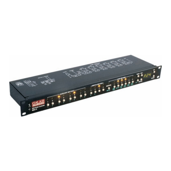
Congratulations for choosing our G LAB product! MIDI Guitar Controller (MGC) is the programmable switching device of effects’ loops (looper), the amp’s switcher and the MIDI devices’ controller in one for rack 19’ systems. MGC-6 can be controlled by any foot controller or other MIDI device sending the Program Change commands. -
Page 6: Diagram Of Devices Connectable To The Mgc-6
Diagram of devices connectable to the MGC-6... -
Page 7: Signal's Path Diagram
Signal’s path diagram Guitar signal, thru very high impedance (>10 MΩ) tuner buffer and separating transformer, is transmitted to TUNER output. It enables using of the tuner during playing. Controller features a switchable (by relay), true bypass input buffer circuit. Buffer which’s input impedance is consistent with tube amps boost the guitar signal power (without the voltage gain). -
Page 8: Buffer, Loops (Loop 1 To Loop 6), Switch Outputs And Aux Outputs
Buffer, loops (LOOP 1 to LOOP 6), SWITCH outputs and AUX outputs In order to switch on or off the buffer, particular effect LOOPs, SWITCH outputs and AUX outputs press the button placed under the indicator signalising their state. Lighting lamp means: the buffer is switched on, the effect connected to the loop is switched on, output shorting state of the particular SWITCH and high level of AUX output. -
Page 9: Preset's Storing
In order to not to send for given preset the Control Change command set the no value. Preset’s storing After modifying the preset’s parameters the preset should be saved. Controller enables saving modified preset under the same preset number or under a different number. Procedure of saving under the same number is shown below In case of saving the preset under a different number it is needed to press SAVE button, select the preset number by using the UP and DOWN buttons or numeric keys and after press the ENTER button. -
Page 10: Setup
SETUP Setup features the following parameters and functions: Cin - MIDI input channel number, Co1 - MIDI Program Change – 1 channel number, Co2 - MIDI Program Change – 2 channel number, Co3 - MIDI Program Change – 3 channel number Co4 - Control Change channel number Cno - CC Controller’s number, nio - MIDI output mode... -
Page 11: Programming Of The Channel Numbers For Midi Program Change 1, 2, 3
Programming of the channel numbers for MIDI Program Change 1, 2, 3 Next three positions in Setup defined as Co1, Co2, Co3 enable channel number programming successively for PRG CHG-1, PRG CHG-2, PRG CHG-3 commands. The available range is from 1 to 16. Displaying of the r letter with the channel number means that the number of this channel is already reserved (r) for other Program Change command. -
Page 12: Cc Controller's Number Programming
CC Controller’s number programming Controller’s No sent to the MIDI device is the same for all of the presets. The available range is from 0 to 127. MIDI OUTPUT mode programming MIDI OUTPUT of the controller can be switched on so-called Soft Thru mode. In this mode controller rewrite in unchanged state data from MIDI INPUT to MIDI OUTPUT. -
Page 13: Amp's Control Connecting
Amp’s control connecting The SW1 to SW4 outputs are used to control an amp by its footswitch input. Depending on the features of your amp they can be used for switching channels, switching on/off reverb or effects loop, BOOST function or other. -
Page 14: Aux A/B Switch Connection
6. For switching the loops serve the corresponding buttons of AUXILIARY SECTION (for AUX 1 buttons 1 and 2, for AUX 2 buttons 3 and 4, AUX 3 buttons 5 and 6 and for AUX 4 buttons 7 and 8). It is possible to connect four AUX 2xLOOPs to one MGC-6 maximally. -
Page 15: Midi Specification
Below you will find the example of the AUX A/B SWITCH connection. Guitar switch MIDI specification MIDI Input (MIDI IN) Controller can attend following commands: Program Change Sent value Program number Function 0 - 99 1 – 100 Preset number mute ON Control Change Controller’s number... -
Page 16: System Exclusive (Sysex) Type Messages
Controller’s number Controller’s value Function 0-63 AUX6 switching off 64-127 AUX6 switching on 0-63 AUX7 switching off 64-127 AUX7 switching on 0-63 AUX8 switching off 64-127 AUX8 switching on 0-63 Switch1 switching off 64-127 Switch1 switching on 0-63 Switch2 switching off 64-127 Switch2 switching on 0-63... -
Page 17: Midi Output (Midi Out)
F0 00 20 71 14 01 00 ... - message in this format is interpreted as memory content. If controller is set on mode enabling to receive this message the data will be received and the whole preset and setup memory will be overwritten. -
Page 18: Midi Output "Soft Thru" Mode
e) 1 data byte with the output channel number for the Program Change 2 (range 1-16) 1 data byte with the output channel number for the Program Change 3 (range 1-16) g) 1 data byte with the output channel number for the Control Change (range 1-16) h) 1 data byte with the information about the memory access lock state (1 - "UnP", 2 - "-20", 3 –... -
Page 19: Midi Implementation Chart
MIDI implementation chart G LAB MIDI Guitar Controller MGC-6 rev. 1.01 01.10.2008 Function Transmitted Recognised Basic Channel Default 1,2,3,4 Changed 1-16 1-16 Mode Default Messages Altered Note Number True Voice Velocity Note ON Note OFF After Touch Keys Channels Pitch Bend... -
Page 21: Emc/Emi & Certificate Of Conformity
ELZAB S.A., ul. Kruczkowskiego 39, 41-813 Zabrze, Poland, hereby declares on own responsibility that the following product: MGC-6 MIDI Guitar Controller (G LAB MGC-6) that is covered by this certificate and marked with CE 07 label conforms with following standards:... - Page 22 DO NOT PLACE THIS PRODUCT INTO THE WASTE CONTAINER! This device is marked with a cross-lined waste container symbol according to 2002/96/EU Directive on Waste Electric and Electronic Equipment. Such marking informs that after usage equipment can not be trashed together with other household waste.
Need help?
Do you have a question about the MGC-6 and is the answer not in the manual?
Questions and answers