Table of Contents
Advertisement
SERVICE MANUAL
Ver. 1.0 2018.01
• All of the units included in the HT-X9000F
(SA-X9000F/SA-WX9000F/Remote
control) or HT-XF9000 (SA-XF9000/SA-
WXF9000/Remote control) are required
to confi rming operation of SA-X9000F/
XF9000. Check in advance that you have
all of the units.
Note:
Be sure to keep your PC used for service and
checking of this unit always updated with the
latest version of your anti-virus software.
In case a virus affected unit was found during
service, contact your Service Headquarters.
COMPONENT MODEL NAME
Bar Speaker (Active Speaker System)
Subwoofer (Active Subwoofer)
• Please refer to service manual separately issued for Subwoofer.
Amplifier section
(X9000F: US)
POWER OUTPUT AND TOTAL HARMONIC
DISTORTION:
(FTC)
Front L + Front R:
With 4ohms loads, both channels
driven, from 200 - 20,000Hz; rated
35W per channel minimum RMS
power, with no more than 1% total
harmonic distortion from 250mW to
rated output.
POWER OUTPUT (reference)
Front L/Front R speaker blocks: 100W
(per channel at 4ohms, 1kHz)
(X9000F: CND/XF9000: AEP, UK)
POWER OUTPUT (rated)
Front L + Front R: 60W + 60W
(at 4ohms, 1kHz, 1% THD)
POWER OUTPUT (reference)
Front L/Front R speaker blocks: 100W
(per channel at 4ohms, 1kHz)
Inputs
HDMI IN*
ANALOG IN
TV IN (OPT)
Outputs
HDMI OUT (TV (ARC))*
*HDMI IN and HDMI OUT (TV (ARC)) jacks
support HDCP 2.2 protocol. HDCP 2.2 is
newly enhanced copyright protection
technology that is used to protect
content such as 4K movies.
HDMI Section
Connector
Type A (19pin)
9-896-483-01
2018A33-1
Sony Video & Sound Products Inc.
©
2018.01
HT-X9000F/XF9000
HT-X9000F
HT-XF9000
SA-X9000F
SA-XF9000
SA-WX9000F
SA-WXF9000
SPECIFICATIONS
USB section
(USB) port:
Type A (For connecting USB memory)
BLUETOOTH section
Communication system
BLUETOOTH Specification version 4.2
Output
BLUETOOTH Specification Power
Class1
Maximum communication range
1)
Line of sight approx. 30m
Maximum number of devices to be
registered
9 devices
Frequency band
2.4 GHz band (2.4GHz - 2.4835GHz)
Modulation method
FHSS (Freq Hopping Spread Spectrum)
2)
Compatible BLUETOOTH profiles
A2DP (Advanced Audio Distribution
Profile)
AVRCP (Audio Video Remote Control
Profile)
3)
Supported Codecs
4)
5)
SBC
, AAC
Transmission range (A2DP)
20 Hz - 20,000 Hz (Sampling frequency
32kHz, 44.1kHz, 48kHz)
1)
The actual range will vary depending on
factors such as obstacles between
devices, magnetic fields around a
microwave oven, static electricity,
cordless phone use, reception
sensitivity, the operating system,
software applications, etc.
2)
BLUETOOTH standard profiles indicate
the purpose of BLUETOOTH
communication between devices.
3)
Codec: Audio signal compression and
conversion format
4)
Abbreviation for Subband Codec
5)
Abbreviation for Advanced Audio
Coding
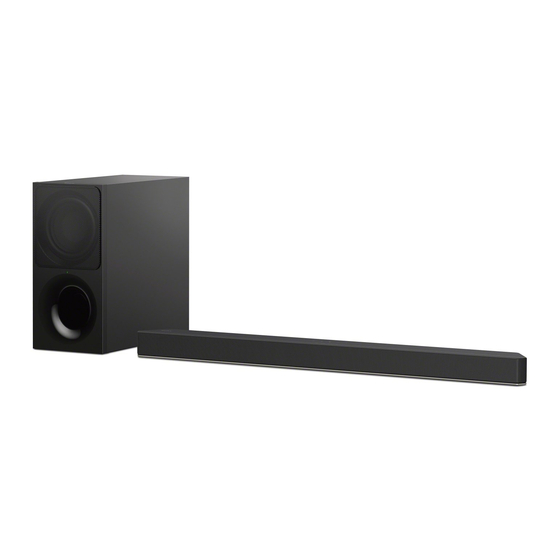
Photo: SA-X9000F
Front L/Front R speaker block section
Speaker system
Full Range speaker system, Acoustic
suspension
Speaker
40mm × 100mm (1 5/8 in. × 4 in) cone
type
General
Power requirements
120 V AC, 60 Hz (X9000F: US, CND)
220 V - 240 V AC, 50 Hz/60 Hz
(XF9000: AEP, UK)
Power consumption
On: 38W
[Bluetooth Standby] - [On]: Less than
2W
[Bluetooth Standby] - [Off]: Less than
0.5W
Dimensions* (approx.) (w/h/d)
930mm × 58mm × 85mm (36 5/8 in ×
2 3/8 in × 3 3/8 in)
*Not including projection portion
Mass (approx.)
2.5kg (5 33/64 lb)
ACTIVE SPEAKER SYSTEM
SA-X9000F/XF9000
US Model
Canadian Model
HT-X9000F/SA-X9000F
AEP Model
UK Model
HT-XF9000/SA-XF9000
Wireless Transmitter/
Receiver Section
Frequency band
2.4GHz (2.4000GHz - 2.4835GHz)
Modulation method
FHSS (Freq Hopping Spread Spectrum)
What's in the Box
equal to Premium High Speed HDMI
Cable with Ethernet) (1) (X9000F: US, CND)
Design and specifications are subject to
change without notice.
HT-X9000F/XF9000
SOUND BAR
SA-X9000F/XF9000
Advertisement
Table of Contents

Related Manuals for Sony SA-XF9000


Summarization of Contents
Specifications
Amplifier Section Details
Details of power output, total harmonic distortion, and input specifications.
USB Port Specifications
Details on the USB port functionality for connecting USB memory.
Bluetooth Connectivity Specifications
Specifications for Bluetooth version, output power, range, and profiles.
Speaker Block Specifications
Details on speaker system type, driver size, and cone type.
General Unit Specifications
Power requirements, dimensions, and mass of the unit.
Wireless Transmitter/Receiver Details
Specifications for wireless frequency band and modulation method.
Included Accessories
List of items included in the product package.
Servicing Notes
Unleaded Solder Information
Information on using lead-free solder, its characteristics, and handling.
Fuse Replacement Precautions
Important safety precautions to follow when replacing the fuse.
Operation Confirmation Preparation
Steps to prepare before confirming the operation of the unit.
Capacitor Discharge Procedure
Procedure to discharge capacitors safely to prevent electric shock.
Protection Mode Indicators
Explanation of how the system indicates protection mode activation.
Model Identification Methods
How to distinguish between different models using labels and part numbers.
Destination Code Abbreviations
Explanation of abbreviations used for model destination codes.
Serial Number Writing Procedure
Serial Number Writing Steps
Detailed step-by-step procedure for writing the serial number to the main board.
Wireless Connection (LINK) Procedure
Replacing Parts Requiring LINK
Procedures for reconnecting wireless link after replacing Bluetooth modules.
Wireless Connection Method
Steps to establish a wireless connection between the bar speaker and subwoofer.
Secure Link Method
Procedure for manually performing a secure wireless link.
Handling Single Unit Repairs
Guidance for performing wireless connection when only one unit is repaired.
Secure Link Cancellation
Methods to cancel the secure link for the bar speaker or subwoofer.
System Reset and Test Modes
System Resetting
How to reset system settings to their factory default values.
Advance Confirmation Notes
Important checks before repairing sound output or subwoofer linking issues.
Component Replacement Notes
Specific notes regarding the replacement of certain boards and parts.
Compound Spreading
Instructions for applying thermal compound to IC6006 and heat sink.
Touch Panel Malfunction Prevention
Measures to prevent malfunctions of the touch panel switch.
Disassembly Procedures
Disassembly Flow
Overall sequence of steps for disassembling the unit.
Top/Bottom Cabinet Block-1
Procedure for disassembling the top and bottom cabinet (Part 1).
Top/Bottom Cabinet Block-2
Procedure for disassembling the top and bottom cabinet (Part 2).
SK1 LED Board
Detailed steps for removing the SK1 LED board assembly.
Speaker Connection Cable (L-ch)
Procedure for disconnecting and removing the L-channel speaker cable.
Speaker Connection Cable (R-ch)
Procedure for disconnecting and removing the R-channel speaker cable.
Loudspeaker (L-ch/R-ch), Top Cabinet Assy
Steps to remove loudspeakers and the top cabinet assembly.
Bluetooth Module
Procedure for removing the Bluetooth module from the unit.
Holder (BT) Block
Steps to remove the holder securing the Bluetooth module.
SK1-WS-CHUKEI Board
Detailed steps for removing the SK1-WS-CHUKEI board.
SK1 IR REP (2) Board
Procedure for removing the SK1 IR REP (2) board.
Main Chassis Block-1
Procedure for disassembling the main chassis (Part 1).
Main Chassis Block-2
Procedure for disassembling the main chassis (Part 2).
Power-Supply Cord
Steps for safely removing and disconnecting the power supply cord.
Main Board-1
Procedure for removing the main board (Part 1).
Main Board-2
Procedure for removing the main board (Part 2).
SK1 IR REP (1) Board
Procedure for removing the SK1 IR REP (1) board.
SK1-JACK Board
Procedure for removing the SK1-JACK board.
SK1 AMP Board
Procedure for removing the SK1 AMP board.
Power Board
Procedure for removing the power board.
Main Board Service Position
Specific positioning guidance for servicing the main board.
Test Mode Operations
Button and LED Status Indicators
Identification of control buttons and status LED indicators on the unit.
Factory Settings Initialization
Procedure to reset all unit settings to their original factory defaults.
Firmware Update via USB
Steps for updating the unit's firmware using a USB memory device.
Forced Firmware Update Mode
Mode allowing for firmware upload or download operations.
Demo Mode Operation
How to activate and operate the demonstration mode of the unit.
Releasing Demo Mode
Methods to exit the demo mode and return to normal operation.
Built-in Demo and USB Playback
Instructions for playing built-in demo sound or content from USB.
Copying Demo Content from USB
Procedure to overwrite demo content with files from a USB memory.
Panel Test Procedure
Procedure to check the LED lighting state and key input functionality.
Service Mode Access and Functions
Entering Service Mode
Step-by-step guide on how to access the service mode.
Exiting Service Mode
Methods to safely release the service mode and turn off the unit.
Service Mode Main Functions
Overview of the primary functions available within the service mode.
Service Mode Menu Structure
Diagram illustrating the navigation and options within the service menu.
Viewing System Information
How to access and display detailed system information.
Serial Number Editing Function
Functionality for editing or verifying the unit's serial number.
Troubleshooting Guide
Troubleshooting Protection Mode
Diagnostic steps for issues related to protection mode activation.
Troubleshooting HDMI Output Issues
Steps to resolve problems with HDMI video and audio output.
Troubleshooting Sound Output Failure
Diagnostic procedures for when no sound is produced by the unit.
Troubleshooting Power On Issues
Steps to take when the unit fails to turn on.
Troubleshooting ARC Audio Issues
Specific guidance for resolving sound output problems via ARC.
Troubleshooting Subwoofer Link Errors
Steps to diagnose and fix issues with the subwoofer not linking.
Circuit Diagrams
HDMI Section Block Diagram
Block diagram illustrating the HDMI interface circuit.
Main Section Block Diagram
Block diagram of the main processing and control sections.
Amplifier Section Block Diagram
Block diagram of the audio amplifier and DSP sections.
Panel/Power Supply Block Diagram
Block diagram showing power supply and control panel circuits.
Main Board Printed Wiring Diagram
Component layout and connections for the main printed circuit board.
SK1-JACK/SK1-WS-CHUKEI PWB
Printed wiring board layouts for SK1-JACK and SK1-WS-CHUKEI boards.
SK1-JACK/SK1-WS-CHUKEI Schematic
Detailed schematic diagrams for SK1-JACK and SK1-WS-CHUKEI boards.
SK1 AMP Board Printed Wiring Diagram
Component layout and connections for the SK1 AMP printed circuit board.
SK1 AMP Board Schematic Diagram
Detailed schematic diagram for the SK1 AMP board.
Power Board Printed Wiring Diagram
Component layout and connections for the power supply board.
Power Board Schematic Diagram
Detailed schematic diagram for the power supply board.
Signal Waveform Analysis
Illustrations of key signal waveforms for diagnostic purposes.
Integrated Circuit Block Diagrams
Functional block diagrams of important integrated circuits.
Exploded Views and Parts Identification
Foot Section Exploded View
Exploded view of the unit's base, showing foot and mounting parts.
Top Cabinet Section Exploded View
Exploded view detailing components of the top cabinet assembly.
Bottom Cabinet Section Exploded View
Exploded view detailing components of the bottom cabinet assembly.
Main Board Section Exploded View
Exploded view showing the layout of the main board components.
SK1 AMP Board Section Exploded View
Exploded view showing the layout of the SK1 AMP board components.
Power Board Section Exploded View
Exploded view showing the layout of the power board components.
Electrical Parts List
Main Board Electrical Parts
List of electrical components and their part numbers for the main board.
Power Board Electrical Parts
List of electrical components and their part numbers for the power board.
SK1 AMP Board Electrical Parts
List of electrical components and their part numbers for the SK1 AMP board.
SK1 IR REP (1) Board Parts
List of electrical components for the SK1 IR REP (1) board.
SK1 IR REP (2) Board Parts
List of electrical components for the SK1 IR REP (2) board.
SK1-JACK Board Electrical Parts
List of electrical components for the SK1-JACK board.
SK1 LED Board Electrical Parts
List of electrical components for the SK1 LED board.
SK1-TOUCH Board Electrical Parts
List of electrical components for the SK1-TOUCH board.
SK1-WS-CHUKEI Board Electrical Parts
List of electrical components for the SK1-WS-CHUKEI board.
Included Accessories List
List of accessories provided with the product.
Revision History
Manual Revision Details
Record of changes and updates made to this service manual.
Need help?
Do you have a question about the SA-XF9000 and is the answer not in the manual?
Questions and answers