Sony SA-VE812ED Service Manual
Micro satellite system
Hide thumbs
Also See for SA-VE812ED:
- Operating instructions manual (28 pages) ,
- Operating instructions manual (28 pages)
Advertisement
QQ
3 7 63 1515 0
SERVICE MANUAL
The SA-VE812ED system consists of one unit
of SA-WMS815 and two units of SS-MS815.
The SA-VE815ED system consists of one unit
of SA-WMS815 and five units of SS-MS815.
For the U.S. model
AUDIO POWER SPECIFICATIONS
POWER OUTPUT AND TOTAL
HARMONIC DISTORTION :
TE
with 8 Ω loads both channels driven, from 20 - 150Hz; rated
L 13942296513
150 W per channel minimum RMS power, with no more
than 0.8% total harmonic distortion from 250 mW to rated
output.
SS-MS815 (
front, center, and rear speakers)
Speaker system
2 way, magnetically shielded
Speaker units
Tweeter :
1.9 cm (
Woofer :
5 cm (
type
Enclosure type
Bass reflex
8 Ω
Rated impedance
Power handling capacity
Maximum input power: 140 W
Sensitivity level
87 dB (1W, 1m)
Frequency range
120 Hz - 70,000 Hz
Dimensions (w/h/d)
When attached speaker grilles:
Approx. 86 × 169 × 130 mm
(3
When attached to supplied speaker stand:
Approx. 96 × 207 × 141 mm
(3
(Front (and rear)speakers)
Approx. 169 × 131 × 144 mm
(6
(Center speaker: pointed upwards)
Approx. 169 × 118 × 141 mm
(6
(Center speaker: pointed
downwards):
www
.
http://www.xiaoyu163.com
Mass
SA-WMS815 (subwoofer)
System
Speaker system
3
/
in.), dome type
Speaker unit
4
× 2
2
in.)
, balanced drive
Enclosure type
Continuous RMS power output
Reproduction frequency range
Inputs
LINE IN (input pin jack)
SPEAKER IN (input terminals)
Outputs
× 6
× 5
1
/
3
/
1
/
in.) each
LINE OUT (output pin jack)
2
4
8
SPEAKER OUT (output terminals)
General
× 8
× 5
7
1
5
Power requirements
/
/
/
in.) each,
8
4
8
European models :
Other models :
× 5
× 5
3
1
3
Power consumptions
/
/
/
in.),
4
4
4
Dimensions (w/h/d)
× 4
× 5
3
/
3
/
5
/
in.),
4
4
8
Mass
x
ao
y
i
http://www.xiaoyu163.com
SA-VE812ED/VE815ED/
8
WMS815/SS-MS815
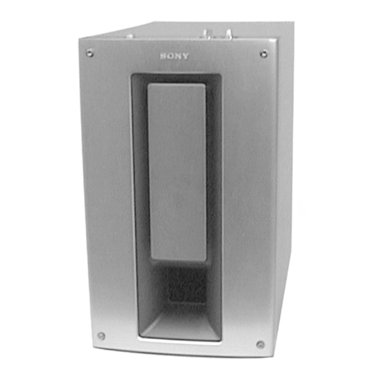
Photo : SA-WMS815
SPECIFICATIONS
When attached speaker grilles:
Approx. 1.3 kg (2lb 14oz) each
When attached to supplied speaker stand:
Q Q
3
6 7
1 3
Approx. 1.4 kg (3lb 1oz) each,
(Front (and rear) speakers)
Approx. 1.4 kg (3lb 1oz), (Center
speaker)
Active subwoofer, magnetically
shielded
Woofer : 20 cm (8 in.),
cone type
Advanded SAW type
150 W (8 Ω, 20 - 150 Hz, 0.8 %
THD)
24 Hz - 150 Hz
220 - 230 V AC, 50/60 Hz
120 V AC, 60 Hz
130 W
Approx. 230 × 395 × 495 mm
× 15
× 19
1
5
1
(9
/
/
/
in.), including
8
8
2
front grille
Approx. 17.5 kg
(37 lb 9 oz)
MICRO SATELLITE SYSTEM
u163
.
2 9
9 4
2 8
Canadian Model
AEP Model
Photo : SS-MS815
Supplied accessories
SA-VE815ED
Speaker stands (for the front and rear speakers) (4)
Speaker stand (for the center speaker) (1)
1 5
0 5
8
2 9
9 4
Screws (for the speaker stands) (10)
Washers (for the speaker stands) (10)
Plates (for the front and rear speaker stands) (4)
Speaker grilles (5)
Audio connecting cord (1)
Speaker connecting cords, 2.5 m (8 ft
Speaker connecting cords, 10 m (32 ft
SA-VE812ED
Speaker stands (for the front speakers) (2)
Screws (for the speaker stands) (4)
Washers (for the speaker stands) (4)
Plates (for the front speaker stands) (2)
Speaker grilles (2)
Audio connecting cord (1)
Speaker connecting cords, 2.5 m (8 ft
Design and specifications are subject to change
without notice
m
co
9 9
US Model
UK Model
E Model
2 8
9 9
2
1
/
in.) (5)
2
3
9
/
in.) (2)
4
1
2
/
in.) (4)
2
Advertisement
Table of Contents


Need help?
Do you have a question about the SA-VE812ED and is the answer not in the manual?
Questions and answers