Table of Contents
Advertisement
Quick Links
MAX-7 / NEO-7 / LEA-7
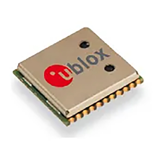
u-blox 7 GPS/GNSS modules
Hardware Integration Manual
Abstract
This document describes the features and specifications of the cost
effective and high-performance MAX-7, NEO-7 and LEA-7
GPS/GLONASS/QZSS modules featuring the u-blox 7 positioning
engine.
These compact, easy to integrate stand-alone GPS/GNSS receiver
modules combine exceptional GPS/GNSS performance with highly
flexible power, design, and connectivity options. Their compact
form factors and SMT pads allow fully automated assembly with
standard pick & place and reflow soldering equipment for cost-
efficient, high-volume production enabling short time-to-market.
www.u-blox.com
Advertisement
Table of Contents

Summarization of Contents
Quick Reference for u-blox 7 Modules
Layout Guidelines
PCB layout recommendations for optimal placement and routing of u-blox 7 modules.
Power Supply Connections
Details on connecting VCC, VCC_IO, V_BCKP, V_ANT, and VDD_USB pins.
Module Interfaces
Description of UART, USB, DDC, and SPI interfaces for module communication.
I/O Pin Functions
Explanation of various Input/Output pins and their functionalities on u-blox 7 modules.
u-blox 7 Hardware Description
Module Overview
General introduction to the features and capabilities of u-blox 7 GPS/GNSS modules.
Module Architecture
Explanation of the RF and digital block structure of the u-blox 7 positioning engine.
Operating Modes
Description of Continuous Mode and Power Save Mode operations for GNSS receivers.
Connecting Power Supplies
Detailed guidance on connecting various power supply pins for module operation.
Module Interfaces Explained
Technical specifications for UART, USB, DDC, and SPI communication interfaces.
I/O Pin Definitions
Detailed explanation of each I/O pin and its specific function on u-blox 7 modules.
Design Guidelines and Best Practices
Design Checklist
Essential checklist items for a successful u-blox 7 module design.
Minimal Design Considerations
Guidelines for creating compact and efficient designs using u-blox 7 modules.
PCB Layout Recommendations
Critical PCB layout advice for signal integrity and module performance.
Antenna Design and Supervision
Best practices for connecting and supervising antennas with u-blox 7 modules.
Recommended Components
List of recommended passive and active components for u-blox 7 designs.
Migrating to u-blox-7 Modules
Migrating u-blox 6 Designs
Recommended path for migrating from u-blox 6 to u-blox 7 modules.
Hardware Migration Notes
Key hardware compatibility and pinout changes for migration.
Software Migration Details
Information on software compatibility and unsupported messages during migration.
Product Handling and Reliability Precautions
Soldering Procedures
Recommendations for soldering u-blox 7 modules using reflow and other methods.
EOS, ESD, and EMI Precautions
Measures to prevent Electrostatic Discharge, Electrical Overstress, and EMI damage.
Product Testing and Validation
OEM Manufacturer Test Parameters
Guidance for OEMs on testing integrated u-blox 7 devices.
System Sensitivity Testing
Methods and guidelines for testing GPS/GNSS receiver sensitivity.
Appendix and Support Information
Related Documents
List of essential documents for further reference and technical details.
Contact Information
Contact details for u-blox technical support and sales offices worldwide.


Need help?
Do you have a question about the NEO-7 Series and is the answer not in the manual?
Questions and answers