Table of Contents
Advertisement
Quick Links
Advertisement
Chapters
Table of Contents

Related Manuals for Ditch Witch FM13X


Summary of Contents for Ditch Witch FM13X
- Page 1 FM13V/FM13X Operator’s Manual 053-1125 Issue 3.0 ORIGINAL INSTRUCTION...
-
Page 2: Table Of Contents
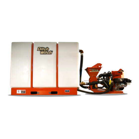
FM13V/FM13X Operator’s Manual Overview - 1 Overview Chapter Contents Serial Number Location ..... . 2 Intended Use ......3 Unit Components . -
Page 3: Serial Number Location
FM13V/FM13X Operator’s Manual Overview - 2 Serial Number Location Serial Number Location j65om001w.eps Record serial numbers and date of purchase in spaces provided. Fluid unit serial number is located as shown. Item date of manufacture date of purchase fluid unit serial number... -
Page 4: Intended Use
0° to 115°F (-18° to 46°C). Use in any other way is considered contrary to the intended use. The FM13V/FM13X can be used with Ditch Witch drilling units and locating equipment. It should be operated, serviced, and repaired only by persons familiar with its particular characteristics and acquainted with the relevant safety procedures. -
Page 5: About This Manual
FM13V/FM13X Operator’s Manual Overview - 4 About This Manual About This Manual This manual contains information for the proper use of this machine. See the beige Operation Overview pages for basic operating procedures. Cross references such as “See page 50” will direct you to detailed procedures. -
Page 6: Foreword
If you sell your equipment, be sure to give this manual to the new owner. If you need a replacement copy, contact your Ditch Witch dealer. If you need assistance in locating a dealer, visit our website at www.ditchwitch.com or write to the following address: The Charles Machine Works, Inc. - Page 7 Part number 053-1125 Copyright 2007, 2014, 2017 by The Charles Machine Works, Inc. and Ditch Witch are registered trademarks of The Charles Machine Works, Inc. This product and its use may be covered by one or more patents at http://patents.charlesmachine.works.
- Page 8 FM13V/FM13X Operator’s Manual Contents - 7 Contents Overview machine serial number, information about the type of work this machine is designed to perform, basic machine components, and how to use this manual Foreword part number, revision level, and publication date of this manual, and factory contact...
- Page 9 FM13V/FM13X Operator’s Manual Contents - 8...
-
Page 10: Safety
FM13V/FM13X Operator’s Manual Safety - 9 Safety Chapter Contents Guidelines ....... . 10 California Proposition 65 Warning . -
Page 11: Guidelines
• Fully inspect equipment before operating. Repair or replace any worn or damaged parts. Replace missing or damaged safety shields and safety signs. Contact your Ditch Witch dealer for assistance. • Use equipment carefully. Stop operation and investigate anything that does not look or feel right. -
Page 12: Emergency Procedures
FM13V/FM13X Operator’s Manual Safety - 11 Emergency Procedures Emergency Procedures Jobsite hazards could cause death or serious injury. Use correct equipment and work methods. Use and maintain proper safety equipment. Before operating any equipment, review emergency procedures and check that all safety precautions have been taken. -
Page 13: If An Electric Line Is Damaged
FM13V/FM13X Operator’s Manual Safety - 12 Emergency Procedures If an Electric Line is Damaged If you suspect an electric line has been damaged and you are on truck or trailer, DO NOT MOVE. Remain on truck or trailer and take the following actions. The order and degree of action will depend on the situation. -
Page 14: If A Gas Line Is Damaged
FM13V/FM13X Operator’s Manual Safety - 13 Emergency Procedures If a Gas Line is Damaged Fire or explosion possible. Fumes could ignite and cause burns. No smoking, no flame, no spark. 275-419 (2P) Explosion possible. Serious injury or equipment damage could occur. -
Page 15: If A Fiber Optic Cable Is Damaged
FM13V/FM13X Operator’s Manual Safety - 14 Emergency Procedures If a Fiber Optic Cable is Damaged Do not look into cut ends of fiber optic or unidentified cable. Vision damage can occur. Contact utility company. If Machine Catches on Fire Perform emergency shutdown procedure and then take the following actions. The order and degree of action will depend on the situation. -
Page 16: Safety Alert Classification
FM13V/FM13X Operator’s Manual Safety - 15 Safety Alert Classifications Safety Alert Classifications These classifications and the icons defined on the following pages work together to alert you to situations which could be harmful to you, jobsite bystanders or your equipment. When you see these words and icons in the book or on the machine, carefully read and follow all instructions. - Page 17 FM13V/FM13X Operator’s Manual Safety - 16 Machine Safety Alerts Machine Safety Alerts Fire or explosion possible. Fumes could ignite and cause burns. No smoking, no flame, no spark. Lift point. See Transport chapter for more information. Electric shock will cause death or serious injury.
- Page 18 FM13V/FM13X Operator’s Manual Safety - 17 Machine Safety Alerts Tanks Electric shock will cause death or serious injury. Stay away. Tiedown location. See Transport chapter for more information. Lift point. See Transport chapter for more information.
-
Page 19: Machine Safety Alerts
FM13V/FM13X Operator’s Manual Safety - 18 Machine Safety Alerts... -
Page 20: Controls
FM13V/FM13X Operator’s Manual Controls - 19 Controls Chapter Contents Power Unit ....... 20... - Page 21 FM13V/FM13X Operator’s Manual Controls - 20 Power Unit Power Unit j65om003w.eps 1. Hourmeter 5. Battery disconnect switch (electric start only) 2. Secondary fuel shutoff valve 6. Ignition 3. Choke 7. Rope start 4. Throttle Item Description Notes 1. Hourmeter Displays engine operating Hourmeter runs when ignition switch time and engine rpm.
- Page 22 FM13V/FM13X Operator’s Manual Controls - 21 Power Unit Item Description Notes 2. Secondary fuel shutoff To allow fuel flow, open valve Fuel shutoff is automatic on electric valve (move left/right). start units. To shut off fuel flow, close valve (move left/right).
- Page 23 FM13V/FM13X Operator’s Manual Controls - 22 Power Unit Item Description Notes 6. Ignition switch To start engine, insert key and Only on electric start units. turn clockwise. To stop engine, turn key counterclockwise. c00ic254w.eps 7. Rope start To start engine, pull rope.
- Page 24 FM13V/FM13X Operator’s Manual Controls - 23 Mixing Unit Mixing Unit j65om004w.eps 1. Mixing jet valve 4. Liquid additive pickup valve 2. Pump drain valve 5. Discharge valve 3. Dry chemical hopper valve 6. Mixing venturi valve Item Description Notes 1. Mixing venturi plug To allow flow from pump to mixing venturi, open valve.
- Page 25 FM13V/FM13X Operator’s Manual Controls - 24 Mixing Unit Item Description Notes 3. Dry chemical hopper To allow flow from hopper to IMPORTANT: valve mixing venturi, open valve. • Open valve only when pouring To stop flow from hopper to additives into hopper for mixing.
-
Page 26: Operation Overview
FM13V/FM13X Operator’s Manual Operation Overview - 25 Operation Overview Chapter Contents Planning ....... . . 26 Setting Up at Jobsite . -
Page 27: Planning
FM13V/FM13X Operator’s Manual Operation Overview - 26 Planning Planning 1. Gather information about jobsite (page 30). 2. Inspect jobsite (page 30). 3. Check supplies and prepare equipment (page 32). Setting Up at Jobsite 1. Prepare jobsite (page 31). 2. Position fluid unit and connect to drilling unit. See drilling unit operator’s manual. - Page 28 FM13V/FM13X Operator’s Manual Operation Overview - 27 Mixing Fluid 4. Start engine. • For electric start units, turn ignition switch to start position and release when engine starts. • For rope start units, turn engine stop switch to ON and pull rope.
-
Page 29: Transferring Fluid
FM13V/FM13X Operator’s Manual Operation Overview - 28 Transferring Fluid Transferring Fluid Electric shock. Contacting electric lines will cause death or serious injury. Know location of lines and stay away. To help avoid injury: Remember that if electrical strike occurs while fluid hose is connected to drilling unit, fluid system will also become electrified. -
Page 30: Prepare
FM13V/FM13X Operator’s Manual Prepare - 29 Prepare Chapter Contents Gather Information ......30 • Arrange for Traffic Control ........30 •... -
Page 31: Gather Information
FM13V/FM13X Operator’s Manual Prepare - 30 Gather Information Gather Information A successful job begins before the excavation. The first step in planning is reviewing information already available about the job and jobsite. Arrange for Traffic Control If working near a road or other traffic area, contact local authorities about safety procedures and regulations. -
Page 32: Inspect Jobsite
FM13V/FM13X Operator’s Manual Prepare - 31 Inspect Jobsite Inspect Jobsite • Follow U.S. Department of Labor regulations on excavating and trenching (Part 1926, Subpart P) and other similar regulations. • Mark proposed path with white paint and have underground utilities located before working. -
Page 33: Check Supplies And Prepare Equipment
FM13V/FM13X Operator’s Manual Prepare - 32 Check Supplies and Prepare Equipment Check Supplies and Prepare Equipment Assemble Accessories Fire Extinguisher If required, mount a fire extinguisher near the power unit but away from possible points of ignition. The fire extinguisher should always be classified for both oil and electric fires. It should meet legal and regulatory requirements. -
Page 34: Transport
FM13V/FM13X Operator’s Manual Transport - 33 Transport Chapter Contents Lift ........34 •... - Page 35 FM13V/FM13X Operator’s Manual Transport - 34 Lift Lift Crushing weight. If load falls or moves it could kill or crush you. Use proper procedures and equipment or stay away. Points Lifting points are identified by lifting decals. Lifting at other points is unsafe and can damage machinery.
- Page 36 FM13V/FM13X Operator’s Manual Transport - 35 Haul Mixing Unit Use crane capable of supporting the equipment's size and weight. See “Specifications” on page 57 or measure and weigh equipment before lifting. 1. Lift mixing unit by attaching chains to lift points on top of pump.
- Page 37 FM13V/FM13X Operator’s Manual Transport - 36 Haul...
-
Page 38: Drilling Fluid Concepts
FM13V/FM13X Operator’s Manual Drilling Fluid Concepts - 37 Drilling Fluid Concepts Chapter Contents Recommended Products ....38 Guidelines ....... . 38 Polymer . -
Page 39: Recommended Products
Con-Det™ water-soluble cleaning solution (p/n 259-810) Guidelines ® Match drilling fluid to soil type. This chart is meant as a guideline only. See your local Ditch Witch dealer for soil conditions and drilling fluid recommendations for your area. Soil type... -
Page 40: Polymer
FM13V/FM13X Operator’s Manual Drilling Fluid Concepts - 39 Polymer Polymer This drilling fluid additive provides excellent lubrication and increases viscosity in average soils and heavy clay. In swelling clay, polymer can reduce swelling that traps pipe in the bore. There are two types of polymer: •... -
Page 41: Mixtures
FM13V/FM13X Operator’s Manual Drilling Fluid Concepts - 40 Mixtures Mixtures NOTICE: Bentonite does not mix well in water containing polymer. To use both, mix bentonite first, then add polymer. • If chemicals are added in the wrong order, they will not mix properly and will form clumps. -
Page 42: Basic Fluid Recipes
FM13V/FM13X Operator’s Manual Drilling Fluid Concepts - 41 Mixtures Basic Fluid Recipes Soil type Mixture/100 gal (378 L) of water Notes fine sand 35 lb (16 kg) Bore-Gel coarse sand 35 lb (16 kg) Bore-Gel Add .5 lb (225 g) of Quik-Trol for .5 lb (225 g) No-Sag... -
Page 43: Drilling Fluid Requirements
FM13V/FM13X Operator’s Manual Drilling Fluid Concepts - 42 Drilling Fluid Requirements Drilling Fluid Requirements 1. Determine drilling conditions and choose appropriate drilling fluid mix. 2. Estimate amount of supplies needed and check availability. • Drilling fluid • Water supply. If more water than can be carried with the unit will be needed, arrange to transport additional water. -
Page 44: Complete The Job
FM13V/FM13X Operator’s Manual Complete the Job - 43 Complete the Job Chapter Contents Rinse Equipment ......44... - Page 45 FM13V/FM13X Operator’s Manual Complete the Job - 44 Rinse Equipment Rinse Equipment Spray water onto equipment to remove dirt and mud. Disconnect Disconnect and store hoses and cables.
-
Page 46: Service
FM13V/FM13X Operator’s Manual Service - 45 Service Chapter Contents Service Precautions ......46 • Welding Precaution ........46 •... -
Page 47: Service Precautions
FM13V/FM13X Operator’s Manual Service - 46 Service Precautions Service Precautions Misuse of machine can cause death or serious injury. Read and understand operator’s manual and all other safety instructions before use. To help avoid injury: • Unless otherwise instructed, all service should be performed with engine off. -
Page 48: Recommended Lubricants/Service Key
For more information on engine lubrication and maintenance, see your Honda engine manual. NOTICE: • Use only genuine Ditch Witch parts, filters, approved lubricants, TJC, and approved coolants to maintain warranty. • Use the “Service Record” on page 63 to record all required service to your machine. -
Page 49: Each Use
FM13V/FM13X Operator’s Manual Service - 48 Each Use Each Use Check Engine Oil Level Check engine oil at dipstick before each use. If low, add GEO until oil level is at highest line on dipstick. IMPORTANT: For more information on engine oil, see “Recommended Lubricants/Service... -
Page 50: 20 Hour
FM13V/FM13X Operator’s Manual Service - 49 20 Hour 20 Hour Change Engine Oil (initial) Change engine oil after the first 10 hours of operation and every 100 hours thereafter. 1. Drain at plug (1) while oil is still warm. 2. Replace plug. -
Page 51: Hour
FM13V/FM13X Operator’s Manual Service - 50 100 Hour 100 Hour Location Task Notes Change inline fuel filter Check fan belt tension Change engine oil Check spark plug Change Fuel Filters Change inline fuel filter every 100 hours. Change Air Filter Change air filter elements every 100 hours. - Page 52 FM13V/FM13X Operator’s Manual Service - 51 100 Hour Change Engine Oil and Filter Change engine oil after the first 20 hours of operation and every 100 hours thereafter. 1. Drain at plug (1) while oil is still warm. 2. Replace plug.
-
Page 53: Hour
Check idle speed every 300 hours and adjust as needed. ® See Ditch Witch dealer or Honda serving dealer. Check and Adjust Valve Clearance Check valve clearance every 300 hours and adjust as needed. See Ditch Witch dealer or Honda serving dealer. -
Page 54: As Needed
FM13V/FM13X Operator’s Manual Service - 53 As Needed As Needed Check Battery (Electric Start Only) Check battery as needed. Keep battery clean and terminals free of corrosion. To clean: 1. Turn battery disconnect switch, if equipped, to the off position. - Page 55 FM13V/FM13X Operator’s Manual Service - 54 As Needed...
- Page 56 FM13V/FM13X Operator’s Manual Specifications - 55 Specifications j65om012w.eps Dimensions with 1000-gal (3785-L) tank U.S. Metric Length (as shown; variable with layout flexibility) 80 in 4.57 m Width (as shown; variable with layout flexibility) 42 in 1.07 m Height, without fill pipe 72 in 1.83 m...
- Page 57 FM13V/FM13X Operator’s Manual Specifications - 56 Performance U.S. Metric Centrifugal pump suction port diameter 3 in 76 mm Centrifugal pump discharge port diameter 3 in 76 mm Maximum fluid pressure 50 psi 3.4 bar Maximum pump discharge rate (water) 270 gpm 1020 L/min Maximum flow rate to drilling unit (42 viscosity fluid @ 30 psi/2.1 bar...
-
Page 58: Specifications
FM13V/FM13X Operator’s Manual Specifications - 57 Fluid Capacities U.S. Metric Fuel tank 6.0 gal 23 L Engine oil, including filter 1.2 qt 1.1 L Noise levels This machine can generate sound levels exceeding 80 dB. Always wear appropriate hearing protection when operating machine. - Page 59 FM13V/FM13X Operator’s Manual Specifications - 58...
-
Page 60: Support
Return damaged parts to dealer for inspection and warranty consideration if in warranty time frame. Order genuine Ditch Witch replacement or repair parts from your authorized Ditch Witch dealer. Use of another manufacturer's parts may void warranty consideration. - Page 61 Defects will be determined by an inspection within thirty (30) days of the date of failure of the product or part by Ditch Witch Product Support (DWPS) or its authorized dealer. DWPS will provide the location of its inspection facilities or its nearest authorized dealer upon inquiry.
-
Page 64: Service Record
FM13V/FM13X Operator’s Manual Service Record - 63 Service Record Service Performed Date Hours... - Page 65 FM13V/FM13X Operator’s Manual Service Record - 64 Service Performed Date Hours...
Need help?
Do you have a question about the FM13X and is the answer not in the manual?
Questions and answers