
Subscribe to Our Youtube Channel
Related Manuals for Ditch Witch JT40


Summary of Contents for Ditch Witch JT40
- Page 1 JT40/JT40 All Terrain HRC and LRC Operator’s Manual Issue 1.0 053-2966 Original Instruction...
-
Page 2: Table Of Contents
JT40/JT40 All Terrain Operator’s Manual Overview - 1 Overview Chapter Contents Serial Number Location ..... . 2 Intended Use ....... 3 Equipment Modification . -
Page 3: Serial Number Location
JT40/JT40 All Terrain Operator’s Manual Overview - 2 Serial Number Location Serial Number Location Record serial numbers and date of purchase in spaces provided. Drilling unit serial number is located as shown. j59om059w.eps Item date of manufacture date of purchase... -
Page 4: Intended Use
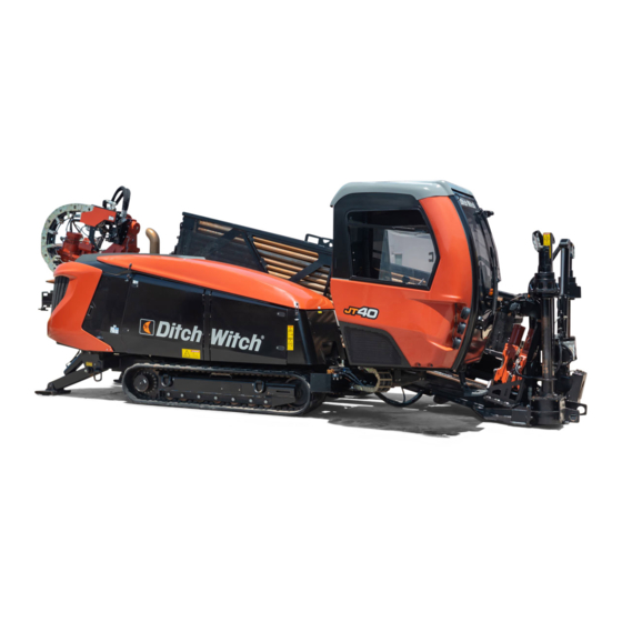
Intended Use Intended Use The JT40 is a self-contained horizontal directional drilling unit designed to install buried cable and pipe to distances of 600-1000’ (183-305 m) depending on diameter of drill pipe and soil conditions. Its All Terrain version is designed to drill through rock, cobblestone, broken rock, gravel, and caliche. -
Page 5: Unit Components
JT40/JT40 All Terrain Operator’s Manual Overview - 4 Unit Components Unit Components j59om060w.eps 1. Operator’s station 7. Pipeloader 2. Spindle 8. Vise wrenches 3. Carriage 9. Anchoring system 4. Drill frame ® 10. DrillLok light (green) 5. Stabilizer 11. Wireless remote control light (clear) 6. -
Page 6: Fcc Statement - Internal Transmitter
JT40/JT40 All Terrain Operator’s Manual Overview - 5 FCC Statement - Internal Transmitter FCC Statement - Internal Transmitter U.S. This device complies with Part 15 of the FCC Rules. Operation is subject to the following two conditions: (1) this device may not cause harmful interference, and (2) this device must accept any interference received, including interference that may cause undesired operation. -
Page 7: Operator Orientation
JT40/JT40 All Terrain Operator’s Manual Overview - 6 Operator Orientation Operator Orientation IMPORTANT: Top view of unit is shown. 1. Front of unit 2. Right side of unit 3. Rear of unit 4. Left side of unit j59om010w.eps About This Manual This manual contains information for the proper use of this machine. -
Page 8: Foreword
If you sell your equipment, be sure to give this manual to the new owner. If you need a replacement copy, contact your Ditch Witch dealer. If you need assistance in locating a dealer, visit our website at www.ditchwitch.com or write to the following address: The Charles Machine Works, Inc. - Page 9 JT40/JT40 All Terrain Operator’s Manual Foreword - 8 JT40/JT40 All Terrain HRC & LRC Operator’s Manual Issue number 1.0/OM-4/16 Part number 053-2966 Copyright 2017 by The Charles Machine Works, Inc. , Subsite, Jet Trac, Fluid Miser, Power Pipe, Rockmaster, SaverLok, SaverLok System, and DrillLok are registered trademarks of The Charles Machine Works, Inc.
- Page 10 JT40/JT40 All Terrain Operator’s Manual Contents - 9 Contents Overview machine serial number, information about the type of work this machine is designed to perform, basic machine components, and how to use this manual Foreword part number, revision level, and publication date of this manual, and factory contact...
- Page 11 Support the warranty policy for this machine, and procedures for obtaining warranty consideration and training Service Record a record of major service performed on the machine Appendix ® additional information about Ditch Witch equipment...
-
Page 12: Safety
JT40/JT40 All Terrain Operator’s Manual Safety - 11 Safety Chapter Contents Guidelines ....... . 12 California Proposition 65 Warning . -
Page 13: Guidelines
• Fully inspect equipment before operating. Repair or replace any worn or damaged parts. Replace missing or damaged safety shields and safety signs. Contact your Ditch Witch dealer for assistance. • Use equipment carefully. Stop operation and investigate anything that does not look or feel right. -
Page 14: Emergency Procedures
JT40/JT40 All Terrain Operator’s Manual Safety - 13 Emergency Procedures Emergency Procedures Jobsite hazards could cause death or serious injury. Use correct equipment and work methods. Use and maintain proper safety equipment. Before operating any equipment, review emergency procedures and check that all safety precautions have been taken. -
Page 15: If An Electric Line Is Damaged
JT40/JT40 All Terrain Operator’s Manual Safety - 14 Emergency Procedures If an Electric Line is Damaged If you suspect an electric line has been damaged and you are on drilling unit or bonded equipment, DO NOT MOVE. Remain on drilling machine and take the following actions. The order and degree of action will depend on the situation. -
Page 16: If A Gas Line Is Damaged
JT40/JT40 All Terrain Operator’s Manual Safety - 15 Emergency Procedures If a Gas Line is Damaged Fire or explosion possible. Fumes could ignite and cause burns. No smoking, no flame, no spark. 275-419 (2P) Explosion possible. Serious injury or equipment damage could occur. -
Page 17: If A Fiber Optic Cable Is Damaged
JT40/JT40 All Terrain Operator’s Manual Safety - 16 Emergency Procedures If a Fiber Optic Cable is Damaged Do not look into cut ends of fiber optic or unidentified cable. Vision damage can occur. Contact utility company. If Machine Catches on Fire Perform emergency shutdown procedure and then take the following actions. -
Page 18: Safety Alert Classification
JT40/JT40 All Terrain Operator’s Manual Safety - 17 Safety Alert Classifications Safety Alert Classifications These classifications and the icons defined on the following pages work together to alert you to situations which could be harmful to you, jobsite bystanders or your equipment. When you see these words and icons in the book or on the machine, carefully read and follow all instructions. -
Page 19: Machine Safety Alerts
JT40/JT40 All Terrain Operator’s Manual Safety - 18 Machine Safety Alerts Machine Safety Alerts DANGER stripe decal. See Parts Manual for replacement part numbers. Tiedown location. See Transport chapter for more information. 274-318 Crushing weight. Place cylinder lock on extended cylinder and secure. - Page 20 JT40/JT40 All Terrain Operator’s Manual Safety - 19 Machine Safety Alerts Moving tools will kill or injure. Never use pipe wrenches on drill string. 273-278 Fire or explosion possible. Do not use starter fluid. 273-459 (2P), 274-206 (2P), 700-206 (2P) Read operator’s manual.
- Page 21 JT40/JT40 All Terrain Operator’s Manual Safety - 20 Machine Safety Alerts Equipment can be operated by remote control. Stay away. 270-6035 Jobsite hazards could cause death or serious injury. Use correct equipment and work methods. Use and maintain proper safety equipment.
-
Page 22: Controls
JT40/JT40 All Terrain Operator’s Manual Controls - 21 Controls Chapter Contents Set-Up Console ......22 •... -
Page 23: Set-Up Console
JT40/JT40 All Terrain Operator’s Manual Controls - 22 Set-Up Console Set-Up Console Controls j59om001w.eps 1. Cold start wait indicator 4. Wash wand switch 2. Ignition switch 5. Left track switch 3. Engine shutdown override switch 6. Right track switch Item... - Page 24 JT40/JT40 All Terrain Operator’s Manual Controls - 23 Set-Up Console Item Description Notes 2. Ignition switch To start engine, insert key and IMPORTANT: turn clockwise. • Restart engine with ignition switch To stop engine, turn key after it has been turned off with counterclockwise.
-
Page 25: Wireless Remote Controller
JT40/JT40 All Terrain Operator’s Manual Controls - 24 Set-Up Console Wireless Remote Controller 1. Communication link indicator 7. Drive mode switch 2. Power status indicator 8. Left multifunction joystick 3. Power/start/horn switch 9. Throttle switch 4. Right multifunction joystick 10. Menu select switch 5. - Page 26 JT40/JT40 All Terrain Operator’s Manual Controls - 25 Set-Up Console Item Description Notes 1. Communication link Indicates the status of the An active communication link is indicator transmitter and receiver link. required for wireless control. • Blinking yellow indicates no communication link.
- Page 27 JT40/JT40 All Terrain Operator’s Manual Controls - 26 Set-Up Console Item Description Notes 6. Engine stop To stop engine, press red IMPORTANT: To restart engine, turn button. ignition switch off and then back on. 7. Drive mode switch To select normal driving mode (high), move up.
- Page 28 JT40/JT40 All Terrain Operator’s Manual Controls - 27 Set-Up Console Multifunction Joystick Control Modes The multifunction joystick controls are capable of controlling multiple systems by selecting various modes. IMPORTANT: To switch between modes, see “Menu select switch” on page 26.
- Page 29 JT40/JT40 All Terrain Operator’s Manual Controls - 28 Set-Up Console Item Description Notes 5. Left anchor dual To raise, push up. joystick control To lower, push down. c00ic209w.eps 6. Right anchor dual To raise, push up. joystick control To lower, push down.
- Page 30 JT40/JT40 All Terrain Operator’s Manual Controls - 29 Set-Up Console Multifunction Joystick (Left) Modes Item Description Notes 1. Dual joystick ground To move right track forward, • Operator presence switch must drive control move lever forward. be pressed and operator seat must be empty for control to work.
- Page 31 JT40/JT40 All Terrain Operator’s Manual Controls - 30 Set-Up Console Item Description Notes 5. Right anchor dual To rotate counterclockwise, joystick control push up. To rotate clockwise, push down. c00ic210w.eps...
-
Page 32: Left Control Console
JT40/JT40 All Terrain Operator’s Manual Controls - 31 Left Control Console Left Control Console Pipeloading Controls j59om004w.eps 1. Remove pipe control 7. Pipe lift switch 2. Select previous row control 8. Wrench control 3. Select next row control 9. Pipe lubricator switch 4. - Page 33 JT40/JT40 All Terrain Operator’s Manual Controls - 32 Left Control Console Item Description Notes 1. Remove pipe control To select automated “remove See “Enable Automated Pipeloader pipe” pipeloader function, System” on page 130. press. To use manual pipeloader controls, press again.
- Page 34 JT40/JT40 All Terrain Operator’s Manual Controls - 33 Left Control Console Item Description Notes 6. Pipe shuttle switch To move toward pipe box, press top. To move toward spindle, press bottom. To stop shuttles, release. 7. Pipe lift switch To raise, press top.
- Page 35 JT40/JT40 All Terrain Operator’s Manual Controls - 34 Left Control Console Item Description Notes 10. Set/Resume switch To resume operation or See “Cruise Control” on page 186. increase operation levels, press top. See “AutoCarve control” on page 37. RESUME To set operating conditions or See “Pipeloader”...
-
Page 36: Drilling/Operation Controls
JT40/JT40 All Terrain Operator’s Manual Controls - 35 Left Control Console Drilling/Operation Controls j59om005w.eps 1. Jog clockwise control (AT only) 8. Autothrottle control 2. Manual inner spindle control (AT only) 9. Remote engine start control 3. Automated inner spindle control (AT only) 10. - Page 37 JT40/JT40 All Terrain Operator’s Manual Controls - 36 Left Control Console Item Description Notes 1. Jog clockwise control To turn inner rod clockwise at a fixed speed, press. To stop, press again. c00ic185w.eps 2. Manual inner spindle To turn on, press.
- Page 38 JT40/JT40 All Terrain Operator’s Manual Controls - 37 Left Control Console Item Description Notes 5. AutoCarve control To enable autocarve, press. IMPORTANT: To disable autocarve, press • Use rotary operation control to again. adjust carve window. See “Rotary operation control” on page 39.
- Page 39 JT40/JT40 All Terrain Operator’s Manual Controls - 38 Left Control Console Item Description Notes 8. Autothrottle control To enable autothrottle mode, Autothrottle mode slows the engine to AUTO press. low throttle after 15 seconds of inactivity involving thrust, rotation, To disable autothrottle mode, drilling fluid flow, or pipeloader press again.
- Page 40 JT40/JT40 All Terrain Operator’s Manual Controls - 39 Left Control Console Item Description Notes 10. Rotary operation Turn knob to control the control following functions: Press and turn knob to allow finer control of the following functions. See “Manual inner spindle control” on...
- Page 41 JT40/JT40 All Terrain Operator’s Manual Controls - 40 Left Control Console Item Description Notes 11. Automated inner To turn on, press. IMPORTANT: spindle selector To turn off, press again. • Drilling mode switch must be in AT position. See “Engine Compartment”...
- Page 42 JT40/JT40 All Terrain Operator’s Manual Controls - 41 Left Control Console Item Description Notes 14. Outer spindle brake To engage, press. Prevents outer spindle from rotating control when inner spindle or mud motor are To disengage, press again. in use.
-
Page 43: Miscellaneous Controls
JT40/JT40 All Terrain Operator’s Manual Controls - 42 Left Control Console Miscellaneous Controls j59om076w.eps 1. ESID alarm interrupt/self-test switch 2. Horn Item Description Notes 1. ESID alarm interrupt/ To turn off strike alarm at IMPORTANT: self-test switch drilling unit, press top. - Page 44 JT40/JT40 All Terrain Operator’s Manual Controls - 43 Left Control Console Item Description Notes 2. Horn Press and hold to sound horn. c00ic194w.eps...
-
Page 45: Right Control Console
JT40/JT40 All Terrain Operator’s Manual Controls - 44 Right Control Console Right Control Console j59om003w.eps 1. Carriage control joystick 6. USB port 2. Drilling fluid quick fill switch 7. Lower/Remote* display 3. Remote engine stop switch 8. Upper display 4. Drilling fluid pump switch 9. - Page 46 JT40/JT40 All Terrain Operator’s Manual Controls - 45 Right Control Console Item Description Notes 2. Drilling fluid quick fill For full pump flow to fill pipe IMPORTANT: Overrides fluid control switch with fluid, press and hold. setting for full pump flow. Also...
- Page 47 JT40/JT40 All Terrain Operator’s Manual Controls - 46 Right Control Console Item Description Notes 7. Lower/Remote display Displays graphic symbols for For more information see “Lower indicators and conditions. Display” on page 47. ® See tracking system operator’s If using a Subsite manual for more information.
-
Page 48: Lower Display
JT40/JT40 All Terrain Operator’s Manual Controls - 47 Right Control Console Lower Display 10:15 am 12.2 Volts 2800 LOAD 0 6 5 j59om077w.eps ® IMPORTANT: If unit is equipped with Subsite Electronics COMMANDER™ 7 display, engine information will be displayed on screen in addition to tracker information. - Page 49 JT40/JT40 All Terrain Operator’s Manual Controls - 48 Right Control Console Item Description Notes 1. Tachometer Displays engine speed. 2. Engine oil pressure Displays engine oil Full load reading should be 60-80 psi indicator/numeric pressure. (4.1-5.5 bar). display 3. Engine coolant Displays engine Normal coolant temperature is 160°-...
- Page 50 JT40/JT40 All Terrain Operator’s Manual Controls - 49 Right Control Console Item Description Notes 11. Engine warning/stop Lights when engine indicator needs attention. Lights when operator needs to stop engine. 12. Engine load display Displays engine load. 13. Hourmeter Displays number of hours...
-
Page 51: Upper Display
JT40/JT40 All Terrain Operator’s Manual Controls - 50 Right Control Console Upper Display Status Indicators 4000 1500 8000 ft-lb ft-lb 0 6 5 EXCEPTION MESSAGES 22000 15.9 j59om063w.eps 1. ESID status indicator 7. Front wrench indicator 2. Pipe row indicator 8. - Page 52 JT40/JT40 All Terrain Operator’s Manual Controls - 51 Right Control Console Item Description Notes 1. ESID status indicator ESID OK Green background Red background ESID voltage Yellow background ESID detected, not OK Red background ESID not detected Red background ESID current indicator 2.
- Page 53 JT40/JT40 All Terrain Operator’s Manual Controls - 52 Right Control Console Item Description Notes 10. Rear home/stop Indicates when the • Yellow background: Carriage is indicator carriage has reached approaching the rear home the rear home/stop position. indicator. • Green background: Carriage has reached the rear home position.
- Page 54 JT40/JT40 All Terrain Operator’s Manual Controls - 53 Right Control Console Gauges and Buttons 1. Outer rotation speed gauge 9. Inner rotation hour reset key (AT only) 2. Outer rotation pressure gauge 10. ESID status display key 3. Drilling fluid rotation speed gauge 11.
- Page 55 JT40/JT40 All Terrain Operator’s Manual Controls - 54 Right Control Console Item Description Notes 2. Outer rotation pressure Displays outer rotation gauge pressure graphically and numerically. 3. Drilling fluid rotation Displays drilling fluid rotation speed gauge speed graphically and numerically.
- Page 56 JT40/JT40 All Terrain Operator’s Manual Controls - 55 Right Control Console Item Description Notes 12. Main menu key Press from main screen See “Main Menu” on page 56. (gauges) to select main menu. 13. Carve window Displays the carve window, IMPORTANT: This gauge replaces set by operator.
- Page 57 JT40/JT40 All Terrain Operator’s Manual Controls - 56 Right Control Console Main Menu j59om067w.eps IMPORTANT: Soft key commands change with each menu screen and are displayed next to the key. 1. Information menu key 6. User settings key 2. System settings key 7.
- Page 58 JT40/JT40 All Terrain Operator’s Manual Controls - 57 Right Control Console Item Description Notes 4. Exhaust cleaning Press to activate exhaust NOTICE: activation key cleaning. • Failure to complete an exhaust cleaning when required can cause damage to the engine.
- Page 59 JT40/JT40 All Terrain Operator’s Manual Controls - 58 Right Control Console ESID Status Display j59om073w.eps Item Description 1. ESID okay (check) ESID self test reports no problems. indicator 2. ESID amperage ESID has detected a non-specific problem with current coil circuit.
- Page 60 JT40/JT40 All Terrain Operator’s Manual Controls - 59 Right Control Console ESID Strike Display Item Description 1. Instruction Follow the instructions on the screen when a strike is detected. display 2. Voltage Indicates percentage of voltage difference detected between voltage limiter and indicator unit.
- Page 61 JT40/JT40 All Terrain Operator’s Manual Controls - 60 Right Control Console Diagnostic Messages Diagnostic Message: 3 of Gearbox oil temperature; Short circuit to ground SPN: 523618 FMI: 4 DID: j59om075w.eps Item Description 1. Hide/Recall key Press to hide/recall active error messages.
- Page 62 JT40/JT40 All Terrain Operator’s Manual Controls - 61 Right Control Console Drill Set-Up Menu j59om120w.eps 1. System set-up indicator 4. Next system set-up display key 2. Set-up controls 5. Return key 3. Previous system set-up display key Item Description 1. System set-up indicator Visually indicates which system is being set up.
- Page 63 JT40/JT40 All Terrain Operator’s Manual Controls - 62 Right Control Console Item Description 2. Set-up controls To move cab toward drill, press joystick left. To move cab away from drill, press joystick right. To move anchor clockwise, press joystick right.
-
Page 64: Open Station Seat
JT40/JT40 All Terrain Operator’s Manual Controls - 63 Open Station Seat Open Station Seat j59om085w.eps 1. Slide control 2. Recline control Item Description Notes 1. Slide control To slide forward or backward, pull then adjust seat. To lock seat in position, release. -
Page 65: Cab (Optional)
JT40/JT40 All Terrain Operator’s Manual Controls - 64 Cab (Optional) Cab (Optional) Controls j59om007w.eps EMERGENCY EXIT: Pull pin and lift rear window to exit cab in case of emergency. 1. Door wiper switch 5. Washer fluid switch 2. Left wiper switch 6. - Page 66 JT40/JT40 All Terrain Operator’s Manual Controls - 65 Cab (Optional) Item Description Notes 1. Door wiper switch To turn on, press top. To turn off, press bottom. c00ic214w.eps 2. Left wiper switch To turn on, press top. To turn off, press bottom.
- Page 67 JT40/JT40 All Terrain Operator’s Manual Controls - 66 Cab (Optional) Item Description Notes 6. Work light switch To turn on, press top. To turn off, press bottom. c00ic048w.eps 7. Air conditioner on/off To turn air conditioner on, switch press left.
-
Page 68: Seat
JT40/JT40 All Terrain Operator’s Manual Controls - 67 Cab (Optional) Seat j59om006w.eps 1. Heat switch 4. Suspension control 2. Lumbar lever 5. EDT diagnostic port, cab controller 3. Slide control 6. Recline control Item Description Notes 1. Heat switch To turn seat heat on high, press top. - Page 69 4. Suspension control Adjust dial to approximate body weight for additional comfort. c00ic216w.eps 5. EDT diagnostic port, ® For use only by qualified Ditch Witch technicians. cab controller 6. Recline control To recline seatback, rotate backward. To raise seatback, rotate...
-
Page 70: Engine Compartment
JT40/JT40 All Terrain Operator’s Manual Controls - 69 Engine Compartment Engine Compartment j59om008w.eps 1. Air intake restriction indicator (LRC only) 5. EDT diagnostic port, remote control receiver 2. Throttle switch 6. EDT diagnostic port, main controller 3. Drilling mode switch (AT units only) ®... - Page 71 If switch is on auto speed, fan bottom. speed will vary in relation to engine temperature. 5. EDT diagnostic port, ® For use only by qualified Ditch Witch technicians. remote control receiver 6. EDT diagnostic port, ® For use only by qualified Ditch Witch technicians.
- Page 72 JT40/JT40 All Terrain Operator’s Manual Controls - 71 Engine Compartment Item Description Notes ® To allow tracker operator to IMPORTANT: Remove key and keep 7. DrillLok stop thrust and rotation, move in tracker operator’s possession. key to enable position (up).
-
Page 73: Auxiliary Pipeloading
JT40/JT40 All Terrain Operator’s Manual Controls - 72 Auxiliary Pipeloading Auxiliary Pipeloading j59om009w.eps NOTICE: See “Add/Remove Single Pipe” on page 179. 1. Auxiliary pipe shuttle switch 3. Auxiliary pipe lifter switch 2. Auxiliary pipe load restricted operating mode switch Item... - Page 74 JT40/JT40 All Terrain Operator’s Manual Controls - 73 Auxiliary Pipeloading Item Description Notes 2. Auxiliary pipe load To override drill operator restricted operating control of shuttles and lifters, mode switch press right. To enable drill operator control of shuttles and lifter, press left.
-
Page 75: Wireline (Optional)
JT40/JT40 All Terrain Operator’s Manual Controls - 74 Wireline (Optional) Wireline (Optional) Controls 1. Wireline restricted operating mode platform 2. Wireline restricted operating mode switch switch Item Description Notes Wireline restricted To enable wireline restricted Green light will indicate when wireline... -
Page 76: Wireline Restricted Operating Mode (Rom)
JT40/JT40 All Terrain Operator’s Manual Controls - 75 Wireline (Optional) Wireline Restricted Operating Mode (ROM) 4000 1500 ft-lb EXCEPTION MESSAGES 22000 15.9 j59om064w.eps IMPORTANT: Wireline restricted operating mode gauge replaces the inner rotation speed/pressure gauge when the unit is equipped with wireline option. - Page 77 JT40/JT40 All Terrain Operator’s Manual Controls - 76 Wireline (Optional) Item Description Notes 4. ROM platform switch Indicates switch is on. See “Wireline restricted operating status indicator mode platform switch” on page 74. Indicates an error.
-
Page 78: Battery Disconnect
JT40/JT40 All Terrain Operator’s Manual Controls - 77 Battery Disconnect Battery Disconnect j59om086w.eps Battery disconnect switch Item Description Notes Battery disconnect To connect, move right. NOTICE: switch To disconnect, move left. • Do not operate battery switch with engine running. - Page 79 JT40/JT40 All Terrain Operator’s Manual Controls - 78 Battery Disconnect...
-
Page 80: Operation Overview
JT40/JT40 All Terrain Operator’s Manual Operation Overview - 79 Operation Overview Chapter Contents Planning........80 Setting Up at Jobsite . -
Page 81: Planning
JT40/JT40 All Terrain Operator’s Manual Operation Overview - 80 Planning Planning 1. Gather information about jobsite. See page 85. 2. Inspect jobsite. See page 86. 3. Classify jobsite. See page 88. 4. Plan bore path. See page 91. 5. Check supplies and prepare equipment. See page 101. -
Page 82: Drilling
• Keep all bends as gradual as possible. ® • Drilling fluid quality is a key factor in backreaming success. Contact your Ditch Witch dealer for information on testing water, selecting additives, and mixing drilling fluid. • Backreaming requires more fluid than drilling. Make sure enough fluid is used. -
Page 83: Leaving Jobsite
JT40/JT40 All Terrain Operator’s Manual Operation Overview - 82 Leaving Jobsite Leaving Jobsite 1. Remove downhole tools. 2. Remove anchors. See page 150. 3. Rinse unit and downhole tools. See page 196. 4. Disassemble strike system and disconnect from fluid system. See page 152. -
Page 84: Prepare
JT40/JT40 All Terrain Operator’s Manual Prepare - 83 Prepare Chapter Contents Gather Information ......85 •... -
Page 85: Prepare
JT40/JT40 All Terrain Operator’s Manual Prepare - 84 Prepare Jobsite ......100 • Mark Bore Path ......... . .100 •... -
Page 86: Gather Information
JT40/JT40 All Terrain Operator’s Manual Prepare - 85 Gather Information Gather Information A successful job begins before the bore. The first step in planning is reviewing information already available about the job and jobsite. Review Job Plan Review blueprints or other plans and make sure you have taken bore enlargement during backreaming and pullback into account. -
Page 87: Inspect Site
JT40/JT40 All Terrain Operator’s Manual Prepare - 86 Inspect Site Inspect Site Identify Hazards Inspect jobsite before transporting equipment. Check for the following: • overall grade or slope • changes in elevation such as hills or open trenches • obstacles such as buildings, railroad crossings, or streams •... -
Page 88: Select Start And End Points
JT40/JT40 All Terrain Operator’s Manual Prepare - 87 Inspect Site Select Start and End Points Select one end to use as a starting point. Consider the following when selecting a starting point: Slope Fluid system should be parked on a level site. Consider how slope will affect drilling unit setup, bending pipe, and fluid flow out of hole. -
Page 89: Classify Jobsite
JT40/JT40 All Terrain Operator’s Manual Prepare - 88 Classify Jobsite Classify Jobsite Jobsite hazards could cause death or serious injury. Use correct equipment and work methods. Use and maintain proper safety equipment. 274-050; 274-724 (2P) To help avoid injury: •... -
Page 90: Apply Precautions
JT40/JT40 All Terrain Operator’s Manual Prepare - 89 Classify Jobsite Apply Precautions Once classified, precautions appropriate for jobsite must be taken. Follow U.S. Department of Labor regulations on excavating and trenching (Part 1926, Subpart P) and other similar regulations. Electric Jobsite Precautions Electric shock will cause death or serious injury. - Page 91 JT40/JT40 All Terrain Operator’s Manual Prepare - 90 Classify Jobsite Crystalline Silica (Quartz) Dust Precautions Breathing crystalline silica dust may cause lung disease. Cutting, drilling, or working materials such as concrete, sand, or rock containing quartz may result in exposure to silica dust. Use dust control methods or appropriate breathing protection when exposed to silica dust.
-
Page 92: Plan Bore Path
JT40/JT40 All Terrain Operator’s Manual Prepare - 91 Plan Bore Path Plan Bore Path ® Plan the bore path, from entry to end, before drilling begins. Subsite Electronics bore planning software is available for planning your bore path. This special software can be run in the field using a laptop computer. -
Page 93: Recommended Bend Limits
This damage adds up and will later lead to sudden drill pipe failure. IMPORTANT: Consider recommended bend limits during any bend, not just during bore entry. Pipe Pitch Ditch Witch drill pipe is tested to bend at a maximum percent pitch. Make sure pitch (A) changes no more than the following percentages over the full length of each pipe. - Page 94 • requires approximately 228’ (69.5 m) of drill pipe (B). JT40 All Terrain drill pipes have a tested minimum bend radius of 170’ (51.8 m). This means that a 90- degree bend in the bore path: • has a radius (A) of 170’ (51.8 m) •...
- Page 95 JT40/JT40 All Terrain Operator’s Manual Prepare - 94 Plan Bore Path Pipe-By-Pipe Bend Limits ® JT40 Power Pipe Pipe Forward (B) Deflection (A) Pipe Forward (B) Deflection (A) 14’ 11.7” (4.56 m) 0’ 9.2” (0.23 m) 116’ 6.7” (35.53 m) 58’...
- Page 96 JT40/JT40 All Terrain Operator’s Manual Prepare - 95 Plan Bore Path JT40 HIWS1 Pipe Pipe Forward (B) Deflection (A) Pipe Forward (B) Deflection (A) 14’ 11.7” (4.56 m) 0’ 9.2” (0.23 m) 116’ 6.7” (35.53 m) 58’ 1.2” (17.71 m) 29’...
-
Page 97: Entry Pitch
JT40/JT40 All Terrain Operator’s Manual Prepare - 96 Plan Bore Path Entry Pitch Entry pitch is the slope of the drill frame compared with the slope of the ground. Determine entry pitch one of two ways: 1. With Pitch Beacon •... -
Page 98: Minimum Depth
JT40/JT40 All Terrain Operator’s Manual Prepare - 97 Plan Bore Path Minimum Depth Because you must bend pipe gradually, entry pitch and bend limits determine how deep the pipe will be when it becomes horizontal. This is called the minimum depth. - Page 99 JT40/JT40 All Terrain Operator’s Manual Prepare - 98 Plan Bore Path JT40 HIWS1 Pipe Minimum depth (D) Entry pitch (A) Setback (B) Depth to begin steering (S) 4’ 4” (1.32 m) 18% / 10.0° 37’ 3” (11.35 m) 2’ 2” (0.66 m) 5’...
- Page 100 JT40/JT40 All Terrain Operator’s Manual Prepare - 99 Plan Bore Path AT40 Pipe Minimum depth (D) Entry pitch (A) Setback (B) Depth to begin steering (S) 4’ 3” (1.30 m) 18% / 10.0° 38’ 7” (11.76 m) 1’ 8” (0.51 m) 5’...
-
Page 101: Prepare Jobsite
JT40/JT40 All Terrain Operator’s Manual Prepare - 100 Prepare Jobsite Prepare Jobsite Jobsite hazards could cause death or serious injury. Use correct equipment and work methods. Use and maintain proper safety equipment. 274-050; 274-724 (2P) To help avoid injury: •... -
Page 102: Check Supplies And Prepare Equipment
JT40/JT40 All Terrain Operator’s Manual Prepare - 101 Check Supplies and Prepare Equipment Check Supplies and Prepare Equipment Check Supplies • receiver/transmitter or tracker with spare batteries, if needed ® • extra batteries for DrillLok remote, if equipped • extra batteries for wireless remote controller •... -
Page 103: Prepare Equipment
JT40/JT40 All Terrain Operator’s Manual Prepare - 102 Check Supplies and Prepare Equipment Prepare Equipment Fluid Levels • fuel • diesel exhaust fluid (DEF) • hydraulic fluid • engine coolant • battery charge • engine oil Condition and Function •... -
Page 104: Select Drilling Mode
JT40/JT40 All Terrain Operator’s Manual Prepare - 103 Check Supplies and Prepare Equipment Select Drilling Mode Three drilling setups are available with this unit: • AT mode • AT dirt mode • JT mode Select the best setup based on jobsite conditions. - Page 105 JT40/JT40 All Terrain Operator’s Manual Prepare - 104 Check Supplies and Prepare Equipment AT Dirt Mode ® • Verify unit has not been converted to JT mode. Install SaverLok body, pipe loader accessories, pipe guides, and wrench inserts for AT pipe.
-
Page 106: Assemble Accessories
JT40/JT40 All Terrain Operator’s Manual Prepare - 105 Check Supplies and Prepare Equipment Assemble Accessories Fire Extinguisher Identify location (shown) for fire extinguisher. Mount a fire extinguisher near the power unit but away from possible points of ignition. The fire extinguisher should always be classified for both oil and electric fires. It should meet legal and regulatory requirements. - Page 107 JT40/JT40 All Terrain Operator’s Manual Prepare - 106 Check Supplies and Prepare Equipment 4. Unlatch console cover (1) and lift and press into locking position as shown. j59om113w.eps 5. Remove pin (1) and lift and lower display cover as shown.
-
Page 108: Drive
JT40/JT40 All Terrain Operator’s Manual Drive - 107 Drive Chapter Contents Start Unit ....... . 108 Steer Unit . - Page 109 JT40/JT40 All Terrain Operator’s Manual Drive - 108 Start Unit Start Unit 1. Insert key. 2. Turn key clockwise. See page 23 for more information. 3. Run engine at low throttle for 5 minutes. Steer Unit To steer drilling unit, follow instructions for type of steering desired. See “Wireless Remote Controller”...
- Page 110 JT40/JT40 All Terrain Operator’s Manual Drive - 109 Steer Unit Tips to Reduce Track Wear Rubber tracks are best suited at soil-based job sites with minimal rock and debris. Sharp objects such as gravel, steel shards, and broken concrete will damage rubber tracks and undercarriage components.
- Page 111 JT40/JT40 All Terrain Operator’s Manual Drive - 110 Steer Unit Safe Slope Operation Tipover possible. Machine can tip over and crush you. To help avoid injury: • Always operate from the uphill side of the unit. • Drive cautiously at all times.
- Page 112 JT40/JT40 All Terrain Operator’s Manual Drive - 111 Shut Down Unit Shut Down Unit 1. Stop track movement. 2. Lower drill frame and stabilizers to the ground. 3. Run engine at high throttle with no load for one minute, then low throttle with no load for two minutes to cool.
- Page 113 JT40/JT40 All Terrain Operator’s Manual Drive - 112 Shut Down Unit...
-
Page 114: Transport
JT40/JT40 All Terrain Operator’s Manual Transport - 113 Transport Chapter Contents Lift ........114 •... -
Page 115: Lift
JT40/JT40 All Terrain Operator’s Manual Transport - 114 Lift Lift This machine is not configured for lifting. If the machine must be lifted, load machine into a container or onto a platform appropriate for lifting. See “Specifications” for weight of machine. -
Page 116: Tie Down
JT40/JT40 All Terrain Operator’s Manual Transport - 115 Load Tie Down Points Tiedown points are identified by tiedown decals. Securing to trailer at other points can damage machinery. Procedure NOTICE: • Wrenches can open after engine shutdown. Ensure that any downhole tool or pipe in wrenches is attached to spindle or removed before transport. -
Page 117: Unload
JT40/JT40 All Terrain Operator’s Manual Transport - 116 Retrieve Unload NOTICE: Machine should be unloaded using wireless remote controller. See “Wireless Remote Controller” on page 24. Crushing weight. If load falls or moves it could kill or crush you. Use proper procedures and equipment or stay away. - Page 118 JT40/JT40 All Terrain Operator’s Manual Transport - 117 Retrieve j59om083w.eps To disengage track planetaries, reverse small cover plate in center of planetary on each track drive. IMPORTANT: When planetaries are disengaged, unit has no brakes. j59om011w.eps A. Normal operation B. Towing...
- Page 119 JT40/JT40 All Terrain Operator’s Manual Transport - 118 Retrieve...
-
Page 120: Conduct A Bore
JT40/JT40 All Terrain Operator’s Manual Conduct a Bore - 119 Conduct a Bore Chapter Contents Position Equipment ..... . . 121 Connect Fluid System . - Page 121 JT40/JT40 All Terrain Operator’s Manual Conduct a Bore - 120 • Basic Rules ..........136 •...
-
Page 122: Position Equipment
JT40/JT40 All Terrain Operator’s Manual Conduct a Bore - 121 Position Equipment Position Equipment 1. Review bore plan and select drilling unit position and fluid unit position. See “Select Start and End Points” on page 87. 2. Move equipment into selected positions. -
Page 123: Start System
JT40/JT40 All Terrain Operator’s Manual Conduct a Bore - 122 Start System Start System 1. Start drilling unit and remote fluid unit. Allow both engines to warm up. IMPORTANT: Ensure that mixture of drilling fluid matches drilling conditions. See “Drilling Fluid”... -
Page 124: Operate Carriage Control
JT40/JT40 All Terrain Operator’s Manual Conduct a Bore - 123 Operate Carriage Control Operate Carriage Control Drilling During normal drilling operation, the thrust/rotation joystick controls both operations and allows any combination of the two based on the position of the joystick: •... -
Page 125: Clamp Pipe
JT40/JT40 All Terrain Operator’s Manual Conduct a Bore - 124 Clamp Pipe Clamp Pipe Turning shaft will kill you or crush arm or leg. Stay away. To help avoid injury: Only clamp pipe at reinforced end. Clamping anywhere else on the pipe will weaken the pipe. Pipe can later break, even when operating under normal loads. -
Page 126: Assemble Drill String
JT40/JT40 All Terrain Operator’s Manual Conduct a Bore - 125 Assemble Drill String Assemble Drill String AT Mode (AT Pipe) ® 1. Rockmaster tool 2. bit 3. JT40 AT drill pipe j59om087w.eps ® Prepare Rockmaster Tool 1. Select bit. Ensure that bit and housing have suitable number of nozzles for jobsite conditions. See page 163. -
Page 127: At Dirt Mode (At Pipe)
2. beacon housing 3. adapter 4. collar 5. transition sub 6. JT40 AT drill pipe JT Mode 1. bit EZ_Connects2016.eps 2. beacon housing 3. adapter 4. collar 5. transition sub ® 6. JT40 drill pipe (Power Pipe HD or HIWS1 Pipe) - Page 128 1. Select nozzles and bit. IMPORTANT: A variety of nozzles and bits are available to suit your particular job conditions. ® See page 163 for more information, or contact your Ditch Witch dealer. 2. Insert nozzle into beacon housing. 3. Attach bit to beacon housing.
-
Page 129: Connect Drill Pipe
JT40/JT40 All Terrain Operator’s Manual Conduct a Bore - 128 Assemble Drill String Connect Drill Pipe 4. Start drilling unit engine. 5. Align drill pipe in front wrench. 6. Clamp tool joint in front wrench. See “Clamp Pipe” on page 124. -
Page 130: Drill First Pipe
JT40/JT40 All Terrain Operator’s Manual Conduct a Bore - 129 Drill First Pipe Drill First Pipe Turning shaft will kill you or crush arm or leg. Stay away. To help avoid injury: • Keep everyone at least 10’ (3 m) away from turning drill string. -
Page 131: Swab The Hole
JT40/JT40 All Terrain Operator’s Manual Conduct a Bore - 130 Swab the Hole Swab the Hole IMPORTANT: Swab hole after each pipe is drilled to remove cuttings and keep the hole clear (AT Mode). Some conditions may require more frequent swabbing. -
Page 132: Add Pipe
JT40/JT40 All Terrain Operator’s Manual Conduct a Bore - 131 Add Pipe Add Pipe AT Mode 1. Press drilling unit autothrottle control. See “Autothrottle control” on page 38. Engine will increase to full throttle. 2. Enable automated pipeloader system if desired. See “Enable Automated Pipeloader System” on page 130. - Page 133 JT40/JT40 All Terrain Operator’s Manual Conduct a Bore - 132 Add Pipe ® 5. Connect pipe to SaverLok body. Manual Pipeloader Controls Automated Pipeloader Control IMPORTANT: Always rotate clockwise unless IMPORTANT: Always rotate clockwise unless breaking pipe joint. Rotating counterclockwise breaking pipe joint.
- Page 134 JT40/JT40 All Terrain Operator’s Manual Conduct a Bore - 133 Add Pipe 7. Press and hold quick fill fluid pump switch until pipe fills and fluid pressure begins to rise. 8. Adjust fluid flow control to set flow to appropriate level.
-
Page 135: Jt Mode
JT40/JT40 All Terrain Operator’s Manual Conduct a Bore - 134 Add Pipe JT Mode 1. Press drilling unit autothrottle control. See “Autothrottle control” on page 38. Engine will increase to full throttle. 2. Enable automated pipeloader system if desired. See “Enable Automated Pipeloader System” on page 130. - Page 136 JT40/JT40 All Terrain Operator’s Manual Conduct a Bore - 135 Add Pipe 5. Connect pipe to saver sub. Manual Pipeloader Controls Automated Pipeloader Control IMPORTANT: Always rotate clockwise unless IMPORTANT: Always rotate clockwise unless breaking pipe joint. Rotating counterclockwise breaking pipe joint. Rotating counterclockwise will separate joints.
-
Page 137: Correct Direction
JT40/JT40 All Terrain Operator’s Manual Conduct a Bore - 136 Correct Direction Correct Direction Correcting direction is a skill operators gain with experience and knowledge of equipment and soil conditions. These instructions cover only basic procedures. For information about specific equipment or ®... -
Page 138: Procedure
JT40/JT40 All Terrain Operator’s Manual Conduct a Bore - 137 Correct Direction Procedure 1. Locate drill head. Take readings available with your beacon and tracking equipment such as: • depth IMPORTANT: In AT mode, depth estimate improves if drill head is at 3 o’clock position (A) rather than... -
Page 139: Use Carve Mode
JT40/JT40 All Terrain Operator’s Manual Conduct a Bore - 138 Use AutoCarve Use AutoCarve AutoCarve helps the operator change direction when thrust stalls in difficult soil conditions while drilling in JT or AT dirt mode. AutoCarve rotates the bit clockwise and counterclockwise to grind away soil, clearing a path to improve steering through tough formations. -
Page 140: Record Bore Path
JT40/JT40 All Terrain Operator’s Manual Conduct a Bore - 139 Record Bore Path 7. Pause carving. Move thrust control back from neutral. 8. Resume carving. Move thrust control to full forward and then release to neutral to start alternating rotation. -
Page 141: Surface Drill Head
JT40/JT40 All Terrain Operator’s Manual Conduct a Bore - 140 Surface Drill Head Surface Drill Head Moving tools will kill or injure. Never use pipe wrenches on drill string. 273-278 Turning shaft will kill you or crush arm or leg. Stay away. -
Page 142: Backream
JT40/JT40 All Terrain Operator’s Manual Conduct a Bore - 141 Backream Backream Sometimes it is necessary to drill a pilot hole first, then enlarge the hole to accommodate larger product. As a general rule, the final hole should be 1.5 times larger than the diameter of the product being installed. - Page 143 JT40/JT40 All Terrain Operator’s Manual Conduct a Bore - 142 Backream Assemble Backream String 1. Select backreaming devices. See “Backreamers” on page 166. 2. Determine fluid rate requirements and install appropriate nozzles to provide sufficient flow. See “Backream Fluid Requirements” on page 167 and “Nozzles” on page 163.
-
Page 144: Remove Pipe
JT40/JT40 All Terrain Operator’s Manual Conduct a Bore - 143 Remove Pipe Remove Pipe 1. Enable automated pipeloader system if desired. See “Enable Automated Pipeloader System” on page 130. 2. Position pipe joint between wrenches. 3. Clamp pipes with both wrenches (1,2). - Page 145 JT40/JT40 All Terrain Operator’s Manual Conduct a Bore - 144 Remove Pipe 7. Break rear joint. Manual Pipeloader Controls Automated Pipeloader Control • Close rear wrench. • Close rear wrench. • Rotate spindle counterclockwise until joint • Rotate spindle counterclockwise until joint is loosened at saver sub.
-
Page 146: Remove Pullback Device
JT40/JT40 All Terrain Operator’s Manual Conduct a Bore - 145 Remove Pullback Device 9. Attach saver sub to next pipe. Manual Pipeloader Controls Automated Pipeloader Control • Move carriage forward until saver sub • Move carriage forward until saver sub touches pipe. - Page 147 JT40/JT40 All Terrain Operator’s Manual Conduct a Bore - 146 Remove Pullback Device...
-
Page 148: Systems And Equipment
JT40/JT40 All Terrain Operator’s Manual Systems and Equipment - 147 Systems and Equipment Chapter Contents Anchor System ......149 •... - Page 149 JT40/JT40 All Terrain Operator’s Manual Systems and Equipment - 148 Hydratong Wrenches ..... . 169 • Scribe Line Method ........171 Drill Pipe .
-
Page 150: Anchor System
JT40/JT40 All Terrain Operator’s Manual Systems and Equipment - 149 Anchor System Anchor System The methods for anchoring this unit are available: anchors, alternate anchors, and a combination of both. Choose the correct method based on jobsite conditions. Crushing weight could cause death or serious injury. Use... -
Page 151: Select Anchors
JT40/JT40 All Terrain Operator’s Manual Systems and Equipment - 150 Anchor System Select Anchor Two anchor types are available. Choose the correct anchor type based on jobsite conditions. Anchor type Situation used rock bit hard/soft rock, asphalt, concrete, cobble auger bit soft soil to hard soil, soft rock IMPORTANT: Do not attempt to operate anchor controls while drill fluid is on. -
Page 152: Alternate Anchors
JT40/JT40 All Terrain Operator’s Manual Systems and Equipment - 151 Anchor System Alternate Anchors Use tie-off points on machine in situations where anchors cannot be used or in combination with the anchors in situations where additional anchoring is needed. Contact a rigging specialist for assistance with this process to ensure the rigging can withstand potential forces. -
Page 153: Electric Strike System
Read and follow “Electric Jobsite Precautions” on page 89. Review safety procedures before each job. ® If an electric strike occurs, immediately contact your local Ditch Witch dealer to have the electric strike system tested. -
Page 154: Assemble Voltage Detector
JT40/JT40 All Terrain Operator’s Manual Systems and Equipment - 153 Electric Strike System Assemble Voltage Detector 1. Drive voltage stake into ground at least 6’ (2 m) away from any part of system. 2. Clip voltage limiter to voltage stake. -
Page 155: Troubleshoot Strike System
JT40/JT40 All Terrain Operator’s Manual Systems and Equipment - 154 Electric Strike System Troubleshoot Strike System When strike system detects a problem, a diagnostic code will be displayed. Anytime this happens, press self-test function to retest. If an error code is still displayed and does not appear in this chart, have control module checked or replaced. - Page 156 JT40/JT40 All Terrain Operator’s Manual Systems and Equipment - 155 Electric Strike System Problem Possible cause Possible solution Strobe light and alarm on Improper connections with Check connections and wiring drilling unit do not work control module harness during total test...
-
Page 157: Use Electric Strike Simulator
JT40/JT40 All Terrain Operator’s Manual Systems and Equipment - 156 Electric Strike System Use Electric Strike Simulator Use the Electric Strike Simulator (p/n 259-506) to test voltage and current sensors on ESID. If readings are less than indicated here, replace 9V battery in simulator and retest. If readings are still less than indicated, ®... - Page 158 JT40/JT40 All Terrain Operator’s Manual Systems and Equipment - 157 Electric Strike System Voltage Test 1. Place voltage limiter on something insulated from ground and drilling unit (such as dry board or tire), but near frame of drilling unit. 2. Clip one lead to frame.
-
Page 159: Drilling Fluid
JT40/JT40 All Terrain Operator’s Manual Systems and Equipment - 158 Drilling Fluid Drilling Fluid Improper handling or use of chemicals may result in illness, injury, or equipment damage. Follow instructions on labels and in material safety data sheets (MSDS). ®... -
Page 160: Bentonite
JT40/JT40 All Terrain Operator’s Manual Systems and Equipment - 159 Drilling Fluid Bentonite Bentonite is a dry powder. When properly mixed with water, it forms a thin cake on bore walls, lubricating the bore, keeping it open, and holding fluid in the bore. -
Page 161: Basic Fluid Recipes
JT40/JT40 All Terrain Operator’s Manual Systems and Equipment - 160 Drilling Fluid Basic Fluid Recipes Soil type Mixture/100 gal (378 L) of water Notes fine sand ® 35 lb (16 kg) Bore-Gel coarse sand 35 lb (16 kg) Bore-Gel ®... -
Page 162: Drilling Fluid Requirements
JT40/JT40 All Terrain Operator’s Manual Systems and Equipment - 161 Drilling Fluid Drilling Fluid Requirements 1. Determine drilling conditions and choose appropriate drilling fluid mix. 2. Estimate amount of supplies needed and check availability. • Drilling fluid • Water supply. If more water than can be carried with the unit will be needed, arrange to transport additional water. -
Page 163: Drilllok System
JT40/JT40 All Terrain Operator’s Manual Systems and Equipment - 162 DrillLok® System ® DrillLok System Rotating shaft will cause death or serious injury. Stay away. To help avoid injury: • Use DrillLok system any time you change downhole tools or during other times when the drill string is exposed. -
Page 164: Downhole Tools
Nozzles control fluid flow from the pipe to the bore. Select nozzles that will supply at least the amount of fluid per minute needed for the flow and pressure you will be using. A nozzle that will supply more fluid per ® minute is recommended. See your Ditch Witch dealer for nozzle recommendations. Bits Selection These charts are meant as a guideline only. -
Page 165: Beacon Housings
JT40/JT40 All Terrain Operator’s Manual Systems and Equipment - 164 Downhole Tools Soil Description sandy soil sugar sand, blow sand, or other soils where sand is the predominant component soft soil sandy loam medium soil loams, loamy clays hard soil... - Page 166 JT40/JT40 All Terrain Operator’s Manual Systems and Equipment - 165 Downhole Tools Dirt Housing Lid Installation Lid Installation 1. Clean all threads, bolt holes and mating surfaces. ® 2. Use removable thread locker (Loctite 242 or equivalent), if desired. 3. Place lid on trough and install bolts (1).
-
Page 167: Backreamers
A backreamer enlarges the hole as pipe is pulled back through the bore. No one backreamer works well in ® all conditions. These charts are meant as a guideline only. See your local Ditch Witch dealer for soil conditions and backreamer recommendations for your area. -
Page 168: Backream Fluid Requirements
Metric 18 L x .5 m/min = 9 L for each minute of each minute of backreaming. backreaming ® IMPORTANT: After you have determined how much fluid you will need, see your Ditch Witch dealer for nozzle recommendations. - Page 169 JT40/JT40 All Terrain Operator’s Manual Systems and Equipment - 168 Downhole Tools Backream Fluid Requirements Backreamer/product Gal/ft Backreamer/product Gal/ft diameter diameter .5 in 13 mm 0.01 0.13 13.5 in 343 mm 7.44 92.35 1 in 25 mm 0.04 0.51 14 in 356 mm 8.00...
-
Page 170: Hydratong Wrenches
JT40/JT40 All Terrain Operator’s Manual Systems and Equipment - 169 Hydratong Wrenches Hydratong Wrenches To attach or remove downhole tools, use the Hydratong wrenches to join or break the joint. Read operator’s manual. Know how to use all controls. Your safety is at stake. - Page 171 JT40/JT40 All Terrain Operator’s Manual Systems and Equipment - 170 Hydratong Wrenches 3. Attach Hydratong in either the join or break position. Join Break IMPORTANT: Ensure arms are crossed before using wrench. • Attach chain tongs (1) to both sides of joint. Place tongs as close to joint as possible.
-
Page 172: Scribe Line Method
JT40/JT40 All Terrain Operator’s Manual Systems and Equipment - 171 Hydratong Wrenches Scribe Line Method 1. To join, scribe straight line across joint on both sides of separating line (A). 2. To join, scribe second line (B) on movable side of joint in the opposite direction of tightening action. -
Page 173: Drill Pipe
JT40/JT40 All Terrain Operator’s Manual Systems and Equipment - 172 Drill Pipe Drill Pipe Perform Regular Drill Pipe Care Precondition New Pipe Repeat this procedure three times for each piece of pipe before it is used the first time: 1. Hand-lubricate entire surface of threads and shoulders of both ends of pipe with copper base tool joint compound. -
Page 174: Use Drill Pipe Correctly
JT40/JT40 All Terrain Operator’s Manual Systems and Equipment - 173 Drill Pipe Use Drill Pipe Correctly Align the Joints Always carefully align the male and female ends of pipe before threading them together. Poor alignment can damage the threads and destroy the usefulness of the joint. - Page 175 JT40/JT40 All Terrain Operator’s Manual Systems and Equipment - 174 Drill Pipe Make Up and Break Out Joints Correctly Assisted Makeup protects threads by automatically matching carriage movement speed to rotation during makeup and breakout. • To connect pipes together and fully tighten joint, slowly rotate pipe until spindle stops turning and full pressure is developed.
-
Page 176: Pipeloader
JT40/JT40 All Terrain Operator’s Manual Systems and Equipment - 175 Pipeloader Do not Overwork the Pipe Never exceed the bend radius for your pipe. See “Recommended Bend Limits” on page 92. Do not oversteer. NOTICE: Bending pipe more sharply than recommended will damage pipe and cause failure. - Page 177 JT40/JT40 All Terrain Operator’s Manual Systems and Equipment - 176 Pipeloader Prepare 1. Lift pipe and remove pins (2) and support bars (1) from pipe box storage pockets. 2. Insert each support bar (1) into opening and retain with pin through tab.
-
Page 178: Row Select
JT40/JT40 All Terrain Operator’s Manual Systems and Equipment - 177 Pipeloader Install Pipe Box NOTICE: Pipe box should only be installed onto pipeloader when pipe box shuttle is in first row position. 1. Move pipe box over front and rear locating pins and lower into position. Ensure pipe box is moved all the way to the front. -
Page 179: Correct Dropped Pipe
JT40/JT40 All Terrain Operator’s Manual Systems and Equipment - 178 Pipeloader Correct Dropped Pipe To return a dropped pipe to the drill string, turn off engine and manually retrieve pipe. Return it to the pipe box by loading it as a single piece of pipe. See “Add Single Pipe” on page 180. -
Page 180: Add/Remove Single Pipe
JT40/JT40 All Terrain Operator’s Manual Systems and Equipment - 179 Pipeloader Add/Remove Single Pipe Load a single drill pipe or up to a whole row of drill pipe into last row of pipe box to finish bore without changing pipe boxes. Pipe can be added as soon as last row of pipe has been started and other rows are empty. - Page 181 JT40/JT40 All Terrain Operator’s Manual Systems and Equipment - 180 Pipeloader Add Single Pipe 1. Move row select to last row. 2. Lower shuttle covers (2). 3. Lower lifter covers (1). 4. Press right side of auxiliary pipe load restricted operating mode switch (3) to...
- Page 182 JT40/JT40 All Terrain Operator’s Manual Systems and Equipment - 181 Pipeloader 7. Remove pipe guide (stored on shuttle drive cover) and attach to front of pipe loader frame as shown. 8. Load a pipe in auxiliary pipe loaders and rest it against pipe guide.
- Page 183 JT40/JT40 All Terrain Operator’s Manual Systems and Equipment - 182 Pipeloader Remove Single Pipe Unload drill pipe loaded with auxiliary pipe loaders. Pipe in last row of pipe box can be unloaded only when all other rows are empty. 1. Ensure last row is selected.
- Page 184 JT40/JT40 All Terrain Operator’s Manual Systems and Equipment - 183 Pipeloader Crushing weight could cause death or serious injury. Use proper procedures and equipment or stay away. To help avoid injury: • Drill pipe is heavy. Have enough people on hand to manually add or remove single pipe to pipe box.
-
Page 185: Wireless Remote Controller
JT40/JT40 All Terrain Operator’s Manual Systems and Equipment - 184 Wireless Remote Controller Wireless Remote Controller Before each use 1. Check transmitter unit battery status. Replace batteries if necessary. See page 237. 2. Ensure USB key (shown) is installed. This key is a lockout feature to prevent unauthorized use. -
Page 186: Troubleshooting
If communication link indicator is red, communication has been lost. Shut down wireless remote and restart ® to try to enable communication. If that doesn’t work, contact your Ditch Witch dealer. If battery and communication link indicators both display red for several seconds and then the wireless controller shuts off, USB key is not installed. -
Page 187: Cruise Control
JT40/JT40 All Terrain Operator’s Manual Systems and Equipment - 186 Cruise Control Cruise Control During the bore, you can set the desired thrust/pullback, and rotation speeds to match ground conditions. Cruise control enables the unit to maintain these settings hands-free. You can engage, disengage, override, and resume these settings at any time. -
Page 188: Adjust Settings
JT40/JT40 All Terrain Operator’s Manual Systems and Equipment - 187 Cruise Control Adjust Settings Setting Instructions Thrust or Pullback • To increase thrust or pullback speed, set joystick in neutral position and press resume. • To decrease thrust or pullback speed, set joystick in neutral position and press set. -
Page 189: Wireline Operation
Wireline Operation Wireline Operation IMPORTANT: This section is intended as an overview for the JT40 drilling unit operator. During most bores, a wireline operation specialist is responsible for making wireline connections. For specific information about wireline operation, including system operation and safety precautions, consult your wireline operation equipment vendor. - Page 190 JT40/JT40 All Terrain Operator’s Manual Systems and Equipment - 189 Wireline Operation Operation Read operator’s manual. Know how to use all controls. Your safety is at stake. 273-475 Turning shaft will kill you or crush arm or leg. Stay away.
- Page 191 JT40/JT40 All Terrain Operator’s Manual Systems and Equipment - 190 Wireline Operation 6. The wireline operation specialist will: • Remove slack in the wireline. • Secure the wireline at the spindle. • Connect the wireline to the offboard computer. •...
-
Page 192: Diagnostic Codes
Diagnostic Codes Diagnostic Codes The JT40 / JT40 All Terrain is equipped with two diagnostic systems: engine and machine. The engine diagnostic system detects critical and non-critical errors within the engine operating system and communicates fault codes on the upper display. The machine diagnostic system detects errors within the automated machine control system. -
Page 193: Sensor Override
In Sensor Override Mode, an operator can complete a bore ® and move the unit away from the jobsite so that proper repairs can be made at a Ditch Witch dealership. NOTICE: Some automated functions that protect components from damage are NOT available in Sensor Override Mode. -
Page 194: Complete The Job
JT40/JT40 All Terrain Operator’s Manual Complete the Job - 193 Complete the Job Chapter Contents Antifreeze Drilling Unit ....194 •... -
Page 195: Antifreeze Drilling Unit
JT40/JT40 All Terrain Operator’s Manual Complete the Job - 194 Antifreeze Drilling Unit Antifreeze Drilling Unit Your drilling unit can be left overnight in freezing conditions by filling fluid lines with a polyproplyene-based antifreeze (p/n 265-1055) with optional antifreeze system before shutdown. -
Page 196: Reclaim Antifreeze
JT40/JT40 All Terrain Operator’s Manual Complete the Job - 195 Antifreeze Drilling Unit Reclaim Antifreeze 1. Hold hose on optional antifreeze reclaimer over top of antifreeze tank. 2. Open valve on reclaimer (shown). 3. Connect drilling fluid transfer hose from tanks to drilling fluid pump inlet. -
Page 197: Rinse Equipment
JT40/JT40 All Terrain Operator’s Manual Complete the Job - 196 Rinse Equipment Rinse Equipment Use Washwand Pressurized fluid or air could pierce skin and cause severe injury. Refer to operator’s manual for proper use. 270-6035 To help avoid injury: •... -
Page 198: Disconnect
JT40/JT40 All Terrain Operator’s Manual Complete the Job - 197 Disconnect Disconnect Disconnect and store the following hoses and cables (if used): • electric strike system voltage stake • fluid hose Stow Tools Make sure all quick wrenches, bits, pullback devices, and other tools are loaded and properly secured on... - Page 199 JT40/JT40 All Terrain Operator’s Manual Complete the Job - 198 Stow Tools...
-
Page 200: Service
JT40/JT40 All Terrain Operator’s Manual Service - 199 Service Chapter Contents Service Precautions ..... . . 201 • Welding Precaution ........200 •... -
Page 201: Welding Precaution
JT40/JT40 All Terrain Operator’s Manual Service - 200 Service Precautions Service Precautions Read operator’s manual. Know how to use all controls. Your safety is at stake. 273-475 To help avoid injury: • Unless otherwise instructed, all service should be performed with engine off. -
Page 202: Service Precautions
JT40/JT40 All Terrain Operator’s Manual Service - 201 Service Precautions Working Under Drilling Unit j59om081w.eps Crushing weight could cause death or serious injury. Stay away. 275-326 Before working under area of drilling unit supported by a stabilizer, make sure drilling unit is parked on hard surface. -
Page 203: Recommended Lubricants/Service Key
JT40/JT40 All Terrain Operator’s Manual Service - 202 Recommended Lubricants/Service Key Recommended Lubricants/Service Key Item Description ® Diesel engine oil meeting or exceeding Cummins 20081, API CJ-4, ACEA E9 • Engine must use low SAPS oil (ash will plug aftertreatment device.) •... -
Page 204: Approved Coolant
Service intervals listed are for minimum requirements. In extreme conditions, service machine more frequently. Use only genuine Ditch Witch parts, filters, approved lubricants, TJC, and approved coolants to maintain warranty. Fill to capacities listed in “Specifications” on page 241. -
Page 205: Approved Fuel
In certain markets, higher blends may be used if certain steps are taken. Extra attention is needed when using biodiesel, especially when operating in cold weather or storing fuel. Contact your Ditch Witch dealer or the engine manufacturer for more information. -
Page 206: Diesel Exhaust Fluid (Def)
JT40/JT40 All Terrain Operator’s Manual Service - 205 Recommended Lubricants/Service Key Diesel Exhaust Fluid (DEF) - HRC Only Incorrect procedures could result in death, injury, or property damage. Learn to use equipment correctly. To help avoid injury: • Diesel exhaust fluid is corrosive. Avoid spills. If spill occurs wipe clean immediately. -
Page 207: Exhaust Cleaning
JT40/JT40 All Terrain Operator’s Manual Service - 206 Recommended Lubricants/Service Key Exhaust Cleaning - HRC Only This engine has a Selective Catalytic Reduction (SCR) system that uses a small amount of DEF to convert NOx emissions in the exhaust into nitrogen and water. The SCR system cleans itself automatically, unless it is manually inhibited by the operator. -
Page 208: Each Use
JT40/JT40 All Terrain Operator’s Manual Service - 207 Each Use Each Use Location Task Notes DOWNHOLE AT only; WRG (p/n 255-1019) ® AT Rockmaster tool TOOL Lube Rockmaster Tool 1. Remove plugs (2,4) from tool body and install zerk (3). -
Page 209: Startup/10 Hour
JT40/JT40 All Terrain Operator’s Manual Service - 208 Startup/10 Hour Startup/10 Hour Location Task Notes DRILLING Check track tension and condition UNIT Check fuel filter water separator Check engine oil level Check fluid pump piston seals Check engine coolant level... - Page 210 JT40/JT40 All Terrain Operator’s Manual Service - 209 Startup/10 Hour Check Fuel Filter Water Separator Check fuel filter water separator before startup and every 10 hours of operation. Drain water at plug (shown) as needed. j59om021w.eps Check Engine Oil Level Check engine oil at dipstick (1) before startup and every 10 hours of operation.
- Page 211 Clean as needed. ® NOTICE: Ditch Witch tool joint compound is specially formulated to work with Ditch Witch pipe lubrication system. Use of other tool joint compounds will clog system. See “Recommended Lubricants/Service Key” on page 202 for more information.
- Page 212 JT40/JT40 All Terrain Operator’s Manual Service - 211 Startup/10 Hour Check Hydraulic Hoses Pressurized fluid or air could pierce skin and cause severe injury. Refer to operator’s manual for proper use. 270-6035 To help avoid injury: • Use a piece of cardboard or wood, rather than hands, to search for leaks.
- Page 213 230 for procedure. ® NOTICE: Ditch Witch tool joint compound is specially formulated to work with Ditch Witch pipe lubrication system. Use of other tool joint compounds will clog system. See “Recommended Lubricants/Service Key” on page 202 for more information.
- Page 214 JT40/JT40 All Terrain Operator’s Manual Service - 213 Startup/10 Hour Clean Drilling Fluid Y-Strainer Clean drilling fluid y-strainer before startup and every 10 hours of operation. Ensure that strainer is free of debris. j59om027w.eps Inspect Crankcase Breather Tube (HRC only) Inspect crankcase breather tube (shown) for debris before startup and every 10 hours of operation.
-
Page 215: 50 Hour
JT40/JT40 All Terrain Operator’s Manual Service - 214 50 Hour 50 Hour Location Task Notes DRILLING Change fluid pump oil Initial service, MPL UNIT Check radiator Change hydraulic filters Initial service Check ground drive gearbox oil level 2 gearboxes, MPL... - Page 216 JT40/JT40 All Terrain Operator’s Manual Service - 215 50 Hour Check Radiator Check radiator for dirt, grass, and other debris every 50 hours. Check more often if operating in dusty or grassy conditions. Clean as needed. To clean: • Clean fins with compressed air or spray wash.
- Page 217 JT40/JT40 All Terrain Operator’s Manual Service - 216 50 Hour Check Rotation Gearbox Oil Level IMPORTANT: Drill frame must be level for accurate reading. Check rotation gearbox oil level at sight tube (2) every 50 hours. Add MPL at fill (1) as needed.
- Page 218 JT40/JT40 All Terrain Operator’s Manual Service - 217 50 Hour Check Heavy Duty Anchor Gearbox Oil Level Check standard duty anchor driver gearboxes oil level at fill plug (shown) every 50 hours. Add MPL at fill as needed. IMPORTANT: Gearbox must be level for accurate reading.
- Page 219 JT40/JT40 All Terrain Operator’s Manual Service - 218 50 Hour Check SaverLok Torque Check SaverLok torque every 50 hours. To check: 1. Start unit and position carriage so that collar can be clamped in rear wrenches. 2. Clamp wrenches on collar and tighten...
- Page 220 Rebuild Rockmaster Tool Rebuild downhole tool every 50 hours as measured by inner rotation hourmeter. Use kits indicated by the ® chart below to rebuild downhole tool. Kits are available at your Ditch Witch dealer. Rockmaster Tool Rebuild Kit 400-2460...
-
Page 221: 250 Hour
JT40/JT40 All Terrain Operator’s Manual Service - 220 250 Hour 250 Hour Location Task Notes DRILLING Inspect air intake system (LRC only) UNIT Change rotation gearbox oil Inspect Air Intake System (LRC only) Inspect intake piping for cracked hoses, loose clamps, or punctures. -
Page 222: 500 Hour
JT40/JT40 All Terrain Operator’s Manual Service - 221 500 Hour 500 Hour Location Task Notes DRILLING Change engine oil and filter UNIT Change hydraulic filters Normal conditions Change hydraulic fluid Change fuel filters Inspect radiator cap Change Engine Oil and Filter IMPORTANT: See “Recommended Lubricants/... - Page 223 JT40/JT40 All Terrain Operator’s Manual Service - 222 500 Hour Change Hydraulic Fluid Change hydraulic fluid every 1000 hours. To change: 1. Drain hydraulic oil at drain (3). 2. Add THF at fill (1) until level is at halfway point on sight glass (2).
-
Page 224: 1000 Hour
JT40/JT40 All Terrain Operator’s Manual Service - 223 1000 Hour 1000 Hour Location Task Notes DRILLING Change heavy duty anchor gearbox oil 2 gearboxes, MPL UNIT Change standard duty anchor gearbox oil 2 gearboxes, MPL Change engine drive belt Replace diesel exhaust fluid (DEF) tank filter... - Page 225 JT40/JT40 All Terrain Operator’s Manual Service - 224 1000 Hour Change Standard Duty Anchor Gearbox Change heavy duty anchor gearbox oil every 1000 hours. Capacity is 14 oz (0.41 L) MPL per gearbox. To change: 1. Ensure that gearbox is level.
- Page 226 JT40/JT40 All Terrain Operator’s Manual Service - 225 1000 Hour Change Diesel Exhaust Fluid (DEF) Tank Filter (HRC Only) Change DEF filter (shown) every 1000 hours. ® Contact your Ditch Witch dealer for more detailed information. 1. Remove multifunction head unit from DEF tank.
-
Page 227: 2000 Hour
JT40/JT40 All Terrain Operator’s Manual Service - 226 2000 Hour 2000 Hour Location Task Notes DRILLING Change engine coolant DEAC UNIT Change fluid pump oil Replace crankcase breather filter HRC only Change Engine Coolant Drain cooling system at drain (1) every two years or 2000 hours. - Page 228 JT40/JT40 All Terrain Operator’s Manual Service - 227 2000 Hour Change Fluid Pump Oil Change fluid pump oil every 2000 hours. To change: 1. Drain at plug (3). Ensure that magnetic drain plug is cleaned of debris before reinstalling. 2. Add 2.8 qt (2.6 L) MPL at fill plug (2). Maintain fluid level at sight glass (1).
-
Page 229: 4500 Hour
JT40/JT40 All Terrain Operator’s Manual Service - 228 4500 Hour (HRC Only) 4500 Hour (HRC Only) Replace Diesel Exhaust Fluid (DEF) Pump Filter Replace diesel exhaust fluid (DEF) pump filter every 4500 hours or every 3 years. To remove: 1. Unscrew DEF filter cap (1) and inspect threads for damage. -
Page 230: As Needed
JT40/JT40 All Terrain Operator’s Manual Service - 229 As Needed As Needed Location Task Notes DRILLING Adjust track tension UNIT Change auto lubricator pail Check pipeloader inserts Check pipe guide inserts Check fluid pump ball valve Check track support slide pads... - Page 231 JT40/JT40 All Terrain Operator’s Manual Service - 230 As Needed Change Auto Lubricator Pail Check pipe auto lubricator TJC level and change pail as needed. To change pail: 1. Unlatch auto lubricator pail from pump (1). 2. Lift pump and lid assembly (2) up guide pole and secure on shoulder bolt (3).
- Page 232 JT40/JT40 All Terrain Operator’s Manual Service - 231 As Needed Check Pipe Guide Inserts Check pipe guide inserts for wear. Rotate inserts for longer wear, or replace as needed. NOTICE: Failure to replace worn pipe guide inserts may cause damage to the machine.
- Page 233 JT40/JT40 All Terrain Operator’s Manual Service - 232 As Needed Change Inner Water Swivel (Seal Kit) Replace inner water swivel (seal kit) as needed. ® Contact your Ditch Witch dealer for replacement parts. To replace: ® 1. Remove SaverLok and SaverLok connection.
- Page 234 JT40/JT40 All Terrain Operator’s Manual Service - 233 As Needed Change Air Filter Change air filter when indicated on display (HRC units) or as indicated by air intake restriction indicator (LRC units). NOTICE: Only open the air filter canister when air restriction is indicated. Change the elements, do not attempt to clean them.
- Page 235 JT40/JT40 All Terrain Operator’s Manual Service - 234 As Needed Check Wrench Jaw Inserts Check wrench jaw inserts for wear and replace as needed. j59om056w.eps Change Hydraulic Filter (Anytime System Opened) Change hydraulic filter anytime system is opened for repair. Change filter and add THF as needed at hydraulic fluid fill.
- Page 236 JT40/JT40 All Terrain Operator’s Manual Service - 235 As Needed ® Replace SaverLok Body Replace SaverLok body (2) as needed. NOTICE: Clamping front wrench on SaverLok nose will damage the threads and impede disassembly. To remove: j59om058w.eps 1. Clean front wrench of all pipe and tooling.
- Page 237 JT40/JT40 All Terrain Operator’s Manual Service - 236 As Needed To install: ® 1. Inspect SaverLok connection (1) for damage. Coat threads with clean TJC. 2. Coat SaverLok shoulder (2) and SaverLok collar (3) threads and shoulder with clean TJC.
- Page 238 JT40/JT40 All Terrain Operator’s Manual Service - 237 As Needed Change Wireless Remote Controller Batteries Replace batteries when low battery indicator is displayed. Install 6 AA batteries as shown. Check Battery Check batteries as needed. Keep batteries clean and terminals free of corrosion.
- Page 239 JT40/JT40 All Terrain Operator’s Manual Service - 238 As Needed Charge Battery Explosion possible. Serious injury or equipment damage could occur. Follow directions carefully. To help avoid injury: • Use a single 12V maximum source for charging. Do not connect to rapid chargers or dual batteries.
- Page 240 JT40/JT40 All Terrain Operator’s Manual Service - 239 As Needed Charging Procedure (Engine Off) 1. Park service vehicle close to disabled equipment but do not allow vehicles to touch. Engage parking brake in both vehicles. 2. Turn the ignition switch to the OFF position in both vehicles, and turn off all electrical loads. Disconnect the machine controller.
- Page 241 JT40/JT40 All Terrain Operator’s Manual Service - 240 As Needed...
- Page 242 JT40/JT40 All Terrain Operator’s Manual Specifications - 241 Specifications j59om062w.eps Dimensions U.S. Metric L, overall machine length driving (per SAE J2022) 295 in 7.50 m transport (per SAE J2022) 290 in 7.37 m W, overall machine width base width (per SAE J2022) 89 in 2.03 m...
- Page 243 146 ft 45 m Weight, lined (per SAE J2022) 150 lb 68 kg Weight of lined drill pipe and JT40 large box (40 pipe) 7140 lb 3240 kg Weight of lined drill pipe and JT40 small box (20 pipe) 3797 lb...
- Page 244 JT40/JT40 All Terrain Operator’s Manual Specifications - 243 Operational U.S. Metric Maximum spindle speed (per SAE J2022) 225 rpm 225 rpm Maximum spindle speed (per SAE J2022) (AT inner spindle) 280 rpm 280 rpm Maximum spindle torque 5500 ft•lb 7460 N•m Maximum spindle torque (AT inner spindle) 2000 ft•lb...
- Page 245 JT40/JT40 All Terrain Operator’s Manual Specifications - 244 Power U.S. Metric HRC (EPA Tier 4 EU Stage IV) manufacturer’s gross power rating (per SAE J1995) 160 hp 119 kW estimated net power rating (per SAE J1349) 152 hp 113 kW...
- Page 246 JT40/JT40 All Terrain Operator’s Manual Specifications - 245 Declaration of Conformity Information Declaration of Conformity Information Countries in the European Union should have received a Declaration of Conformity (DOC) with this machine similar to the example below. The Charles Machine Works, Inc.
- Page 247 JT40/JT40 All Terrain Operator’s Manual Specifications - 246 Declaration of Conformity Information...
- Page 248 Return damaged parts to dealer for inspection and warranty consideration if in warranty time frame. Order genuine Ditch Witch replacement or repair parts from your authorized Ditch Witch dealer. Use of another manufacturer's parts may void warranty consideration.
- Page 249 Defects will be determined by an inspection within thirty (30) days of the date of failure of the product or part by Ditch Witch Product Support (DWPS) or its authorized dealer. DWPS will provide the location of its inspection facilities or its nearest authorized dealer upon inquiry.
- Page 252 JT40/JT40 All Terrain Operator’s Manual Service Record - 251 Service Record Service Performed Date Hours...
- Page 253 JT40/JT40 All Terrain Operator’s Manual Service Record - 252 Service Performed Date Hours...
Need help?
Do you have a question about the JT40 and is the answer not in the manual?
Questions and answers