Table of Contents
Advertisement
Quick Links
Advertisement
Chapters
Table of Contents

Related Manuals for Ditch Witch JT5


Summary of Contents for Ditch Witch JT5
- Page 1 Operator’s Manual Issue 3.0 ® 053-2380 Original Instruction...
-
Page 2: Table Of Contents
JT5 Operator’s Manual Overview - 1 Overview Chapter Contents Serial Number Location ..... . 2 Intended Use ....... 3 Equipment Modification . -
Page 3: Serial Number Location
JT5 Operator’s Manual Overview - 2 Serial Number Location Serial Number Location Record serial numbers and date of purchase in spaces provided. Drilling unit serial number is located as shown. Item date of manufacture date of purchase drilling unit serial number... -
Page 4: Intended Use
Intended Use Intended Use The JT5 is a self-contained horizontal directional drilling unit designed to install buried cable and pipe at distances to 150’ (45.7 m) depending on soil conditions and is intended for operation in ambient temperatures from 0° to 115°F (-18° to 46°C). Use in any other way is considered contrary to the intended use. -
Page 5: Unit Components
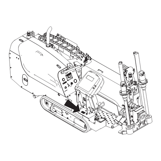
JT5 Operator’s Manual Overview - 4 Unit Components Unit Components 1. Anchoring system 5. Tracks 2. Operator’s station 6. Spindle 3. Carriage 7. Drill frame 4. Stabilizer 8. Wrench ®... -
Page 6: Operator Orientation
JT5 Operator’s Manual Overview - 5 Operator Orientation Operator Orientation IMPORTANT: Top view of unit is shown. 1. Front of unit 2. Right side of unit 3. Rear of unit 4. Left side of unit About This Manual This manual contains information for the proper use of this machine. See the beige Operation Overview pages for basic operating procedures. - Page 7 JT5 Operator’s Manual Overview - 6 ®...
-
Page 8: Foreword
If you sell your equipment, be sure to give this manual to the new owner. If you need a replacement copy, contact your Ditch Witch dealer. If you need assistance in locating a dealer, visit our website at www.ditchwitch.com or write to the following address: The Charles Machine Works, Inc. - Page 9 Copyright 2011, 2014 by The Charles Machine Works, Inc. , Ditch Witch, CMW, Jet Trac, Fluid Miser, Power Pipe, Pierce Airrow, and The Underground, are registered trademarks of The Charles Machine Works, Inc. This product is covered by one or more of the following patents: U.S.
- Page 10 JT5 Operator’s Manual Contents - 9 Contents Overview machine serial number, information about the type of work this machine is designed to perform, basic machine components, and how to use this manual Foreword part number, revision level, and publication date of this manual, and factory contact...
- Page 11 JT5 Operator’s Manual Contents - 10 Specifications machine specifications including weights, measurements, power ratings, and fluid capacities Support the warranty policy for this machine, and procedures for obtaining warranty consideration and training Service Record a record of major service performed on the machine...
-
Page 12: Safety
JT5 Operator’s Manual Safety - 11 Safety Chapter Contents Guidelines ....... . 12 Emergency Procedures . -
Page 13: Guidelines
Use equipment carefully. Stop operation and investigate anything that does not look or feel right. • Do not operate unit where flammable gas may be present. • Contact your Ditch Witch dealer if you have any question about operation, maintenance, or equipment use. • Complete the equipment checklist located at www.ditchwitch.com/resources/safety. -
Page 14: Emergency Procedures
JT5 Operator’s Manual Safety - 13 Emergency Procedures Emergency Procedures Jobsite hazards could cause death or serious injury. Use correct equipment and work methods. Use and maintain proper safety equipment. 274-050 Before operating any equipment, review emergency procedures and check that all safety precautions have been taken. -
Page 15: If An Electric Line Is Damaged
JT5 Operator’s Manual Safety - 14 Emergency Procedures If an Electric Line is Damaged If you suspect an electric line has been damaged and you are on drilling unit or bonded equipment, DO NOT MOVE. Remain on drilling machine and take the following actions. The order and degree of action will depend on the situation. -
Page 16: If A Gas Line Is Damaged
JT5 Operator’s Manual Safety - 15 Emergency Procedures If a Gas Line is Damaged Fire or explosion possible. Fumes could ignite and cause burns. No smoking, no flame, no spark. 275-419 (2P) Explosion possible. Serious injury or equipment damage could occur. -
Page 17: If A Fiber Optic Cable Is Damaged
JT5 Operator’s Manual Safety - 16 Emergency Procedures If a Fiber Optic Cable is Damaged Do not look into cut ends of fiber optic or unidentified cable. Vision damage can occur. Contact utility company. If Machine Catches on Fire Perform emergency shutdown procedure and then take the following actions. The order and degree of action will depend on the situation. -
Page 18: Safety Alert Classifications
JT5 Operator’s Manual Safety - 17 Safety Alert Classifications Safety Alert Classifications These classifications and the icons defined on the following pages work together to alert you to situations which could be harmful to you, jobsite bystanders or your equipment. When you see these words and icons in the book or on the machine, carefully read and follow all instructions. - Page 19 JT5 Operator’s Manual Safety - 18 Machine Safety Alerts Machine Safety Alerts ‘ Moving parts could cut off hand or foot. Stay away. 275-184, 273-437, Electric shock will cause death or serious injury. Stay away. 274-049 Fire or explosion possible. Do not use starter fluid.
- Page 20 JT5 Operator’s Manual Safety - 19 Machine Safety Alerts Hot parts may cause burns. Do not touch until cool or wear gloves. 275-355 (2-P), 273-423 (2-P) Read operator’s manual. Know how to use all controls. Your safety is at stake.
- Page 21 JT5 Operator’s Manual Safety - 20 Machine Safety Alerts ®...
-
Page 22: Controls
JT5 Operator’s Manual Controls - 21 Controls Chapter Contents Set-Up Console ......22 Anchor Console ......24 Operator’s Station . -
Page 23: Set-Up Console
JT5 Operator’s Manual Controls - 22 Set-up Console Set-up Console 1. Engine stop button 3. Left track control 2. Stabilizer and frame tilt control 4. Right track control Item Description Notes 1. Engine stop button To stop engine, press. IMPORTANT: •... - Page 24 JT5 Operator’s Manual Controls - 23 Set-up Console Item Description Notes 2. Stabilizer and frame tilt To raise stabilizer and Note: Stabilizer control lowers the control decrease frame tilt, pull. front of the drill frame along with the stabilizer. To lower stabilizer and increase frame tilt, push.
-
Page 25: Anchor Console
JT5 Operator’s Manual Controls - 24 Anchor Console Anchor Console 1. Left rotation control 3. Right rotation control 2. Left thrust control 4. Right thrust control Item Description Notes 1. Left rotation control To drive anchor, push down. IMPORTANT: Stand on platform when operating anchor controls. - Page 26 JT5 Operator’s Manual Controls - 25 Anchor Console Item Description Notes 2. Left thrust control To move anchor down, push IMPORTANT: Stand on platform when down. operating anchor controls. To move anchor up, pull up. 3. Right rotation control To drive anchor, push down.
-
Page 27: Operator's Station
JT5 Operator’s Manual Controls - 26 Operator’s Station Operator’s Station Gauges and Indicators 1. Hydraulic fluid sight glass 4. Engine oil pressure indicator 2. Hourmeter 5. Engine temperature indicator 3. Cold start wait (glow plug) indicator 6. Drilling fluid pressure gauge... - Page 28 JT5 Operator’s Manual Controls - 27 Operator’s Station Item Description Notes 2. Hourmeter Displays engine operating Use engine operating times to time. schedule service. 3. Cold start wait indicator Lights when intake air pre- See “Start Unit” on page 58.
- Page 29 JT5 Operator’s Manual Controls - 28 Operator’s Station Item Description Notes 6. Drilling fluid pressure Displays drilling fluid pressure If pressure is too high, check if nozzle gauge supplied by drilling fluid is plugged. pump. • Yellow: low pressure •...
-
Page 30: Controls
JT5 Operator’s Manual Controls - 29 Operator’s Station Controls 1. Ignition switch 5. Wrench control 2. Engine throttle control 6. Pipe lubricator control 3. Fluid flow control 7. Auxiliary outlet 4. Carriage control Item Description Notes 1. Ignition switch To start engine, insert key and turn clockwise. - Page 31 JT5 Operator’s Manual Controls - 30 Operator’s Station Item Description Notes 2. Engine throttle control To increase engine speed, push up. To decrease engine speed, pull down. 3. Fluid flow control To increase flow, turn counterclockwise. To decrease flow, turn clockwise.
- Page 32 JT5 Operator’s Manual Controls - 31 Operator’s Station Item Description Notes 7. Auxiliary outlet Provides power for other Power output is 12V, 5A. equipment. ®...
-
Page 33: Engine Compartment
JT5 Operator’s Manual Controls - 32 Engine Compartment Engine Compartment 1. Air filter service indicator 3. Battery disconnect switch 2. DrillLok™/tracker control switch Item Description Notes 1. Air filter service Indicates when to change air indicator filter. Press button to reset indicator after changing filter. - Page 34 JT5 Operator’s Manual Controls - 33 Engine Compartment Item Description Notes 2. DrillLok™/tracker To allow tracker operator to IMPORTANT: Remove key and keep control key stop thrust and rotation, move in tracker operator’s possession. key to enable position (up). To override DrillLok/tracker control mode, move key to override position (right).
-
Page 35: Esid
JT5 Operator’s Manual Controls - 34 ESID ESID j07om042h.eps 1. Alphanumeric display 5. Current problem indicator 2. Strike indicator 6. OK indicator 3. Alarm interrupt button 7. Electrical power supply indicator 4. Voltage problem indicator 8. Self test button Item... - Page 36 JT5 Operator’s Manual Controls - 35 ESID Item Description Notes 2. Strike indicator Red lights come on as values NOTICE: The ESID does not indicate in display increase. proximity to electric lines. System will activate only when voltage and/or Light in triangle represents...
- Page 37 JT5 Operator’s Manual Controls - 36 ESID Item Description Notes 6. OK indicator Green light means system self test detected no problems. Strike system is ready to operate. 7. Electrical power supply Green light means control indicator box has sufficient electrical power for operation.
-
Page 38: Operation Overview
JT5 Operator’s Manual Operation Overview - 37 Operation Overview Chapter Contents Planning........38 Setting Up at Jobsite . -
Page 39: Planning
JT5 Operator’s Manual Operation Overview - 38 Planning Planning 1. Gather information about jobsite. See page 43. 2. Inspect jobsite. See page 44. 3. Classify jobsite. See page 46. 4. Plan bore path. See page 49. 5. Check supplies and prepare equipment. See page 55. -
Page 40: Drilling
• Keep all bends as gradual as possible. ® • Drilling fluid quality is a key factor in backreaming success. Contact your Ditch Witch dealer for information on testing water, selecting additives, and mixing drilling fluid. • Backreaming requires more fluid than drilling. Make sure enough fluid is used. -
Page 41: Leaving Jobsite
JT5 Operator’s Manual Operation Overview - 40 Leaving Jobsite Leaving Jobsite 1. Remove downhole tools. See page 83. 2. Remove anchors. See page 88. 3. Rinse unit and downhole tools. See page 116. 4. Disassemble strike system and disconnect from fluid system. See page 117. -
Page 42: Prepare
Manual Prepare - 41 Prepare Chapter Contents Gather Information ......43 • Review Job Plan ......... . 43 •... -
Page 43: Prepare
Manual Prepare - 42 Prepare Jobsite ......54 • Mark Bore Path ......... . . 54 •... -
Page 44: Gather Information
Manual Prepare - 43 Gather Information Gather Information A successful job begins before the bore. The first step in planning is reviewing information already available about the job and jobsite. Review Job Plan Review blueprints or other plans and make sure you have taken bore enlargement during backreaming and pullback into account. -
Page 45: Inspect Site
Manual Prepare - 44 Inspect Site Inspect Site Inspect jobsite before transporting equipment. Check for the following: • overall grade or slope • changes in elevation such as hills or open trenches • obstacles such as buildings, railroad crossings, or streams •... -
Page 46: Select Start And End Points
Manual Prepare - 45 Inspect Site Select Start and End Points Select one end to use as a starting point. Consider the following when selecting a starting point: Slope Fluid system should be parked on a level site. Consider how slope will affect drilling unit setup, bending pipe, and fluid flow out of hole. -
Page 47: Classify Jobsite
Manual Prepare - 46 Classify Jobsite Classify Jobsite Inspect Jobsite • Follow U.S. Department of Labor regulations on excavating and trenching (Part 1926, Subpart P) and other similar regulations. • Contact your local One-Call (811 in USA) or the One-Call referral number (888-258-0808 in USA and Canada) to have underground utilities located before digging. -
Page 48: Apply Precautions
Manual Prepare - 47 Classify Jobsite Apply Precautions Once classified, precautions appropriate for jobsite must be taken. Electric Jobsite Precautions Electric shock will cause death or serious injury. Stay away. In addition to using a directional drilling system with an electric strike system, use one or both of these methods. - Page 49 Manual Prepare - 48 Classify Jobsite Crystalline Silica (Quartz) Dust Precautions Use breathing protection when exposed to silica dust. 270-4952 To help avoid injury: Cutting, drilling, or working materials such as concrete, sand, or rock containing quartz may result in exposure to silica dust. Use water spray or other means to control dust. If workers are exposed to dust they must wear appropriate breathing protection.
-
Page 50: Plan Bore Path
Plan Bore Path ® Plan the bore path, from entry to end, before drilling begins. The Ditch Witch Trac Management System Plus is available for planning your bore path. This special software can be run in the field using a laptop ®... -
Page 51: Recommended Bend Limits
IMPORTANT: Consider recommended bend limits during any bend, not just during bore entry. Pipe Pitch Ditch Witch drill pipe is tested to bend at a maximum percent pitch. For JT5 drill pipe, make sure pitch (A) changes no more than 7% over the full length of each pipe. - Page 52 Manual Prepare - 51 Plan Bore Path Pipe-By-Pipe Bend Limits Pipe Forward (B) Deflection (A) Pipe Forward (B) Deflection (A) 4’ 11" (1.5 m) 0’ 2" (.05 m) 55’ 5" (16.9 m) 27’ 3" (8.3 m) 9’ 10" (3.0 m) 0’...
-
Page 53: Entry Pitch
Manual Prepare - 52 Plan Bore Path Entry Pitch Entry pitch is the slope of the drill frame compared with the slope of the ground. Determine entry pitch one of two ways: 1. With Pitch Beacon • Lay pitch beacon on the ground and read pitch. -
Page 54: Minimum Depth
Manual Prepare - 53 Plan Bore Path Minimum Depth Because you must bend pipe gradually, entry pitch and bend limits determine how deep the pipe will be when it becomes horizontal. This is called the minimum depth. • To reduce minimum depth (D1), reduce entry pitch. -
Page 55: Prepare Jobsite
Manual Prepare - 54 Prepare Jobsite Prepare Jobsite Jobsite hazards could cause death or serious injury. Use correct equipment and work methods. Use and maintain proper safety equipment. 274-050; 274-724 (2P) To help avoid injury: • If jobsite classification is in question or if the possibility of unmarked electric utilities exists, classify jobsite as electric. -
Page 56: Check Supplies And Prepare Equipment
Manual Prepare - 55 Check Supplies and Prepare Equipment Check Supplies and Prepare Equipment Check Supplies • receiver/transmitter or tracker with spare batteries • extra batteries for DrillLok™ remote, if equipped • beacons with new and spare batteries • two-way radios with new and spare batteries •... -
Page 57: Prepare Equipment
Manual Prepare - 56 Check Supplies and Prepare Equipment Prepare Equipment Fluid Levels • fuel (Use low sulfur or ultra low sulfur fuel only.) • hydraulic fluid • engine coolant • battery charge • engine oil Condition and Function • filters (air, oil, hydraulic) •... -
Page 58: Drive
JT5 Operator’s Manual Drive - 57 Drive Chapter Contents Start Unit ....... . . 58 Steer Unit . - Page 59 JT5 Operator’s Manual Drive - 58 Start Unit Start Unit 1. Insert key. 2. Turn key clockwise. When the ambient temperature is below 32°F (0°C), use the cold start procedure to activate glow plugs. • Turn key to ON position. Glow plugs will activate.
- Page 60 JT5 Operator’s Manual Drive - 59 Shut Down Unit Shut Down Unit 1. Stop track movement. 2. Lower drill frame and stabilizer to the ground. IMPORTANT: If frame and stabilizer cannot be lowered, use cylinder locks or other suitable material to block the tracks. Remove cylinder locks or chocks before driving unit.
- Page 61 JT5 Operator’s Manual Drive - 60 Shut Down Unit ®...
-
Page 62: Transport
JT5 Operator’s Manual Transport - 61 Transport Chapter Contents Lift ........62 Haul . -
Page 63: Lift
JT5 Operator’s Manual Transport - 62 Lift Lift This machine is not configured for lifting. If the machine must be lifted, load machine into a container or onto a platform appropriate for lifting. See “Specifications” on page 145 for weight of machine. -
Page 64: Tie Down
JT5 Operator’s Manual Transport - 63 Haul Tie Down Points Tiedown points are identified by tiedown decals. Securing to trailer at other points is unsafe and can damage machinery. Procedure Read operator’s manual. Know how to use all controls. Your safety is at stake. -
Page 65: Unload
JT5 Operator’s Manual Transport - 64 Haul Unload Crushing weight. If load falls or moves it could kill or crush you. Use proper procedures and equipment or stay away. To help avoid injury: • Load and unload trailer on level ground. -
Page 66: Tow
JT5 Operator’s Manual Transport - 65 Under normal conditions, drilling unit should not be towed. If unit breaks down and towing is necessary: • Attach chains to indicated tow points facing towing vehicle. • Disengage track hydraulics. • Tow for short distances at less than 1 mph (1.6 km/h). - Page 67 JT5 Operator’s Manual Transport - 66 Read operator’s manual. Know how to use all controls. Your safety is at stake. 273-475 To help avoid injury: Do not use tiedown points (D-rings) for towing or lifting. Loop chain through tow points on left and right side of unit (shown) and pull straight forward.
-
Page 68: Conduct A Bore
JT5 Operator’s Manual Conduct a Bore - 67 Conduct a Bore Chapter Contents Position Equipment ......69 Connect Fluid System . - Page 69 JT5 Operator’s Manual Conduct a Bore - 68 Record Bore Path ......78 Surface Drill Head ......79 Assemble Backream String .
-
Page 70: Position Equipment
JT5 Operator’s Manual Conduct a Bore - 69 Position Equipment Position Equipment 1. Review bore plan and select drilling unit position and fluid unit position. See “Select Start and End Points” on page 47. 2. Move equipment into selected positions. -
Page 71: Prime Drilling Fluid Pump
JT5 Operator’s Manual Conduct a Bore - 70 Prime Drilling Fluid Pump Prime Drilling Fluid Pump Read operator’s manual. Know how to use all controls. Your safety is at stake. 273-475 To help avoid injury: Failure to prime the drilling fluid pump will cause flow fluctuations, which will make it difficult to control the washwand. -
Page 72: Operate Carriage Control
JT5 Operator’s Manual Conduct a Bore - 71 Operate Carriage Control Operate Carriage Control The thrust/rotation control has eight positions which allow the four basic functions to be combined. The chart below summarizes functions that occur when control is put at a combined position. Operator must be in seat for control to function. - Page 73 JT5 Operator’s Manual Conduct a Bore - 72 Clamp Pipe Clamp Pipe Turning shaft can kill you or crush arm or leg. Stay away. To help avoid injury: Clamping anywhere else on the pipe will weaken the pipe. Pipe can later break, even when operating under normal loads.
-
Page 74: Assemble Drill String
1. Select nozzles and bit. IMPORTANT: A variety of nozzles and bits are available to suit your particular job conditions. See ® “Downhole Tools” on page 102 for more information, or contact your Ditch Witch dealer. 2. Insert nozzle (2) into beacon housing. -
Page 75: Attach Transition Sub
JT5 Operator’s Manual Conduct a Bore - 74 Assemble Drill String Attach Transition Sub Use either machine torque or quick wrench to attach transition sub. • Attach transition sub (6) directly to beacon housing (1), or • Attach transition sub (5) to EZ-Connect adaptor (4). -
Page 76: Drill First Pipe
JT5 Operator’s Manual Conduct a Bore - 75 Drill First Pipe Drill First Pipe Turning shaft can kill you or crush arm or leg. Stay away. To help avoid injury: • Keep everyone at least 10’ (3 m) away from turning drill string. -
Page 77: Add Pipe
JT5 Operator’s Manual Conduct a Bore - 76 Add Pipe Add Pipe 1. Set engine throttle to full speed. 2. Clamp pipe joint. See “Clamp Pipe” on page 72. 3. Locate drill head. 4. Engage front wrench until pipe is clamped and pressure develops. -
Page 78: Correct Direction
Correcting direction is a skill operators gain with experience and knowledge of equipment and soil conditions. These instructions cover only basic procedures. For information about specific equipment or ® jobsites, contact your Ditch Witch dealer. To track progress and make corrections, one crew member locates the drill head and sends instructions to the operator. -
Page 79: Drill Head Position
The display can store jobs in its memory or the ® system can be run in the field using a laptop computer equipped with the Windows 95 or higher operating ® system. See your Ditch Witch dealer for details. ®... -
Page 80: Surface Drill Head
JT5 Operator’s Manual Conduct a Bore - 79 Surface Drill Head Surface Drill Head Moving tools will kill or injure. Never use pipe wrenches on drill string. Turning shaft will kill you or crush arm or leg. Stay away. To help avoid injury: •... -
Page 81: Assemble Backream String
JT5 Operator’s Manual Conduct a Bore - 80 Assemble Backream String Assemble Backream String Sometimes it is necessary to enlarge the pilot hole to accommodate larger product. As a general rule, the final hole should be 1.5 times larger than the diameter of the product being installed. The number of passes needed depends on soil conditions. - Page 82 JT5 Operator’s Manual Conduct a Bore - 81 Assemble Backream String 1. Select backreaming devices. See “Backreamers” on page 104. 2. Determine fluid rate requirements and install appropriate nozzles to provide sufficient flow. See “Backream Fluid Requirements” on page 105 and “Nozzles” on page 102.
-
Page 83: Remove Pipe
JT5 Operator’s Manual Conduct a Bore - 82 Remove Pipe Remove Pipe NOTICE: If engine is shut off during backreaming, drill pipe clamped by wrenches but not connected to saver sub can be pulled downhole as vise wrenches loosen. 1. Stop carriage when pipes are aligned in wrenches. -
Page 84: Remove Pullback Device
JT5 Operator’s Manual Conduct a Bore - 83 Remove Pullback Device Remove Pullback Device The pullback device can be removed when the last pipe is on the frame. It can also be removed when a target pit along the bore path has been reached. Remaining pipe is then pulled back and removed. - Page 85 JT5 Operator’s Manual Conduct a Bore - 84 Remove Pullback Device ®...
-
Page 86: Systems And Equipment
JT5 Operator’s Manual Systems and Equipment - 85 Systems and Equipment Chapter Contents Anchor System ......87 •... - Page 87 JT5 Operator’s Manual Systems and Equipment - 86 Drill Pipe ....... . 109 •...
-
Page 88: Anchor System
JT5 Operator’s Manual Systems and Equipment - 87 Anchor System Anchor System Crushing weight. If load falls or moves, it could kill or crush you. Use proper procedures and equipment or stay away. To help avoid injury: • Stand on operator platform. -
Page 89: Drive Anchor
JT5 Operator’s Manual Systems and Equipment - 88 Anchor System Drive Anchors IMPORTANT: Carefully time anchor rotation with anchor movement. Properly driven anchors should thread into soil and should not auger up soil. 1. Use anchor rotation and thrust controls to drive anchor into ground. -
Page 90: Electric Strike System
JT5 Operator’s Manual Systems and Equipment - 89 Electric Strike System Electric Strike System Any time you drill in an electric jobsite, electric strike system must be properly set up, tested, and used. You must wear protective boots and gloves meeting the following standards: •... -
Page 91: Assemble Voltage Detector
JT5 Operator’s Manual Systems and Equipment - 90 Electric Strike System Assemble Voltage Detector 1. Drive voltage stake into ground at least 6’ (2 m) away from any part of system. 2. Clip voltage limiter to voltage stake. Test Strike System If system fails any part of this test, see “ESID Diagnostic Codes”... -
Page 92: Troubleshoot Strike System
JT5 Operator’s Manual Systems and Equipment - 91 Electric Strike System ESID Diagnostic Codes When strike system detects a problem, an error code will be displayed. Anytime this happens, press self test button to retest. If error code is still displayed and does not appear in this chart, have control module checked or replaced. - Page 93 JT5 Operator’s Manual Systems and Equipment - 92 Electric Strike System Troubleshoot Strike System In addition to self-test diagnostic codes, other problem situations and their possible causes and solutions are listed in the chart below. Problem Possible cause Possible solution...
- Page 94 JT5 Operator’s Manual Systems and Equipment - 93 Electric Strike System Problem Possible cause Possible solution Strobe light on drilling unit Improper connections with Check connections and wiring does not work during total control module harness test Defective strobe light 1.
-
Page 95: Use Electric Strike Simulator
JT5 Operator’s Manual Systems and Equipment - 94 Electric Strike System Problem Possible cause Possible solution EV2 code displays and Improper connections with Check cable connection on control voltage problem indicator is control module module Defective voltage limiter Have voltage limiter checked or... - Page 96 JT5 Operator’s Manual Systems and Equipment - 95 Electric Strike System To test for current at strike levels: 1. Put two or three loops through current transformer. 2. Follow steps above to test. 3. Display should show the following: •...
-
Page 97: Drilling Fluid
Con Det water-soluble cleaning solution (p/n 259-810) Guidelines Match drilling fluid to soil type. This chart is meant as a guideline only. See your local Ditch Witch dealer for soil conditions and drilling fluid recommendations for your area. Soil type... -
Page 98: Bentonite
JT5 Operator’s Manual Systems and Equipment - 97 Drilling Fluid Bentonite Bentonite is a dry powder. When properly mixed with water, it forms a thin cake on bore walls, lubricating the bore, keeping it open, and holding fluid in the bore. -
Page 99: Basic Fluid Recipes
JT5 Operator’s Manual Systems and Equipment - 98 Drilling Fluid Basic Fluid Recipes Soil type Mixture/100 gal (378 L) of water Notes fine sand ® 35 lb (16 kg) Bore-Gel coarse sand 35 lb (16 kg) Bore-Gel ® Add .5 lb (225 g) of Quik-Trol ®... -
Page 100: Drilling Fluid Requirements
JT5 Operator’s Manual Systems and Equipment - 99 Drilling Fluid Drilling Fluid Requirements 1. Determine drilling conditions and choose appropriate drilling fluid mix. 2. Estimate amount of supplies needed and check availability. • Drilling fluid • Water supply. If more water than can be carried with the unit will be needed, arrange to transport additional water. -
Page 101: Funnel Viscosity
JT5 Operator’s Manual Systems and Equipment - 100 Drilling Fluid Funnel Viscosity Viscosity is the measure of internal resistance of a fluid to flow; the greater the resistance, the higher the viscosity. Viscosity of drilling fluids must be controlled. To determine viscosity, you will need a Marsh funnel (p/n 259-267) and a measuring cup, available from ®... -
Page 102: Drilllok™/Tracker Control
JT5 Operator’s Manual Systems and Equipment - 101 DrillLok™/Tracker Control DrillLok™/Tracker Control Overview Rotating shaft will cause death or serious injury. Stay away. To help avoid injury: • Use DrillLok/tracker control any time you change downhole tools or during other times when the drill string is exposed. -
Page 103: Downhole Tools
Bits Selection These charts are meant as a guideline only. No one bit works well in all conditions. See your Ditch Witch dealer for soil conditions and bit recommendations for your area. • 1 = best •... -
Page 104: Beacon Housings
JT5 Operator’s Manual Systems and Equipment - 103 Downhole Tools Soil Description sandy soil sugar sand, blow sand, or other soils where sand is the predominant component soft soil sandy loam medium soil loams, loamy clays hard soil packed clays, gumbo, all compacted soils... -
Page 105: Backreamers
A backreamer enlarges the hole as pipe is pulled back through the bore. No one backreamer works well in ® all conditions. These charts are meant as a guideline only. See your local Ditch Witch dealer for soil conditions and backreamer recommendations for your area. -
Page 106: Backream Fluid Requirements
Metric 18 L x .5 m/min = 9 L for each minute of each minute of backreaming. backreaming ® IMPORTANT: After you have determined how much fluid you will need, see your Ditch Witch dealer for nozzle recommendations. ®... - Page 107 JT5 Operator’s Manual Systems and Equipment - 106 Downhole Tools Backream Fluid Requirements Backreamer/product Gal/ft Backreamer/product Gal/ft diameter diameter .5 in 13 mm 0.01 0.13 13.5 in 343 mm 7.44 92.35 1 in 25 mm 0.04 0.51 14 in 356 mm 8.00...
-
Page 108: Quick Wrench
JT5 Operator’s Manual Systems and Equipment - 107 Quick Wrench Quick Wrench To attach or remove downhole tools, use quick wrench to join or break the joint. Moving tools will kill or injure. Never use pipe wrenches on drill string. - Page 109 JT5 Operator’s Manual Systems and Equipment - 108 Quick Wrench To Join 1. Scribe straight line across joint on both sides of separating line (A). 2. Scribe second line (B) on moveable side of joint in the opposite direction of tightening action .25” (6 mm) away from first line.
- Page 110 JT5 Operator’s Manual Systems and Equipment - 109 Drill Pipe Drill Pipe Perform Regular Drill Pipe Care Precondition New Pipe Repeat this procedure three times for each piece of pipe before it is used the first time: 1. Hand-lubricate entire surface of threads and shoulders of both ends of pipe with copper base tool joint compound.
- Page 111 JT5 Operator’s Manual Systems and Equipment - 110 Drill Pipe Use Caps and Plugs Before transporting in dusty conditions or prolonged storage, install caps and plugs to male and female ends of pipe and to saver sub. Replace Worn Saver Sub Because each pipe comes in contact with the saver sub, check saver sub regularly for wear.
- Page 112 JT5 Operator’s Manual Systems and Equipment - 111 Drill Pipe Use Drill Pipe Correctly Align the Joints Always carefully align the male and female ends of pipe before screwing them together. Poor alignment can damage the threads and destroy the usefulness of the joint.
- Page 113 JT5 Operator’s Manual Systems and Equipment - 112 Drill Pipe Make Up and Break Out Joints Correctly • Make up and break out joints slowly. Do not ram pipes together during makeup or force them apart during breakout. Carefully time rotation with carriage travel speed, and always connect and disconnect joints slowly and deliberately.
-
Page 114: Complete The Job
JT5 Operator’s Manual Complete the Job - 113 Complete the Job Chapter Contents Antifreeze Drilling Unit ....114 • Add Antifreeze ......... . .114 •... -
Page 115: Antifreeze Drilling Unit
JT5 Operator’s Manual Complete the Job - 114 Antifreeze Drilling Unit Antifreeze Drilling Unit Your drilling unit can be left overnight in freezing conditions by circulating a polyproplyene-based antifreeze (p/n 265-644) through optional antifreeze system before shutdown. Add Antifreeze Without optional antifreeze kit: 1. -
Page 116: Reclaim Antifreeze
JT5 Operator’s Manual Complete the Job - 115 Antifreeze Drilling Unit Reclaim Antifreeze 1. Connect remote fluid system. See page 69. 2. Turn on remote fluid system engine and open valves to allow fluid flow. 3. Start drilling unit and run at low throttle. -
Page 117: Rinse Equipment
JT5 Operator’s Manual Complete the Job - 116 Rinse Equipment Rinse Equipment Using Optional Washwand Connect the washwand at quick connect at rear of unit. Close valve (shown) to shut off flow to spindle. IMPORTANT: • Never use high flow when using wash wand. -
Page 118: Disconnect
JT5 Operator’s Manual Complete the Job - 117 Disconnect Disconnect Disconnect and store the following hoses and cables (if used): • electric strike system voltage stake • fluid hose Stow Tools Make sure all quick wrenches, bits, pullback devices, and other tools are loaded and properly secured on trailer. - Page 119 JT5 Operator’s Manual Complete the Job - 118 Stow Tools ®...
-
Page 120: Service
JT5 Operator’s Manual Service - 119 Service Chapter Contents Service Precautions ..... . . 120 Recommended Lubricants/Service Key ..122 Startup/10 Hour . - Page 121 JT5 Operator’s Manual Service - 120 Service Precautions Service Precautions Read operator’s manual. Know how to use all controls. Your safety is at stake. 273-475 To help avoid injury: • Unless otherwise instructed, all service should be performed with engine off.
- Page 122 JT5 Operator’s Manual Service - 121 Service Precautions Working Under Drilling Unit Crushing weight could cause death or serious injury. Use proper procedures and equipment or stay away. Before working under area of drilling unit supported by a stabilizer, make sure drilling unit is parked on hard surface.
- Page 123 Service intervals listed are for minimum requirements. In extreme conditions, service machine more frequently. Use only genuine Ditch Witch parts, filters, approved lubricants, TJC, and approved coolants to maintain warranty. Fill to capacities listed in “Specifications” on page 145.
- Page 124 In certain markets, higher blends may be used if certain steps are taken. Extra attention is needed when using biodiesel, especially when operating in cold weather or ® storing fuel. Contact your Ditch Witch dealer or the engine manufacturer for more information. ®...
- Page 125 JT5 Operator’s Manual Service - 124 Startup/10 Hour Startup/10 Hour Location Task Notes DRILLING Check engine air filter service indicator UNIT Check engine oil level Check hydraulic hoses Check hydraulic fluid level Check pipe auto lubricator spray nozzle optional equipment...
- Page 126 JT5 Operator’s Manual Service - 125 Startup/10 Hour Check Engine Oil Level While engine oil is warm, move carriage to front of drill frame and check oil level at dipstick (1) before startup and every 10 hours of operation. Add DEO at fill tube (2) as necessary to keep oil level at highest line on dipstick.
- Page 127 JT5 Operator’s Manual Service - 126 Startup/10 Hour Check Hydraulic Hoses Pressurized fluid or air could pierce skin and cause severe injury. Refer to operator’s manual for proper use. 270-6035 To help avoid injury: Escaping pressurized fluid can cause injury or pierce skin and poison.
- Page 128 Clean as needed. ® NOTICE: Ditch Witch tool joint compound is specially formulated to work with Ditch Witch pipe lubrication system. Use of other tool joint compounds will clog system. See “Recommended Lubricants/Service Key” on page 122 for more information.
- Page 129 JT5 Operator’s Manual Service - 128 Startup/10 Hour Check Coolant Level Check coolant level before startup and every 10 hours of operation. When machine is cold, add coolant as needed to maintain between LOW and FULL indicators shown on overflow bottle.
- Page 130 JT5 Operator’s Manual Service - 129 50 Hour 50 Hour Location Task Notes DRILLING Change engine oil and filter Initial service, DEO UNIT Change drilling fluid pump oil (initial) Clean drilling fluid pump strainer Check radiator Change hydraulic filter Initial service...
- Page 131 JT5 Operator’s Manual Service - 130 50 Hour Change Drilling Fluid Pump Oil (Initial Service) Change fluid pump oil after first 50 hours and every 750 hours thereafter. Drain at plug (2) and add EO at plug (1). Maintain fluid level at fill plug.
- Page 132 JT5 Operator’s Manual Service - 131 50 Hour Change Hydraulic Filter (Initial Service) Change hydraulic filter (shown) after first 50 hours. Check Rotation Gearbox Oil Level Check rotation gearbox oil level every 50 hours. Oil should be visible at plug (2). Add MPL at plug (1) as needed.
- Page 133 JT5 Operator’s Manual Service - 132 50 Hour Check Battery Keep batteries clean and free of corrosion. Apply coat of grease to cable clamps after cleaning. In cold weather, battery loses some starting ability. Closely watch voltmeter for signs of battery discharge.
- Page 134 JT5 Operator’s Manual Service - 133 100 Hour 100 Hour Location Task Notes DRILLING Change fuel filters UNIT Check fan belt tension Drilling Unit Change Fuel Filters Change canister fuel filter (top) and inline fuel filter (bottom) every 100 hours.
- Page 135 JT5 Operator’s Manual Service - 134 150 Hour Check Fan Belt Tension Check pump drive belt tension every 100 hours. 1. Turn off engine and remove key. 2. Apply moderate thumb pressure to top of belt. Belt is properly tensioned when deflection (A) is 1/4-3/8”...
- Page 136 JT5 Operator’s Manual Service - 135 500 Hour 500 Hour Replace Fan Belt Replace fan belt (shown) every 500 hours. To replace 1. Loosen bolts (1, 2) and remove belt. 2. Install new belt and adjust properly. See page 139.
- Page 137 JT5 Operator’s Manual Service - 136 1000 Hour 1000 Hour Location Task Notes DRILLING Change rotation gearbox oil UNIT Change hydraulic fluid and filter Drilling Unit Change Rotation Gearbox Oil Drain oil at gearbox oil drain (3) every 1000 hours.
- Page 138 JT5 Operator’s Manual Service - 137 2000 Hour 2000 Hour Change Engine Coolant Drain cooling system at drain (2). Add approved coolant at fill (1) every two years or 2000 hours. NOTICE: • The use of non-approved coolant may lead to engine damage or premature engine failure and will void engine warranty.
- Page 139 JT5 Operator’s Manual Service - 138 As Needed As Needed Location Task Notes DRILLING Change pipe lubricator TJC tube UNIT Check track tension and condition Adjust fan belt Replace air filter Replace saver sub Check fluid pump check valve Replace carriage slide bars...
- Page 140 As Needed Check Track Tension and Condition Check track tension and condition and adjust or ® replace as needed. See your Ditch Witch dealer for replacement parts. To adjust, turn bolt (1) clockwise to tighten and counterclockwise to loosen. Track tension is correct when dimension A is approximately 2.25”...
- Page 141 As Needed Replace Saver Sub ® Check saver sub and replace as needed. See your Ditch Witch dealer for replacement parts. To replace IMPORTANT: Saver sub must mate up to every drill pipe. Check sub for thread wear. If saver sub threads are more worn than pipe threads, saver sub is damaging the drill pipe.
- Page 142 JT5 Operator’s Manual Service - 141 As Needed Replace Fuses Change fuses (shown) as needed. Refer to decal inside panels to identify fuses. ®...
- Page 143 JT5 Operator’s Manual Service - 142 As Needed Check Battery Check battery as needed. Keep battery clean and terminals free of corrosion. To clean: 1. Turn battery disconnect switch, if equipped, to the off position. 2. Ensure that no ignition sources are near batteries.
- Page 144 JT5 Operator’s Manual Service - 143 As Needed Charge Battery Explosion possible. Serious injury or equipment damage could occur. Follow directions carefully. To help avoid injury: • Use a single 12V maximum source for charging. Do not connect to rapid chargers or dual batteries.
- Page 145 JT5 Operator’s Manual Service - 144 As Needed Charging Procedure (Engine Off) 1. Park service vehicle close to disabled equipment but do not allow vehicles to touch. Engage parking brake in both vehicles. 2. Turn the ignition switch to the OFF position in both vehicles, and turn off all electrical loads. Disconnect the machine controller.
-
Page 146: Specifications
JT5 Operator’s Manual Specifications - 145 Specifications Dimensions U.S. Metric L, overall machine length 120 in 3.1 m W, overall machine width 35.9 in 91.2 cm H, overall machine height 70 in 1.78 m Operating weight w/150’/45.7 m of drill pipe, anchoring system and... - Page 147 JT5 Operator’s Manual Specifications - 146 Operational U.S. Metric Maximum spindle speed 195 rpm 195 rpm Maximum spindle torque 550 ft•lb 746 N•m Thrust force 4100 lb 18.2 kN Pullback force 5000 lb 22.2 kN Carriage travel speed 130 fpm...
-
Page 148: Capacities
JT5 Operator’s Manual Specifications - 147 Drilling Fluid System (Onboard) U.S. Metric Maximum drilling fluid flow 0-5 gpm 0-18.9 L/min Maximum drilling fluid pressure 750 psi 51.7 bar Fluid Capacities U.S. Metric Fuel tank 13 gal 49 L Hydraulic reservoir... - Page 149 JT5 Operator’s Manual Specifications - 148 ®...
-
Page 150: Support
Return damaged parts to dealer for inspection and warranty consideration if in warranty time frame. Order genuine Ditch Witch replacement or repair parts from your authorized Ditch Witch dealer. Use of another manufacturer's parts may void warranty consideration. - Page 151 Subject to the limitation and exclusions herein, free replacement parts will be provided at any authorized Ditch Witch dealership for any Ditch Witch equipment or parts manufactured by The Charles Machine Works, Inc. (CMW) that fail due to a defect in material or workmanship within one (1) year of first commercial use.
-
Page 154: Service Record
JT5 Operator’s Manual Service Record - 153 Service Record Service Performed Date Hours ®... - Page 155 JT5 Operator’s Manual Service Record - 154 Service Performed Date Hours ®...
Need help?
Do you have a question about the JT5 and is the answer not in the manual?
Questions and answers