
Related Manuals for Ormazabal cpg.0-l


Summarization of Contents
1. General Description
1.1. Models
Lists the different models of the cpg.0 switchgear range.
1.2. Standards Applied
Lists standards relevant to the cpg.0 switchgear.
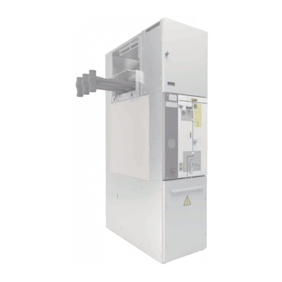
1.3. Main Components
Gas Tank and Busbar Compartment
Describes the insulated gas tank and busbar compartment.
Cable Compartment and Gas Pressure Duct
Describes cable connection and gas exhaust systems.
Incoming Cables, Control, and Driving Mechanism
Details cable entry, control, and operating elements.
1.4. Voltage Presence Indicator
Voltage Presence Indicator Operation
Describes the voltage detection system and its operation.
1.5. Name Plate
Name Plate Details
Explains the information presented on the unit's data plate.
2. Technical Characteristics
2.1. Electrical Characteristics
Lists key electrical parameters and ratings of the switchgear.
2.2. Mechanical Characteristics, Dimensions, and Protection
Covers mechanical aspects, dimensions, weights, and protection grade.
3. Service Conditions
Switchgear Service Conditions
Specifies environmental and operational conditions for use.
4. Handling and Transport
4.1. Transport Conditions
Outlines requirements for safe transportation of the equipment.
4.2. Lifting Means
Describes approved methods for lifting the cubicles.
5. Storage Conditions
Storage Conditions Details
Specifies environmental and handling requirements for storage.
6. Installation
6.1. Unpacking the Equipment
Instructions for safely unpacking the switchgear.
6.2. List of Assembly Materials Supplied
Lists accessories and components provided for installation.
6.3. Cable Trench
Details on preparing and installing the cable trench.
6.4. Minimum Installation Distances
Specifies required clearances around the cubicles.
6.4.1. Interlocks
Explains safety interlock mechanisms and their function.
6.5. Fastening to the Floor
Provides instructions for securing cubicles to the foundation.
6.6. Cubicle Joints
Describes methods for connecting adjacent cubicles.
6.6.1. Fixing Points (cpg.0-v/l/pt/rb)
Details connection points for specific models.
6.6.2. Fixing Points (cpg.0-c)
Details connection points for the bus section circuit breaker.
6.7. Equipment Earthing
Instructions for proper grounding of the equipment.
7. Operations Sequence
7.1. Feeder up to 1250 A
Operation sequences for 1250A feeders.
7.1.1. Circuit Breaker and Switch-Disconnector (cpg.0-v/l)
Operation steps for specific feeder types.
7.1.2. Bus Section Circuit Breaker (cpg.0-c)
Operation sequence for bus section breakers.
7.1.3. Busbar Earthing Switch (cpg.0-pt)
Operation for busbar earthing switches.
7.1.4. Bus Riser (cpg.0-rb)
Operation sequence for bus riser cubicles.
7.2. Feeder up to 2000/2500 A
Operation sequences for 2000/2500A feeders.
7.2.1. Circuit Breaker (cpg.0-v)
Operation steps for higher current circuit breakers.
7.2.2. Bus Section Circuit Breaker (cpg.0-c)
Operation sequence for higher current bus section breakers.
8. Safety Elements
8.1. Interlocks and Padlocking Facilities
Describes safety interlocks and padlocking procedures.
9. Maintenance
Maintenance Procedures
Covers maintenance procedures and recommendations.
10. Spares and Accessories
Spares and Accessories Information
Information on replacement parts and installation.
11. Environmental Information
SF6 Gas and Recyclability
Covers SF6 gas properties and material recycling information.
Need help?
Do you have a question about the cpg.0-l and is the answer not in the manual?
Questions and answers