
Related Manuals for Ormazabal velatia cms.21


Summary of Contents for Ormazabal velatia cms.21
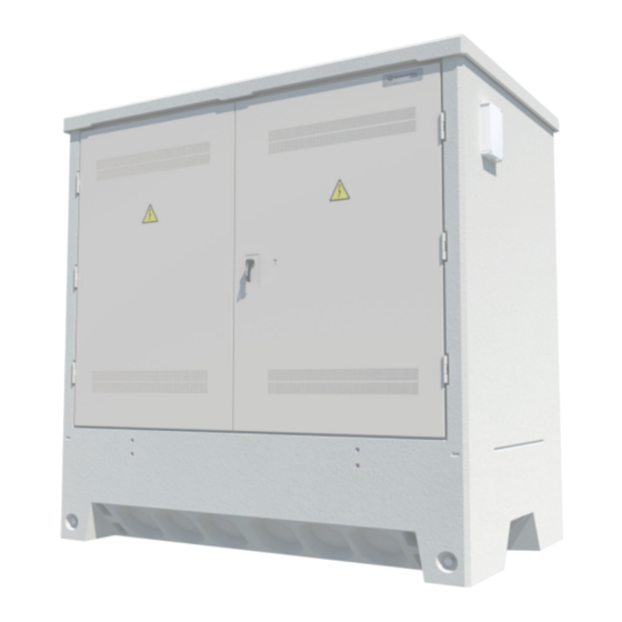
- Page 1 cms.21 Switching and breaking substation General Instructions IG-247-EN, version 01, 19/05/2016...
- Page 2 Therefore, the use of this equipment poses electrical, mechanical and thermal risks. In order to ensure an acceptable level of protection for people and property, and in compliance with applicable environmental recommendations, Ormazabal designs and manufactures its products according to the principle of integrated safety, based on the following criteria: •...
-
Page 3: Table Of Contents
General Instructions Contents cms.21 Contents 1. Description and main characteristics ......4 Components of cms.21..... . . 4 1.1. 1.1.1. Medium-voltage switchgear....5 1.1.2. -
Page 4: Description And Main Characteristics
40.5 kV by Ormazabal. The equipment can optionally include a compact remote control unit for all local and remote control functions (remote control, sectionaliser, fault detection, automatic transfer, etc.). -
Page 5: Medium-Voltage Switchgear
90º and 180º. The right hand door can be supplied with different types of locks (European barrel, Ormazabal lock, etc.), as well as padlocking with eyebolt of up to Ø10 mm. For padlock with eyebolt of up to Ø10 mm... - Page 6 Description and main characteristics General Instructions cms.21 The doors have grilles in the top and bottom sections for The document holder is located on the inside of the right ventilation cms.21. door, with these General Instructions for cms.21 (IG-247) and the General Instructions of the medium-voltage There is an insulating plate on the inside of the door, in the switchgear installed.
-
Page 7: Insulating Operation Platform
General Instructions Description and main characteristics cms.21 1.1.3. Insulating operation platform Optionally, cms.21 can be fitted with an operation platform of insulating material, providing an earth isolated operation surface. Opening out the platform Fold out the platform before carrying out any operation involving the medium-voltage system. -
Page 8: Name Plate
Description and main characteristics General Instructions cms.21 1.1.4. Name plate cms.21 includes a name plate on the inside of the enclosure. The plate indicates at least the following data: Figure 1.8. cms.21 name plate 1.1.5. Lighting Optionally, the cms.21 can be have a lighting fitting with EC marking, using an 11 W energy-saving lamp, magnetically fastened and with cable length suitable for lighting of the work areas and operation of the medium-... -
Page 9: Electrical Characteristics
General Instructions Description and main characteristics cms.21 1.2. Electrical characteristics Characteristic Rated voltage of medium-voltage circuits 24 / 36 / 40.5 Number of phases Rated frequency 50 / 60 Characteristics of earthing circuits: 50 (bare copper conductor) (*) Protection earth collector (disconnection) 50 (bare copper conductor) Doors, plates, metal panels Protection grades... -
Page 10: Mechanical Characteristics
Description and main characteristics General Instructions cms.21 1.3. Mechanical characteristics 1.3.1. Weight cgmcosmos system Voltage 24 kV Medium-voltage configuration Weight switchgear [kg] Total [kg] 4420 4440 4590 4510 4530 4605 4600 Table 1.2. Weights of cms.21 with configurations of the cgmcosmos system cgm.3 system Voltage 36 kV / 40.5 kV... -
Page 11: Dimensions
General Instructions Description and main characteristics cms.21 1.3.2. Dimensions Figure 1.10. Dimensions (in mm) of cm.21 A horizontal line in the exterior walls marks zero installation level. IG-247-EN version 01; 19/05/2016... -
Page 12: Transport
Local regulations will be followed for other aspects of road transport (gauge, maximum authorised weight, etc.). Slings Figure 2.1. Road haulage of cms.21 Check with Ormazabal whenever heights of over 2000 m above sea level are envisaged during road haulage. 2.2.1. Packaging for road haulage cms.21 does not require packaging for road haulage. -
Page 13: Sea Transport
2.3.1. Sea freight packaging Ormazabal recommends using Cortec® VpCI-126® Blue® film (corrosion inhibitor in vapour phase) or similar to seal the cms.21, thus preventing corrosion during sea transport. Placing the enclosure in dehydrated salt is recommended. -
Page 14: Storage
Storage General Instructions cms.21 Storage Placing two cms.21 timber battens measuring 2000 x 150 x 20 mm underneath is recommended. It is also Do not store in corrosive or saline environments. recommended that the floor where the equipment is stored should be uniform, stable and level. -
Page 15: Normal Service Conditions
II, in accordance with Table 1 of Standard IEC 60815. instructions, it will be necessary to define what they are and analyse how they affect the design of the cms.m station. In the case of special conditions of use, contact Ormazabal. IG-247-EN version 01; 19/05/2016... -
Page 16: Installations
Installations General Instructions cms.21 Installations When installing the cms.21 at its location, it is essential to There is an opening between the cover and the body for comply with legislation in force on electrical installations ventilation of the equipment. in electrical grids, in addition to local regulations. The instructions included in this document must be followed Be sure not to block the openings of the cover of the during the electrical installation. -
Page 17: Handling
Figure 5.4. Lifting of cms.21 The attached table indicates the recommended power values for the cranes. Remember that these are reference values and that each case must be confirmed by Ormazabal. Rated power of the crane [t] Weight 15.5 Table 5.1. -
Page 18: Preparing The Location
Figure 5.6. Dimensions (in mm) of the trench 5.4.1. Levelling process As a general rule, Ormazabal recommends having a Levelling the ground is important for correct installation of the cms.21. The following equipment is recommended for 100 mm-thick compacted and levelled layer of sand at... -
Page 19: Cable Transits And Sealing
General Instructions Installations cms.21 5.5. Cable transits and sealing Fitted in the bottom of the enclosure, below ground, the cms.21 has 18 blanked holes for piped conduits of up to Ø200 mm and 8 blanked holes of Ø50 mm for access of the exterior earthing network or other conduits. -
Page 20: Medium-Voltage Cable Connection
General Instructions of the single-phase cables must not exceed 240/16 mm and rated medium-voltage switchgear, supplied with cms.21, in voltage 18/30 kV. For other types of cables, please contact accordance with Standards EN 50180 and EN 50181. Ormazabal. IG-247-EN version 01; 19/05/2016... -
Page 21: Earthing Circuit Connection
General Instructions Installations cms.21 5.6. Earthing circuit connection cms.21 is fitted with an internal protective earthing circuit for easy connection of the different elements to the exterior earthing network implementation. 5.6.1. Protective earthing network cms.21 has a protective earthing disconnection box inside. Optionally, an earth interconnection box can be fitted whenever it is necessary to join the protective earthing Save for specific indication by the customer, the earthing... -
Page 22: Exterior Earthing Network
Installations General Instructions cms.21 5.6.2. Exterior earthing network The installation project must include the implementation The following tightening torque should be observed: of the earthing network (check the standard project of the Tightening torque [Nm] Utility or local regulations in force), along with justification Metric of sizing 8.8 Steel... -
Page 23: Replacing The Medium-Voltage Switchgear
General Instructions Installations cms.21 5.7. Replacing the medium-voltage switchgear Follow the General Instructions supplied with the cms.21 in the document holder for correct handling of the medium- voltage switchgear during replacement (see figure 1.5). 5.7.1. Tools required In order to correctly follow the instructions described below, it is necessary to ensure beforehand that the tools shown in figure 5.14 are available. - Page 24 Installations General Instructions cms.21 3. Release the bolts of the left-hand door to open it. Figure 5.16. Release the bolts of the left-hand door. 4. The doors have an interlocking system at 90º and 180º. To release, pull upward on the rod and open the door. Figure 5.17.
- Page 25 General Instructions Installations cms.21 7. Unscrew the two points which fasten the cover to the body using a 17 wrench (M10 bolt). Figure 5.19. Cover fastening points 8. Remove the four plastic protective caps from the threaded inserts of the cover. Figure 5.20.
- Page 26 Installations General Instructions cms.21 12. Unscrew the attachment points of the switchgear to the rails on the floor of the cms.21. Use the 17 wrench (M10 bolt). Figure 5.23. Unscrew the switchgear fastening points. 13. Extract the switchgear to be replaced. Follow the General Instructions of the medium-voltage switchgear.
-
Page 27: Recommended Sequence Of Operations
General Instructions Recommended sequence of operations cms.21 Recommended sequence of operations All accesses and operations recommended in this It is essential to follow the recommended sequence specification must comply with the procedures indicated of operations set out in the general instructions of the by the utility, along with the electricity safety standards medium-voltage switchgear. -
Page 28: Maintenance
Maintenance General Instructions cms.21 Maintenance Before commissioning, the cms.21 should be cleaned of any dirt which has built up during storage, transport or installation. Regular inspections of the cms.21 are recommended, in line with local regulations. When carrying out maintenance, local electrical safety rules should be followed. - Page 29 General Instructions Notes cms.21 Notes IG-247-EN version 01; 19/05/2016...
- Page 30 Notes General Instructions cms.21 Notes IG-247-EN version 01; 19/05/2016...
- Page 32 Subject to change Ormazabal y Cía. without prior notice. IGORRE For further information, Spain contact Ormazabal. www.ormazabal.com...
Need help?
Do you have a question about the velatia cms.21 and is the answer not in the manual?
Questions and answers