
Subscribe to Our Youtube Channel
Related Manuals for Ormazabal cgm.3 system Series


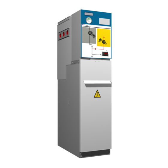
Summary of Contents for Ormazabal cgm.3 system Series
- Page 1 cgm.3 system Fully SF6 gas insulated medium voltage switchgear up to 40.5 kV in accordance with IEC Standards General instructions IG-136-EN, version 10; 23/06/2016...
- Page 2 Therefore, the use of this equipment poses electrical, mechanical and thermal risks. In order to ensure an acceptable level of protection for people and property, and in compliance with applicable environmental recommendations, Ormazabal designs and manufactures its products according to the principle of integrated safety, based on the following criteria: •...
-
Page 3: Table Of Contents
General instructions cgm.3 system Fully SF6 gas insulated medium voltage switchgear up to 40.5 kV in accordance with IEC Standards Contents 1 General description . . . . . . . . . . . . . . . . . . . . . . . . . . . . . . . . . . . . . . . . . . . . . . . . . . . . . . . . . 6 1 .1 Models . - Page 4 General instructions cgm.3 system Fully SF6 gas insulated medium voltage switchgear up to 40.5 kV in accordance with IEC Standards 5 Recommended sequence of operations . . . . . . . . . . . . . . . . . . . . . . . . . . . . . . . . . . . . . . . 34 5 .1 Checking the gas pressure .
- Page 5 General instructions cgm.3 system Fully SF6 gas insulated medium voltage switchgear up to 40.5 kV in accordance with IEC Standards 5 .10 Circuit-breaker function with AV / RAV driving mechanism . . . . . . . . . . . . . . . . . . . . . . . . . . . . . . . . . . . . 58 5.10.1 Mimic diagram .
-
Page 6: General Description
3 system Fully SF6 gas insulated medium voltage switchgear up to 40.5 kV in accordance with IEC Standards 1 General description The cgm.3 system by Ormazabal, designed following the with full SF gas insulation, which can be used to configure... -
Page 7: Standards Applied
General description General Instructions 3 system Fully SF6 gas insulated medium voltage switchgear up to 40.5 kV in accordance with IEC Standards 1.2 Standards applied Standard Description IEC 62271-1 Common specifications for high-voltage switchgear and controlgear standards. IEC 62271-100 High-voltage alternating current circuit-breakers. IEC 62271-102 Alternating current disconnectors and earthing switches. -
Page 8: Gas Tank
General description General Instructions 3 system Fully SF6 gas insulated medium voltage switchgear up to 40.5 kV in accordance with IEC Standards 1.3.1 Gas tank Sealed compartment which houses the busbar and the Thanks to the hermetically-sealed nature of the gas switching and breaking elements, where the insulating tank containing all the medium voltage elements, the medium is SF... -
Page 9: Base
Metallic voltage transformers. Figure 1.3 Cable compartment Gas relief compartment The cgm.3 system by Ormazabal is designed and Optionally, a chimney can be positioned in the constructed to withstand at least the thermal and dynamic rear of the cubicle to redirect the gases to the effects of an arc of 16 kA for 0.5 seconds should a defect... -
Page 10: Name Plate
Gas pressure inside the tank (MPa) Minimum operating gas pressure (MPa) Weight of insulating fluid (g) Year Year of manufacture Minimum working temperature Classification of internal arc In the event of incident, this number should be reported to Ormazabal. IG-136-EN version 10; 23/06/2016... -
Page 11: Characteristics Table
(**) With gas exhaust upwards via the chimney The values set out in this table are general for the cgm.3 system and are only valid once confirmed by Ormazabal. Some cubicle models can withstand partial values. For more detailed information, check the table for each cubicle model in the CA-112 catalogue by Ormazabal. -
Page 12: Dimensions And Weights
1042 In the case of double symmetrical terminal, the Switchgear is an extra 80 mm deep. As an option, there is also available a 595 mm wide model of the cgm.3-v cubicle. Please check with Ormazabal. IG-136-EN version 10; 23/06/2016... -
Page 13: Operating Conditions
Vibrations caused by causes external to the switchgear or by seismic movements Insignificant 1000 m for metering function and non-shielded connectors. For higher installation altitudes, check with Ormazabal. Unless indicated otherwise, It is assumed that there are no specific user requirements. -
Page 14: Handling And Transport
Handling and transport General instructions 3 system Fully SF6 gas insulated medium voltage switchgear up to 40.5 kV in accordance with IEC Standards 2 Handling and transport Important: During transport, the switchgear must be perfectly seated and fixed so that it cannot move about and possibly damage the equipment. - Page 15 Handling and transport General instructions 3 system Fully SF6 gas insulated medium voltage switchgear up to 40.5 kV in accordance with IEC Standards Figure 2.3 Lifting a cgm.3 assembly with 5 functional units. Figure 2.4 Lifting a cgm.3 assembly with a forklift truck. The use of lifting beams is required for cubicle assemblies with control boxes.
-
Page 16: Storage
Storage General instructions 3 system Fully SF6 gas insulated medium voltage switchgear up to 40.5 kV in accordance with IEC Standards 3 Storage If it needs to be stored, the equipment must be placed on After prolonged storage, clean all the insulating parts dry ground or on top of damp-proof insulating material, still carefully before commissioning the equipment. -
Page 17: Installation
On receiving the equipment, check that the goods supplied cable compartment cover. correspond to the order and associated documentation. If this is not the case, contact Ormazabal immediately. The self-adhesive plastic must be removed The disassembly process for the equipment is as follows:... -
Page 18: Minimum Installation Distances
Annex AA of Standard IEC 62271-200. The space required to extend the assembly with an additional cubicle is 250 mm plus the width of the new cubicle For any doubts, please ask Ormazabal. IG-136-EN version 10; 23/06/2016... -
Page 19: Recommended Cable Connection Trench
Installation General instructions 3 system Fully SF6 gas insulated medium voltage switchgear up to 40.5 kV in accordance with IEC Standards 4.4 Recommended cable connection trench Minimum recommended dimensions based on the trench IEC 62271-200. In accordance with the radius of curvature dimensions used in the tests in accordance with Standard of the cables used, these dimensions may vary [10]... - Page 20 Installation General instructions 3 system Fully SF6 gas insulated medium voltage switchgear up to 40.5 kV in accordance with IEC Standards Fuse protection function Front and rear cable input or output (D1) Side cable input or output (D2) Figure 4.5 Dimensions [mm] of the cable trench for cgm.3-p Trench necessary for the fuse protection function Cable data...
- Page 21 Installation General instructions 3 system Fully SF6 gas insulated medium voltage switchgear up to 40.5 kV in accordance with IEC Standards Circuit-breaker function with AV / RAV driving mechanism Front and rear cable input or output (D1) Side cable input or output (D2) Figure 4.6 Dimensions [mm] of the cable trench for cgm.3-v...
-
Page 22: Cubicles With Classification Of Internal Arc Iac Up To 25 Ka - 1 S
Installation General instructions 3 system Fully SF6 gas insulated medium voltage switchgear up to 40.5 kV in accordance with IEC Standards 4.4.2 Cubicles with classification of internal arc IAC up to 25 kA - 1 s Feeder function, busbar rise and cable rise Front and rear cable input or output (D1) - Page 23 Installation General instructions 3 system Fully SF6 gas insulated medium voltage switchgear up to 40.5 kV in accordance with IEC Standards Fuse protection function Front and rear cable input or output (D1) Side cable input or output (D2) Figure 4.8 Dimensions [mm] of the cable trench for cgm.3-p. Trench necessary for the fuse protection function Cable data Minimum depth...
- Page 24 Installation General instructions 3 system Fully SF6 gas insulated medium voltage switchgear up to 40.5 kV in accordance with IEC Standards Circuit-breaker function with AV / RAV driving mechanism Front and rear cable input or output (D1) Side cable input or output (D2) Figure 4.9 Dimensions [mm] of the cable trench for cgm.3-v...
- Page 25 Installation General instructions 3 system Fully SF6 gas insulated medium voltage switchgear up to 40.5 kV in accordance with IEC Standards Metering function Figure 4.10 Dimensions [mm] of the cable trench for cgm.3-m. Trench necessary for the metering function Approximate radius Cable section Cable diameter Depth...
-
Page 26: Fastening To The Floor
Installation General instructions 3 system Fully SF6 gas insulated medium voltage switchgear up to 40.5 kV in accordance with IEC Standards 4.5 Fastening to the floor Before assembling the cubicles, the floor must be carefully The cubicles can be fastened to the floor in two ways: levelled to prevent any deformation which may make it difficult to connect the cubicles to one another. - Page 27 Installation General instructions 3 system Fully SF6 gas insulated medium voltage switchgear up to 40.5 kV in accordance with IEC Standards Anchor the first cubicle to the floor of the installation using M10 bolts at the points prepared in its base. This will prevent displacements or vibrations due to causes such as short-circuiting, flooding, etc.
- Page 28 Installation General instructions 3 system Fully SF6 gas insulated medium voltage switchgear up to 40.5 kV in accordance with IEC Standards Figure 4.18 Detail of anchor points in cgm.3-2lp cubicles 1745 mm high Figure 4.15 Anchoring points in cgm.3. -l, -s, -s-pt, -p, -v, -rb,-rb-pt double cable cubicles of 1745 mm high Figure 4.19 Detail of anchor points in cgm.3-2lp double cable...
-
Page 29: Connecting The Cubicles
4.6 Connecting the cubicles The joining of cubicles must be carried out as indicated in which is supplied with the materials kit used for connecting Ormazabal's RA-163 Spares and Accessories document, cubicles. 4.7 Earthing the switchgear When connecting the general earth collector, follow the Bolt the earth strip between every 2 medium voltage figure below. -
Page 30: Cable Connections
Screened M400TB 35-240 M400TB 18-630 (*) Connectors recommended for the cgm.3 system by Ormazabal. Apart from the list above, CENELEC terminals are also valid. For other values, consult Ormazabal. 4.8.1 Horizontal front connection Close the earthing switch. Remove the cover to access the cable compartment. -
Page 31: Cable Connection In Fuse Protection Function 1400 Mm High
The clamp has two positions, depending on the cable diameter. Specific cable supports should be used for cable diameters above 49 mm. Please check with Ormazabal. Figure 4.25 Horizontal front connection process Put the cable compartment cover back in place. Figure 4.24 Terminal connection detail 4.8.2 Cable connection in fuse protection function 1400 mm high... - Page 32 Installation General instructions 3 system Fully SF6 gas insulated medium voltage switchgear up to 40.5 kV in accordance with IEC Standards Once the cubicle is secured to the floor and the medium Position the four M8 screws with their nuts and fasten voltage cables are connected, carry out the following until tight.
-
Page 33: Assembly And Connection Of Measuring Transformers In Cgm.3-M
For further information on the installation and in tracks installed in the cgm.3-m metering modular cubicle connection of cgm.3-m metering transformers by Ormazabal. by Ormazabal, check the operations manual MO-082 “Installation of transformers and The layout and connection of these transformers busbars in metering cubicles”. -
Page 34: Recommended Sequence Of Operations
Figure 5.1 Pressure gauge 5.2 Voltage presence indicator Ormazabal has two voltage presence indication options: For each of the three phases, the presence of voltage is indicated by intermittent flashing of the indicators. • The ekor.vpis unit for detecting voltage, designed in accordance with Standard IEC 62271-206. -
Page 35: Phase Balance Check
[16] checking the phase balance between cubicles. between cubicles. Specific phase comparator ekor.spc by Ormazabal can be used to do this. Earth test point. This is only used for comparing With the ekor.vpis, if the indicators do not light the phases. -
Page 36: Feeder Function
Recommended sequence of operations General instructions 3 system Fully SF6 gas insulated medium voltage switchgear up to 40.5 kV in accordance with IEC Standards Comparison of balanced phases Comparison of unbalanced phases Figure 5.6 YES, there is indication on the comparator Figure 5.5 There is NO indication in the comparator. -
Page 37: Driving Levers
Recommended sequence of operations General instructions 3 system Fully SF6 gas insulated medium voltage switchgear up to 40.5 kV in accordance with IEC Standards 5.4.2 Driving levers The driving levers to be used to operate the switch – disconnector – earthing switch of the feeder function with B or BM driving mechanisms is: Figure 5.8 B, BM driving mechanism lever... -
Page 38: Switch Closing Operation From The Disconnected Position
Recommended sequence of operations General instructions 3 system Fully SF6 gas insulated medium voltage switchgear up to 40.5 kV in accordance with IEC Standards 5.4.4 Switch closing operation from the disconnected position Move the driving shaft access handle in the grey zone When, for any reason, the motor stops to its lower position. -
Page 39: Opening Operation From Closed Position
Recommended sequence of operations General instructions 3 system Fully SF6 gas insulated medium voltage switchgear up to 40.5 kV in accordance with IEC Standards 5.4.5 Opening operation from closed position Move the driving shaft access handle in the grey zone When, for any reason, the motor stops to its lower position. -
Page 40: Earthing Operation From The Disconnected Position
To return to earth position, follow the steps in section B/BM with this characteristic. Please check with “5.4.6 Earthing operation from the disconnected Ormazabal. position” Follow the steps in section “5.4.6 Earthing operation Close the lower cover to access the cable compartment from the disconnected position”... -
Page 41: Busbar Switch Function
Recommended sequence of operations General instructions 3 system Fully SF6 gas insulated medium voltage switchgear up to 40.5 kV in accordance with IEC Standards 5.5 Busbar switch function 5.5.1 Mimic diagram Pressure gauge window Operation area: • GREY for switch-disconnector Status indicator •... -
Page 42: Switch Closing Operation From The Disconnected Position
Recommended sequence of operations General instructions 3 system Fully SF6 gas insulated medium voltage switchgear up to 40.5 kV in accordance with IEC Standards 5.5.3 Switch closing operation from the disconnected position Move the driving shaft access handle to its lower When, for any reason, the motor stops position. -
Page 43: Opening Operation From Closed Position
Recommended sequence of operations General instructions 3 system Fully SF6 gas insulated medium voltage switchgear up to 40.5 kV in accordance with IEC Standards 5.5.4 Opening operation from closed position Move the driving shaft access handle to its lower When, for any reason, the motor stops position. -
Page 44: Busbar Switch Function With Earth Connection
Recommended sequence of operations General instructions 3 system Fully SF6 gas insulated medium voltage switchgear up to 40.5 kV in accordance with IEC Standards 5.6 Busbar switch function with earth connection 5.6.1 Mimic diagram ekor.sas, acoustic earthing prevention alarm Pressure gauge window ekor.sas, acoustic earthing prevention alarm Operation area: •... -
Page 45: Opening Operation From Earthing Position
Recommended sequence of operations General instructions 3 system Fully SF6 gas insulated medium voltage switchgear up to 40.5 kV in accordance with IEC Standards 5.6.3 Opening operation from earthing position Move the driving shaft access handle in the yellow Verify that the cubicle is in disconnected position. zone to its lower position. -
Page 46: Connection Of The Switch-Disconnector From The Disconnected Position
Recommended sequence of operations General instructions 3 system Fully SF6 gas insulated medium voltage switchgear up to 40.5 kV in accordance with IEC Standards 5.6.4 Connection of the switch-disconnector from the disconnected position Move the driving shaft access handle in the grey zone When, for any reason, the motor stops to its lower position. -
Page 47: Earthing Operation From Open Position
Recommended sequence of operations General instructions 3 system Fully SF6 gas insulated medium voltage switchgear up to 40.5 kV in accordance with IEC Standards b) Motorised operation (BM driving mechanism). Verify that the cubicle is in disconnected position. Activate the corresponding operation command. When, for any reason, the motor stops halfway through a motorised operation, before restarting it you must finish the... -
Page 48: Busbar Rise Function With Earth Connection
Recommended sequence of operations General instructions 3 system Fully SF6 gas insulated medium voltage switchgear up to 40.5 kV in accordance with IEC Standards 5.7 Busbar rise function with earth connection 5.7.1 Mimic diagram Pressure gauge window Voltage indicator ekor.vpis or ekor.ivds Operation area: •... -
Page 49: Earthing Switch Disconnection
Recommended sequence of operations General instructions 3 system Fully SF6 gas insulated medium voltage switchgear up to 40.5 kV in accordance with IEC Standards 5.7.3 Earthing switch disconnection Move the driving shaft access handle in the yellow Verify that the cubicle is in earthing open position. zone to its lower position. - Page 50 Recommended sequence of operations General instructions 3 system Fully SF6 gas insulated medium voltage switchgear up to 40.5 kV in accordance with IEC Standards Verify that the cubicle is in earthing closed position. Figure 5.38 Earthing switch closed IG-136-EN version 10; 23/06/2016...
-
Page 51: Fuse Protection Function
Recommended sequence of operations General instructions 3 system Fully SF6 gas insulated medium voltage switchgear up to 40.5 kV in accordance with IEC Standards 5.8 Fuse protection function 5.8.1 Mimic diagram ekor.sas, acoustic earthing prevention alarm Pressure gauge window Voltage indicator ekor.vpis or ekor.ivds Operation area: •... -
Page 52: Opening Operation From Earthing Position
Recommended sequence of operations General instructions 3 system Fully SF6 gas insulated medium voltage switchgear up to 40.5 kV in accordance with IEC Standards 5.8.3 Opening operation from earthing position Move the driving shaft access handle to its lower Verify that the cubicle is in disconnected position. position. -
Page 53: Opening Operation From The Switch-Disconnector Closed Position
Recommended sequence of operations General instructions 3 system Fully SF6 gas insulated medium voltage switchgear up to 40.5 kV in accordance with IEC Standards Verify that the cubicle is in closed position. Figure 5.44 Switch-disconnector closed 5.8.5 Opening operation from the switch-disconnector closed position The switch can be opened manually, using the push- Verify that the cubicle is in disconnected position. -
Page 54: Earthing Operation From The Open Position
Recommended sequence of operations General instructions 3 system Fully SF6 gas insulated medium voltage switchgear up to 40.5 kV in accordance with IEC Standards 5.8.6 Earthing operation from the open position Move the driving shaft access handle to its lower Verify that the cubicle is in earthing position. - Page 55 Recommended sequence of operations General instructions 3 system Fully SF6 gas insulated medium voltage switchgear up to 40.5 kV in accordance with IEC Standards Remove the fuse holder carriage by pulling it outward. As an option, an auxiliary blown fuse indication for any of the three fuses is also available.
- Page 56 Recommended sequence of operations General instructions 3 system Fully SF6 gas insulated medium voltage switchgear up to 40.5 kV in accordance with IEC Standards Place the fuse and cable compartment access cover (a) by pushing it downward and ensuring it is locked on the cgm.3-p cubicle, taking into account that the fuse status indicator (b) is green.
-
Page 57: Selection Of Recommended Fuses
Fuse [kV] [kV] (conforming to IEC 60282-1). • For other makes and overcharge protection, Type SSK check with Ormazabal. • If any of the fuses blows, we recommend Type HHD 40.5 40.5 changing all three. IG-136-EN version 10; 23/06/2016... -
Page 58: Circuit-Breaker Function With Av / Rav Driving Mechanism
Recommended sequence of operations General instructions 3 system Fully SF6 gas insulated medium voltage switchgear up to 40.5 kV in accordance with IEC Standards 5.10 Circuit-breaker function with AV / RAV driving mechanism 5.10.1 Mimic diagram Pressure gauge window Voltage presence indicator ekor.vpis or ekor.ivds Operation area: YELLOW for earthing switch GREY for switch-disconnector. -
Page 59: Opening Operation From Earthing Position
Recommended sequence of operations General instructions 3 system Fully SF6 gas insulated medium voltage switchgear up to 40.5 kV in accordance with IEC Standards 5.10.3 Opening operation from earthing position Insert the lever in the earthing driving shaft, move the driving arm to the end and turn anti-clockwise. -
Page 60: Closing Operation From Open Position
Recommended sequence of operations General instructions 3 system Fully SF6 gas insulated medium voltage switchgear up to 40.5 kV in accordance with IEC Standards 5.10.4 Closing operation from open position Move the access handle in the grey zone to its lower position. -
Page 61: Opening Operation From Closed Position
Recommended sequence of operations General instructions 3 system Fully SF6 gas insulated medium voltage switchgear up to 40.5 kV in accordance with IEC Standards Charge the springs by introducing the spring charging lever in the spring charge shaft (k) and turn until the charged spring indicator changes state. -
Page 62: Earthing Operation From The Open Position
Recommended sequence of operations General instructions 3 system Fully SF6 gas insulated medium voltage switchgear up to 40.5 kV in accordance with IEC Standards Remove the lever. The handle returns to its original position. Verify that the cubicle is in disconnected position. - Page 63 Recommended sequence of operations General instructions 3 system Fully SF6 gas insulated medium voltage switchgear up to 40.5 kV in accordance with IEC Standards Insert the lever in the earthing switch driving shaft, move the driving arm to the end and turn clockwise 90º.
-
Page 64: Safety Elements
Safety elements General instructions 3 system Fully SF6 gas insulated medium voltage switchgear up to 40.5 kV in accordance with IEC Standards 6 Safety elements 6.1 Acoustic earthing prevention alarm The ekor.sas acoustic alarm unit is associated to the ekor.vpis voltage presence indicator and to the earth shaft drive. -
Page 65: Locking With A Padlock
Safety elements General instructions 3 system Fully SF6 gas insulated medium voltage switchgear up to 40.5 kV in accordance with IEC Standards 6.2.1 Locking with a padlock The cubicles are supplied with independent padlock interlocking for both the switch-disconnector in closed or open positions and for the earthing switch in closed or open positions. -
Page 66: Maintenance
Service Conditions (IEC 62271-1), must The operating mechanism for the cgm.3 system cubicles carry out the regular preventive maintenance tasks required. Check with Ormazabal for the driving devices does not require lubrication for correct environmental conditions of the installation. -
Page 67: Acoustic Earthing Prevention Alarm Test
Maintenance General instructions 3 system Fully SF6 gas insulated medium voltage switchgear up to 40.5 kV in accordance with IEC Standards The ekor.vpis or ekor.ivds voltage indicator can be Voltage presence indication is not sufficient replaced if necessary. To do so, loosen until removing the in itself to ensure that the installation has two screws on the top right and bottom left of the indicator been disconnected from the electricity supply. -
Page 68: Specific Maintenance For The Cgm.3-V Cubicle
Maintenance should be carried out every 5 years or 2000 operating cycles, unless, based on the conditions of use, the user, together with Ormazabal, considers otherwise. IG-136-EN version 10; 23/06/2016... -
Page 69: Spares And Accessories
Bistable + 1 NOC switch + micro-switch -rb / -rc / Protection, metering and control -s-pt -2lp -2lv -rb-pt -r2c ekor.sas ekor.vpis ekor.ivds ekor.rpg / ekor.rpg.ci-rtu ekor.rpt ekor.spc ekor.rci ekor.rtk Components which can only be replaced by specially qualified Ormazabal personnel. IG-136-EN version 10; 23/06/2016... - Page 70 Spares and accessories General instructions 3 system Fully SF6 gas insulated medium voltage switchgear up to 40.5 kV in accordance with IEC Standards -rb / -rc / Enclosure -s-pt -2lp -2lv -rb-pt -r2c Metering transformers and medium-voltage jumper access cover Gas relief compartment Cable compartment access cover Special cable compartment access cover...
-
Page 71: Environmental Information
Environmental information General instructions 3 system Fully SF6 gas insulated medium voltage switchgear up to 40.5 kV in accordance with IEC Standards 9 Environmental information cgm.3 is defined as a pressure-sealed hermetic system, being released into the atmosphere. Extracting and according to IEC 62271-1, which contains sulphur handling of SF must be carried out by qualified personnel,... - Page 72 Notes General instructions 3 system Fully SF6 gas insulated medium voltage switchgear up to 40.5 kV in accordance with IEC Standards Notes IG-136-EN version 10; 23/06/2016...
- Page 73 Notes General instructions 3 system Fully SF6 gas insulated medium voltage switchgear up to 40.5 kV in accordance with IEC Standards Notes IG-136-EN version 10; 23/06/2016...
- Page 74 Notes General instructions 3 system Fully SF6 gas insulated medium voltage switchgear up to 40.5 kV in accordance with IEC Standards Notes IG-136-EN version 10; 23/06/2016...
- Page 76 Subject to change without Ormazabal y Cía. prior notice. For further information, contact Ormazabal. IGORRE Spain www.ormazabal.com...
Need help?
Do you have a question about the cgm.3 system Series and is the answer not in the manual?
Questions and answers
what maintence periods required
The Ormazabal CGM.3 system series requires maintenance every 5 years or every 2000 operating cycles, unless environmental conditions or user and manufacturer considerations suggest otherwise. Facilities operating under extreme conditions (such as dust, salt, or pollution) should perform regular preventive maintenance. Additionally, any scratches or dents on galvanized sheet steel components must be repaired to prevent corrosion. The live parts of the main circuit and switching equipment do not require maintenance as they are fully insulated in SF gas.
This answer is automatically generated