
Subscribe to Our Youtube Channel
Related Manuals for Ormazabal cms.21


Summary of Contents for Ormazabal cms.21
- Page 1 Switching and breaking substation General instructions IG-247-EN, version 02, 08/12/2020...
- Page 2 Therefore, the use of this equipment poses electrical, mechanical and thermal risks. In order to ensure an acceptable level of protection for people and property, and in compliance with applicable environmental recommendations, Ormazabal designs and manufactures its products according to the principle of integrated safety, based on the following criteria: •...
-
Page 3: Table Of Contents
Contents 1. Description and main characteristics ......4 Components of cms.21 ..... . 4 1.1. 1.1.1. Medium voltage switchgear ....5 1.1.2. -
Page 4: Description And Main Characteristics
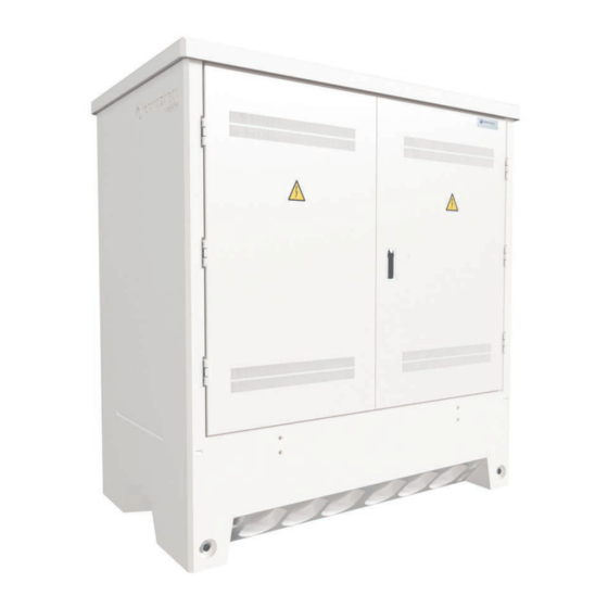
Description and main characteristics cms.21 is a non-walk-in type switching substation with As an option, cms.21 can be supplied tried and tested to internal prefabricated single-block concrete enclosure, for surface arc, with classi cation IAC-AB 16 kA 0.5 s or with classi cation installation. -
Page 5: Medium Voltage Switchgear
90º and 180º. The right hand door can be supplied with di erent types of locks (European barrel, Ormazabal lock, etc.), as well as padlocking with eyebolt of up to Ø 10 mm. The door closes at two points: up and down. First open the right-hand leaf, acting on the lock. - Page 6 The document holder is located on the inside of the right ventilation of cms.21. door, with these General Instructions for cms.21 (IG-247) and the General Instructions of the medium voltage There is an insulating plate on the inside of the door, in the switchgear installed.
-
Page 7: Insulating Operation Platform
General instructions Description and main characteristics cms.21 1.1.3. Insulating operation platform Optionally, cms.21 be tted with an operation platform of insulating material, providing an earth isolated operation surface. Opening out the platform Fold out the platform before carrying out any operation involving the medium voltage system. -
Page 8: Name Plate
Description and main characteristics General instructions cms.21 1.1.4. Name plate cms.21 includes a name plate on the inside of the enclosure. The plate indicates at least the following data: Figure 1.8. Example of the cms.21 name plate 1.1.5. Lighting The cms.21 includes as an option a magnetically fastened light point located at the top of the cells, as long as there is a cubicle or auxiliary services switchboard. -
Page 9: Electrical Specifications
General instructions Description and main characteristics cms.21 1.2. Electrical specifications Characteristic Rated voltage of medium voltage circuits 24 / 36 / 40.5 Number of phases Rated frequency 50 / 60 Characteristics of earthing circuits: 50 (bare copper conductor) (*) Protection earth collector (disconnection) -
Page 10: Mechanical Characteristics
Weight switchgear [kg] Total [kg] 4420 4440 4590 4510 4530 4605 4600 Table 1.2. Weights of cms.21 with schematics of the cgmcosmos system cgm.3 system Voltage 36 kV / 40.5 kV Medium voltage con guration Weight switchgear [kg] Total [kg] 4636... -
Page 11: Dimensions
General instructions Description and main characteristics cms.21 1.3.2. Dimensions Figure 1.9. Dimensions (in mm) of cms.21 A horizontal line in the exterior walls marks zero installation level. IG-247-EN version 02; 08/12/2020... -
Page 12: Transport
Transport General instructions cms.21 Transport 2.1. Elements supplied The cms.21 substation is supplied with the following • General instructions document of the medium voltage components: switchgear. • Levers for the medium voltage switchgear driving Ormazabal General Instructions document IG-247 •... -
Page 13: Sea Transport
In order to prevent damage during transport, we body of cms.21, using a mm 17 wrench (M10 screw). recommend securing the cms.21 to the base of the container, using straps attached rmly to the four “DEHA”... -
Page 14: Storage
Storage Placing two timber battens measuring 2000 x 150 x 20 mm underneath the cms.21 is recommended. It is also Do not store in corrosive or saline environments. recommended that the oor where the equipment is stored should be uniform, stable and level. -
Page 15: Normal Service Conditions
General instructions Normal service conditions cms.21 Normal service conditions The cms.21 has been designed for use outdoors under Altitude: normal working conditions, in accordance with Standard IEC 62271-1. The altitude of the place of installation must not exceed 1000 m. -
Page 16: Installation
In equipment with IAC rating, it is necessary to ensure and assembly operations, taking into account the distances a clearance of 200 mm from the rear wall of the cms.21 to overhead lines, slopes, etc. to any obstacle for proper opening of the rear ap. -
Page 17: Handling
Figure 5.4. Lifting the cms.21 The attached table indicates the recommended power values for the cranes. Remember that these are reference values and that each case must be con rmed by Ormazabal. Rated power of the crane [t] Weight 15.5 DEHA 6000-2.5-0170 anchoring... -
Page 18: Preparing The Location
Installation General instructions cms.21 5.4. Preparing the location Before installing the cms.21 it is necessary to rst excavate The recommended excavation levels are: and have an earthing network, which will later connect to trench levels the cms.21 earth. Length Depth... -
Page 19: Cable Access And Sealing
5.5. Cable access and sealing Fitted in the bottom of the enclosure, below ground, the cms.21 has 18 blanked holes for piped conduits of up to Ø200 mm and 8 blanked holes of Ø50 mm for access of the exterior earthing network or other conduits. The 4 lower blanked holes (mark 6 of Figure 5.7) are set out... -
Page 20: Medium Voltage Cable Connection
General Instructions of the single-core cables must not exceed 240/16 mm and rated medium voltage switchgear, supplied with the cms.21, in voltage 18/30 kV. For other types of cables, please contact Ormazabal. accordance with Standards EN 50180 and EN 50181. -
Page 21: Earthing Circuit Connection
General instructions Installation cms.21 5.6. Earthing circuit connection cms.21 is tted with an internal protective earthing circuit for easy connection of the di erent elements to the external earthing network. 5.6.1. Protective earthing network cms.21 has a protective earthing disconnection box inside. -
Page 22: Exterior Earthing Network
Access of the exterior earthing network to the inside of the cms.21 should be carried out through one of the Ø 50 mm blanked holes, and then through the gap envisaged in the oor. The exterior earthing network should be connected to the protective disconnection box of the cms.21 (mark 6... -
Page 23: Replacing And Introducing The Medium
1. Remove the power from the medium-voltage lines connected to the cms.21. Follow the electricity company's procedure, local rules and electrical safety regulations. 2. Open the cms.21, right hand door by operating the opening handle. Figure 5.14. Right door opening IG-247-EN version 02; 08/12/2020... - Page 24 Installation General instructions cms.21 3. Release the bolts of the left-hand door to open it. Figure 5.15. Release the bolts of the left-hand door. 4. The doors have an interlocking system at 90° and 180°. To release, pull upward on the rod and open the door.
- Page 25 Installation cms.21 6. Disconnect the interior earthing branch which joins the cover to the bottom part of the cms.21 body using a 17 wrench (M10 screw). Figure 5.17. Disconnect the cover's earthing branch. 7. Unscrew the two points which fasten the cover to the body using a 17 wrench (M10 bolt).
- Page 26 Use the 19 wrench (M12 bolt). Figure 5.21. Disconnect the switchgear's earth connectors. 12. Unscrew the attachment points of the switchgear to the rails on the oor of the cms.21. Use the 17 wrench (M10 bolt). Figure 5.22. Unscrew the switchgear fastening points.
-
Page 27: Sequence Of Introduction Of The Switchgear
Sequence of introduction of the switchgear Proceed as follows to introduce the switchgear into the cms.21. 1. Open the cms.21, right hand door by operating the opening handle. Figure 5.23. Right door opening 2. Release the bolts of the left-hand door to open it. - Page 28 Follow the General Instructions of the switchgear. 5. Disconnect the interior earthing branch which joins the cover to the bottom part of the cms.21 body using a 17 wrench (M10 screw). Figure 5.26. Disconnect the cover's earthing branch. IG-247-EN version 02; 08/12/2020...
- Page 29 General instructions Installation cms.21 6. Unscrew the two points which fasten the cover to the body using a 17 wrench (M10 bolt). Figure 5.27. Cover fastening points 7. Remove the four plastic protective caps from the threaded inserts of the cover.
- Page 30 12. Remove the covers to access the switchgear cable compartment. Bolt the attachment points of the switchgear to the rails on the oor of the cms.21. Follow the general instructions of the medium voltage switchgear. 13. Connect the earth connectors of the cables to the switchgear's earthing bar.
-
Page 31: Recommended Sequence Of Operations
General instructions Recommended sequence of operations cms.21 Recommended sequence of operations All accesses and operations recommended in this It is essential to follow the recommended sequence of speci cation must comply with the procedures indicated operations set out in the general instructions of the medium by the electricity company, along with the electricity voltage switchgear. -
Page 32: Maintenance
Regular inspections of the cms.21 are recommended, in line with local regulations. Regular inspections of the medium voltage switchgear are recommended. Shorter regular inspections should... - Page 33 General instructions Notes cms.21 Notes IG-247-EN version 02; 08/12/2020...
- Page 34 Notes General instructions cms.21 Notes IG-247-EN version 02; 08/12/2020...
- Page 36 Ormazabal Subject to change y Cía. without prior notice. For further information, IGORRE contact Ormazabal. Spain www.ormazabal.com...
Need help?
Do you have a question about the cms.21 and is the answer not in the manual?
Questions and answers