Table of Contents

Related Manuals for Fluke DSX-8000


Summarization of Contents
Chapter 1: Get Acquainted
Overview of Features
Describes the Versiv platform's rugged, hand-held instruments for certifying, troubleshooting, and documenting cabling.
Versiv 2 Compatibility
Details incompatibility issues between Versiv 2 and older Versiv testers, and specific module support.
Contact Fluke Networks
Provides contact information for Fluke Networks, including website, phone, and address.
Chapter 2: Get Started
Tutorial: Certify Twisted Pair Cabling
Step-by-step guide to setting up, performing, and saving twisted pair cable certification tests.
Tutorial: Certify Fiber Optic Cabling
Instructions for performing loss/length tests on fiber optic cabling using Smart Remote mode.
Options for Cable IDs
Explains methods for creating and managing cable IDs for test results, including sequential and custom IDs.
Auto Save Function
Details how to enable or disable the auto save function to automatically save test results after each test.
Chapter 3 Certify Twisted Pair Cabling
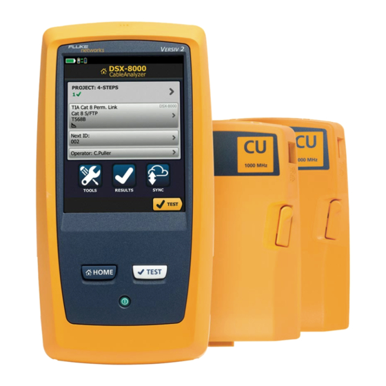
Overview of the DSX CableAnalyzer Modules
Introduces DSX CableAnalyzer modules for certifying, troubleshooting, and documenting twisted pair network cabling.
DSX CableAnalyzer Connectors, Keys, and LEDs
Identifies and explains the connectors, keys, and LEDs on the main DSX tester.
Settings for Twisted Pair Tests
Describes various settings for twisted pair tests, including cable type, NVP, and shield test options.
How to Do an Autotest
Provides instructions and equipment for performing an Autotest on twisted pair cable.
Twisted Pair Autotest Results
Explains the results screens for twisted pair autotests, including WIRE MAP, PERFORMANCE, and DIAGNOSTIC tabs.
Automatic Diagnostics
Details how the tester automatically provides fault information when a twisted pair Autotest fails.
PASS*/FAIL* Results
Explains the meaning of PASS* and FAIL* results, indicating marginal measurements within the tester's accuracy range.
WIRE MAP Tab
Describes the WIRE MAP tab, which shows cable connections and their status relative to the outlet configuration.
Chapter 4: Test Twisted Pair Through a PoE Device (DSX-5000)
How to Turn On the AC Wire Map Test
Guide to enabling the AC wire map test for links connected through midspan PoE devices.
When to Keep the AC Wire Map Test Off
Information on when to disable the AC wire map test to optimize Autotest time and avoid interference.
How to Do an Autotest Through a PoE Device
Step-by-step instructions for performing an Autotest on cabling connected through a PoE device.
Chapter 5: Certify Coaxial Cabling
Set the Reference for Coaxial Tests
Procedure for setting the reference for coaxial tests to establish a baseline for measurements.
Settings for Coaxial Tests
Details the settings for coaxial tests, including module, cable type, NVP, and store plot data options.
How to Do an Autotest
Instructions for performing an autotest on coaxial cabling, including connection and setup steps.
Tests Without a Remote
Describes how to perform length, resistance, and HDTDR tests without a remote tester.
Chapter 6: Diagnose Copper Test Failures
Fault Information
Explains how the tester provides fault information, including wire maps and analyzer plots, for failed twisted pair autotests.
Causes of Twisted Pair Test Failures
Lists common causes for test failures in twisted pair cabling, categorized by fault type.
The HDTDR Analyzer
Explains the HDTDR analyzer's function in showing return loss relative to distance and identifying causes of return loss failures.
The HDTDX Analyzer
Details the HDTDX analyzer's role in showing crosstalk signals relative to distance and identifying causes of NEXT and ACR-F failures.
Chapter 7: Clean Fiber Endfaces
Always Clean Endfaces Before Tests
Emphasizes the importance of cleaning fiber connectors and inspects endfaces before making connections.
How to Use Wipes, Swabs, and Solvent
Provides instructions for using cleaning supplies like wipes, swabs, and solvent to clean fiber connectors.
To Clean Bulkhead Connectors
Step-by-step guide for cleaning bulkhead connectors, including using a video probe and dry swabs.
To Clean Optical Connectors on the Modules
Instructions for cleaning optical connectors on modules, including ferrules and photodiode lenses.
Chapter 8: Inspect Fiber Endfaces
Connectors, Keys, and LEDs
Identifies and explains the connectors, keys, and LEDs on the Versiv 2 tester.
The Home Screen for FiberInspector Tests
Explains the HOME screen for FiberInspector tests, showing important test settings before test execution.
How to Do the FiberInspector Test
Step-by-step guide on performing a FiberInspector test, including using the probe and saving images.
Automatic Analysis of Scratches and Defects
Details how the tester automatically analyzes scratches and defects on fiber endfaces, assigning PASS/FAIL results based on criteria.
Chapter 9: Certify Fiber Cabling
Overview of the CertiFiber Pro Optical Loss Test Set Modules
Introduces CertiFiber Pro OLTS modules for certifying, troubleshooting, and documenting optical fiber installations.
CertiFiber Pro Connectors, Keys, and LEDs
Identifies and explains the connectors, keys, and LEDs on the main CertiFiber Pro tester.
Requirements for Reliable Fiber Test Results
Outlines procedures and conditions necessary for obtaining reliable fiber test results and ensuring tester accuracy.
About the Reference for Fiber Tests
Explains the importance of setting the reference for loss measurements and when to perform this procedure.
Autotest in Smart Remote Mode
Details how to perform autotests on dual-fiber cabling in Smart Remote mode, including bi-directional measurements.
Autotest in Loopback Mode
Explains how to perform tests on spools and segments of uninstalled cable using Loopback mode.
Autotest in Far End Source Mode
Guide to measuring loss at two wavelengths on a single fiber using the Far End Source mode.
Bi-directional Tests
Explains when and how to perform bi-directional tests in Smart Remote and Loopback modes for more accurate results.
Chapter 10: The Power Meter and Light Source
How to Monitor Power and Loss
Guide to monitoring optical power and loss using the power meter, including measuring levels and comparing to reference.
How to Control the Light Source
Instructions on controlling the light source manually or automatically for tests in Far End Source mode.
Chapter 11: The OptiFiber Pro OTDR Module
Overview of the OTDR Module
Introduces OptiFiber Pro OTDR modules for locating, identifying, and measuring events in singlemode and multimode fibers.
OptiFiber Pro Connectors, Keys, and LEDs
Identifies and explains the connectors, keys, and LEDs on the main Versiv tester with OptiFiber Pro OTDR module.
Settings for OTDR Tests
Describes settings for OTDR tests, including Manual OTDR and SmartLoop OTDR modes.
How to Use the Measurement Cursor on the OTDR Trace
Guide on using the measurement cursor on OTDR traces to measure distance and loss along cabling.
How to Quickly Try Different OTDR Settings
Instructions on quickly changing OTDR settings for trials on the same fiber after an OTDR test.
How To Do Bi-directional Tests on Single Fibers
Steps for performing bi-directional OTDR tests on single fibers, including setting up launch compensation and connections.
How To Do Bi-directional Tests for All IDs in a Set
Procedure to test all links from End 1, then retest from End 2 for all IDs in a set.
Real Time Trace
Explains the real time trace feature for observing OTDR trace changes and performing tasks like finding intermittent problems.
The FaultMap Test
Details the FaultMap test for recording connections and identifying bad connections with high reflectance.
The SmartLoop Test
Details the SmartLoop test, allowing connection of fiber ends for OTDR results on both fibers with reduced test time.
Chapter 12: The OptiFiber Pro HDR OTDR Module
Overview of the HDR OTDR Module
Introduces the OptiFiber Pro HDR OTDR module for locating and identifying events in singlemode fibers, including PON installations.
OptiFiber Pro HDR Connectors, Keys, and LEDs
Identifies and explains the connectors, keys, and LEDs on the main Versiv unit with the OptiFiber Pro HDR OTDR module.
Settings for HDR OTDR Tests
Describes settings for Auto and Manual HDR OTDR tests, including module, test type, and manual settings.
How to Use the Measurement Cursor on the OTDR Trace
Guide on using the measurement cursor on OTDR traces to measure distance and loss along cabling.
How to Quickly Change OTDR Settings After a Test
Guide to quickly changing OTDR settings for trials on the same fiber after an HDR OTDR test.
The FaultMap Test
Details the FaultMap test for recording connections and identifying bad connections with high reflectance.
The SmartLoop Test
Details the SmartLoop test, allowing connection of fiber ends for OTDR results on both fibers with reduced test time.
Chapter 13: OTDR Span and Event Editing Functions
Overview of Features
Introduces span and event editing functions available in OptiFiber Pro and OptiFiber Pro HDR modules.
How to Edit a Loss Event
Instructions on changing a loss event's type to APC Connector and recalculating results.
How to Use the Span Function
Explains how to use the Span function to limit OTDR results to a specific section of fiber.
Chapter 14: The Visual Fault Locator
Visual Fault Locator Applications
Describes applications of the visual fault locator for verifying fiber continuity, identifying connectors, and finding faults.
How to Use the VFL
Instructions on using the visual fault locator, including connecting the probe, changing modes, and identifying red light.
Chapter 15: Diagnose Problems in Fiber Links
Common Causes of Problems in Fiber Links
Presents survey results on common causes of fiber link problems like dirty connectors, poor polishing, and bad splices.
Causes of Loss/Length Test Failures
Lists causes for loss/length test failures, including dirty connectors, kinks, bad splices, and incorrect settings.
Causes of OTDR Test Failures
Details common causes for OTDR test failures, such as dirty connectors, mismatched fibers, and incorrect launch cords.
Chapter 16: Manage Test Results
View Saved Results
Instructions on how to view test results within projects, on a USB flash drive, or in the cloud via LinkWare Live.
How to Add a Result to a Saved Result
Steps to save results from different tests into a single cable ID, ensuring settings agreement.
How to Replace a Saved Result that Failed
Guide on replacing a saved result with the same or different test settings, including overwriting options.
Delete, Rename, and Move Results
Explains how to manage saved results by deleting, renaming, or moving them between projects.
Manage Results on a Flash Drive
Instructions for exporting, importing, and deleting projects and results to/from a USB flash drive.
Upload Results to a PC
Details the process of uploading test results to a PC using LinkWare PC software or the LinkWare Live web application.
Memory Capacity
Provides approximate numbers of tests that can be saved in the main tester, depending on test type and memory usage.
Chapter 17: Use Projects
Why Use Projects?
Explains the benefits of using the ProjX™ management system for organizing jobs, specifying tests, and monitoring progress.
Tutorial: Make a New Project
Step-by-step guide to creating a new project, including naming, specifying operator, and setting up tests.
Tutorial: How to Use a Project for Tests with CableAnalyzer Module
Guide on using a project for tests with a CableAnalyzer module, assuming prior project creation.
Tutorial: How to Use a Project for Tests with OptiFiber Pro and CertiFiber Pro Modules
Tutorial on using projects for OTDR tests with OptiFiber Pro and loss/length tests with CertiFiber Pro modules.
Make ID Sets for Twisted Pair and Fiber Cabling
Instructions on creating ID sets for naming test results, including sequential and custom IDs for copper and fiber.
How to Manage Projects
Explains how to rename, copy, delete projects, and manage them on a flash drive.
About LinkWare Live
Information on using the LinkWare Live web application for managing projects from desktop or mobile devices.
Chapter 18: Sync Projects with LinkWare™ Live
Sign Up for a LinkWare Live Account
Steps to create a LinkWare Live account, including email verification and activation.
How to See the Tester’s MAC Address
Instructions on finding the wired and Wi-Fi MAC addresses of the tester, which may be required for network registration.
Use LinkWare Live Through a Wired Ethernet Network
Guide to connecting the tester to a wired network for LinkWare Live access and syncing projects.
Use LinkWare Live Through a Wi-Fi Network
Instructions for connecting the tester to a Wi-Fi network, including adapter recommendations and settings.
When You Cannot Sync a Deleted Project
Addresses issues with syncing deleted projects and explains how LinkWare Live uses unique IDs.
Change the Network Settings
Details how to access and change wired or Wi-Fi network settings on the tester, such as static addressing.
Chapter 19: Custom Media and Test Limits
Make a Custom Copper Cable Type
Guide to creating custom cable types for twisted pair or coaxial installations not listed in the tester's database.
Change the NVP
Explains how to adjust the NVP value to improve the accuracy of length measurements in copper cabling.
Set the NVP to a Specified Value
Procedure to set the NVP to a manufacturer-specified value for more accurate length calculations.
Find a Cable's Actual NVP
Instructions on using the NVP screen to adjust measured length to match a known cable length.
Make a Custom Outlet Configuration
Guide to creating custom outlet configurations for T568A or T568B standards, including enabling/disabling pairs and naming.
Make a Custom Fiber Type
Instructions on creating custom fiber types by specifying name, category, IOR, and backscatter values.
Make a Custom Fiber Test Limit
Guide to creating custom test limits for fiber tests, allowing entry of minimum/maximum values for pass/fail criteria.
Chapter 20: Maintenance
Verify Operation
Describes the tester's self-test process upon turning it on and troubleshooting steps for errors or failure to turn on.
Clean the Tester
Instructions for cleaning the touchscreen and case using a soft, lint-free cloth with water or mild detergent.
Clean the FI-1000 Video Probe
Guide to cleaning the FI-1000 video probe's case and lens using a soft cloth and cleaning solution.
See Information About the Tester
Explains how to view information about the tester, attached modules, adapters, and remote testers.
Update the Software
Details how to update the tester's software using a PC, an updated main tester, or LinkWare Live.
Use a PC to Update the Software
Step-by-step instructions for updating the tester's software using a PC and LinkWare PC software.
Use an Updated Main Tester to Update Other Testers
Guide on using an updated main tester to update software on remote testers or other main testers.
Extend the Life of the Battery
Provides tips for extending battery life, including avoiding full discharge and temperature extremes.
Traceable Calibration Period
Recommends calibration at an Authorized Fluke Networks Service Center every 12 months for accuracy.
If the Tester Does Not Operate as Usual
Troubleshooting guide for unusual tester behavior, error messages, or failure to turn on.
Chapter 21: Specifications
Environmental and Regulatory Specifications
Details operating and storage temperatures, humidity, vibration, and shock specifications.
Power
Provides specifications for battery type, charging temperature, battery life, charge time, and power adapter.
DSX-8000 Module: Tests and Frequencies Supported
Lists the twisted pair and coaxial cabling tests and frequency ranges supported by the DSX-8000 module.
DSX-8000 Measurement Accuracy
Outlines the worst-case accuracy performance parameters for DSX-8000 modules per IEC Guidelines.
DSX-5000 CableAnalyzer Module Specifications
Provides specifications for DSX-5000 modules, including autotest times and supported cable types.
DSX-5000 Measurement Accuracy
Details the Level V accuracy performance parameters for DSX-5000 modules per IEC Guidelines.
OptiFiber Pro OLTS Module Specifications
Provides specifications for CertiFiber Pro OLTS modules, including wavelengths and power measurement ranges.
OptiFiber Pro OTDR Module Specifications
Lists specifications for OptiFiber Pro OTDR modules, covering OTDR ports, wavelengths, and dead zones.
OptiFiber Pro HDR OTDR Module Specifications
Details specifications for OptiFiber Pro HDR OTDR modules, including maximum distance and accuracy parameters.
Visual Fault Locator
Provides specifications for the Visual Fault Locator, including on/off control, output power, and laser safety.
Appendix A: Tests on Long Fiber Links with the OptiFiber Pro OTDR
Make a Custom Fiber Type, If Necessary
Instructions for creating a custom fiber type when the required type is not in the tester's list, using manufacturer values.
Use a Launch Cord of the Correct Type
Guidance on selecting launch cords with properties similar to the link to ensure accurate loss measurements.
Appendix C: Reference Methods for Fiber Cabling
1 Jumper Reference
Describes the 1 jumper reference method, including connections and suitability for premises fiber testing.
2 Jumper Reference
Explains the 2 jumper reference method, suitable for links where one end connects directly to active equipment.
3 Jumper Reference
Details the 3 jumper reference method, which includes only the fiber in the link for loss results.
Modified 1 Jumper Reference
Shows modified connections for 1 jumper results when correct adapters are unavailable, allowing cords to stay connected.
Need help?
Do you have a question about the DSX-8000 and is the answer not in the manual?
Questions and answers