Fluke DTX Series User Manual
Cable analyzer
Hide thumbs
Also See for DTX Series:
- User manual (82 pages) ,
- Technical reference handbook (250 pages)

Related Manuals for Fluke DTX Series


Summary of Contents for Fluke DTX Series
- Page 1 DTX Series CableAnalyzer Users Manual PN 2142201 April 2004 © 2004 Fluke Corporation. All rights reserved. Printed in USA. All product names are trademarks of their respective companies.
- Page 2 LIMITED WARRANTY AND LIMITATION OF LIABILITY Each Fluke Networks product is warranted to be free from defects in material and workmanship under normal use and service. The warranty period is one year and begins on the date of purchase. Parts, accessories, product repairs and services are warranted for 90 days. This war-...
-
Page 3: Table Of Contents
Table of Contents Title Page Overview of Features ....................1 Registration ........................2 Contacting Fluke Networks ..................2 Accessing the Technical Reference Handbook............3 Additional Resources for Cable Testing Information ..........3 Unpacking........................4 DTX-1800........................4 DTX-1200........................4 DTX-LT........................5 Safety Information ....................... - Page 4 DTX Series CableAnalyzer Users Manual Certifying Twisted Pair Cabling..................24 Preparing to Save Tests.................... 25 Autotest on Twisted Pair Cabling................26 Autotest Summary Results..................29 Automatic Diagnostics ..................... 30 PASS*/FAIL* Results....................31 Cable ID Options ...................... 32 Memory Functions ......................33 Formatting the Memory Card (DTX-1800 and DTX-1200)........
- Page 5 List of Figures Figure Title Page Tester Front Panel Features ....................8 Tester Side and Top Panel Features..................10 Smart Remote Features ....................... 12 Removing the Battery Pack....................15 Smart Remote Battery Status Shown After Power-Up ............15 Attaching and Removing Adapters ..................16 Handling Guidelines for Permanent Link Adapters............
- Page 6 DTX Series CableAnalyzer Users Manual...
-
Page 7: Overview Of Features
• Automatic diagnostics report distance to and likely Overview of Features causes of common faults. The DTX Series CableAnalyzers are rugged, hand-held • Toner feature helps you locate jacks and instruments used to certify, troubleshoot, and document automatically starts an Autotest upon tone twisted pair and fiber cabling installations. -
Page 8: Registration
Note • Smart remote with optional fiber module can be used If you contact Fluke Networks about your tester, with Fluke Networks OF-500 OptiFiber Certifying have the tester's software and hardware version OTDR for loss/length certification. -
Page 9: Accessing The Technical Reference Handbook
Additional Resources for Cable • Testing Information Korea: 82 2 539-6311 • Singapore: +65-6738-5655 The Fluke Networks Knowledge Base answers common questions about Fluke Networks products and provides • Taiwan: (886) 2-227-83199 articles on cable testing techniques and technology. •... -
Page 10: Unpacking
Users Manual DTX-1200 Unpacking • DTX-1200 CableAnalyzer with lithium-ion battery The DTX Series CableAnalyzers come with the accessories pack listed below. If something is damaged or missing, contact • DTX-1200 SmartRemote with lithium-ion battery pack the place of purchase immediately. -
Page 11: Dtx-Lt
USB cable for PC communications Do not modify the tester. • Two ac adapters • Use only ac adapters approved by Fluke • DTX Series CableAnalyzer Users Manual Networks for use with the DTX tester to charge • the battery or power the tester. - Page 12 DTX Series CableAnalyzer Users Manual • Caution Never connect the tester to any telephony inputs, systems, or equipment, including ISDN. To avoid disrupting network operation, to avoid Doing so is a misapplication of this product, damaging the tester or cables under test, to...
- Page 13 See pages 16 and 17 for To avoid possible eye damage caused by important handling information. hazardous radiation, when using the fiber modules follow the safety guidelines given in the DTX-MFM/SFM Fiber Module Users Manual or the DTX Series CableAnalyzer Technical Reference Handbook.
-
Page 14: Getting Acquainted
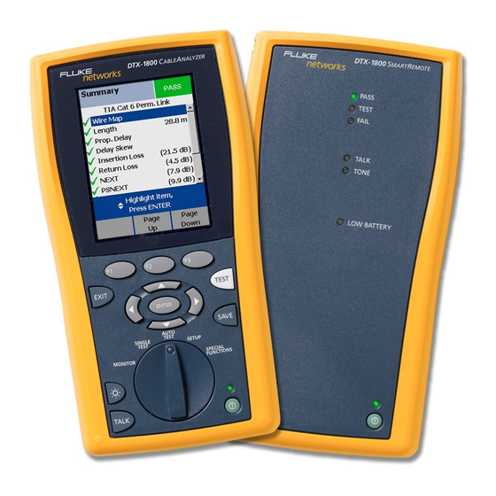
DTX Series CableAnalyzer Users Manual Physical Features Getting Acquainted Figures 1 and 2 describe the tester’s features. Figure 3 The following sections introduce the tester's basic describes the smart remote’s features. features. EXIT TEST ENTER SAVE AUTO TEST SINGLE SETUP... - Page 15 Getting Acquainted LCD display with backlight and adjustable brightness. : Press to turn the display backlight on or off. Hold for 1 second to adjust the display contrast. : Starts the currently selected test. Activates the H B C A D tone generator for twisted pair cabling if no smart : Arrow keys for navigating remote is detected.
- Page 16 DTX Series CableAnalyzer Users Manual amd33f.eps Figure 2. Tester Side and Top Panel Features...
- Page 17 “Powering the Tester” on page 14. DTX-1200) ports for uploading test reports to a PC and updating the tester’s software. The RS-232C port uses a custom DTX cable available from Fluke Networks. Figure 2. Tester Side and Top Panel Features (cont.)
- Page 18 DTX Series CableAnalyzer Users Manual PASS TEST FAIL TALK TONE LOW BATTERY TEST TALK amd30f.eps Figure 3. Smart Remote Features...
- Page 19 Getting Acquainted : Starts the test currently selected on the main unit. Note Activates the tone generator for twisted pair cabling if The LEDs also act as a battery gauge. See Figure no main tester is detected. The test starts when both 5 on page 15.
-
Page 20: Powering The Tester
DTX Series CableAnalyzer Users Manual • Powering the Tester If the battery does not reach full charge within 6 hours, the battery LED flashes red. Verify that the • You may charge the battery when it is attached or battery was within the temperature range given detached from the tester. - Page 21 Getting Acquainted PASS TEST 91 % - 100 % FAIL PASS TALK TONE 75 % - 90 % TEST 59 % - 74 % LOW BATTERY FAIL 42 % - 58 % TALK TEST 25 % - 41 % TALK TONE 9 % - 24 % LOW BA...
-
Page 22: About Link Interface Adapters
DTX Series CableAnalyzer Users Manual About Link Interface Adapters Link interface adapters provide the correct jacks and interface circuitry for testing different types of twisted pair LAN cabling. The channel and permanent link interface adapters provided are suitable for testing cabling up to Cat 6. - Page 23 Getting Acquainted 7 in (18 cm) minimum 7 in (18 cm) minimum radius or bend DSP-7XXX CABLE ANALYZER EXIT EXIT TEST TEST ENTER ENTER SAVE SAVE AUTO AUTO SINGLE SINGLE TEST TEST TEST TEST SETUP SETUP MONITOR MONITOR SPECIAL SPECIAL FUNCTIONS FUNCTIONS 7 in (18 cm)
- Page 24 DTX Series CableAnalyzer Users Manual The DTX-PLA001 universal permanent link adapter has a removable personality module. These may be changed to customize the adapter for different jack configurations. To change the personality module, do the following Static sensitive (refer to Figure 8):...
-
Page 25: Twisted Pair Test Settings
Twisted Pair Test Settings To access the settings, turn the rotary switch to SETUP, Twisted Pair Test Settings to highlight Twisted Pair; then press Table 1 describes the settings that apply to twisted pair cabling tests. Table 1. Twisted Pair Test Settings Setting Description SETUP >... - Page 26 DTX Series CableAnalyzer Users Manual Table 1. Twisted Pair Test Settings (cont.) Setting Description SETUP > The Outlet Configuration setting determines which cable pairs are tested and which pair numbers are Twisted Pair > assigned to the pairs. Outlet Configuration...
- Page 27 Twisted Pair Test Settings Table 1. Twisted Pair Test Settings (cont.) Setting Description SETUP > Instrument Yes: the tester displays and saves plot data for frequency-based tests such as NEXT, return loss, Settings > Store Plot and attenuation. This lets you include plots on test reports created in LinkWare software. Data No: plot data is not displayed or saved, which lets you save more results.
-
Page 28: Setting The Reference
DTX Series CableAnalyzer Users Manual You do not need to set the reference after changing link Setting the Reference interface adapters. The reference procedure sets a baseline for insertion loss, Note ELFEXT, and dc resistance measurements. Turn on the tester and smart remote and let Run the tester’s reference procedure at the following... - Page 29 Setting the Reference To set the reference, do the following: Attach permanent link and channel adapters and make the connections shown in Figure 9. Turn the rotary switch to SPECIAL FUNCTIONS and turn on the smart remote. Permanent link adapter Highlight Set Reference;...
-
Page 30: Certifying Twisted Pair Cabling
DTX Series CableAnalyzer Users Manual Certifying Twisted Pair Cabling Figure 10 shows the equipment needed for certifying twisted pair cabling. PASS TEST FAIL TALK TONE LOW BATTERY EXIT TEST ENTER SAVE AUTO TEST SINGLE SETUP TEST SPECIAL MONITOR FUNCTIONS TEST... -
Page 31: Preparing To Save Tests
Certifying Twisted Pair Cabling Preparing to Save Tests • Check the memory space available: Current Folder: Select an existing folder or press Create Folder to create a new folder. Insert a memory card (DTX-1800 and 1200), turn the rotary switch to SPECIAL FUNCTIONS; then select Set the plot data storage option: Memory Status. -
Page 32: Autotest On Twisted Pair Cabling
DTX Series CableAnalyzer Users Manual Autotest on Twisted Pair Cabling Attach adapters appropriate for the job to the tester Press on the tester or smart remote. To stop the test and the smart remote. at any time, press Turn the rotary switch to SETUP, then select Twisted... - Page 33 Certifying Twisted Pair Cabling Horizontal cabling Optional consolidation point Work area Patch panel Wall outlet Start permanent permanent link link PASS TEST FAIL TALK TONE Tester with permanent Smart remote with LOW BATTERY link adapter permanent link adapter EXIT TEST ENTER SAVE AUTO...
- Page 34 DTX Series CableAnalyzer Users Manual Horizontal cabling Hub or switch Optional consolidation point Patch cord from hub or Work area switch Patch Wall panels outlet Start Patch channel cord channel from PC PASS TEST FAIL TALK TONE LOW BATTERY Tester with...
-
Page 35: Autotest Summary Results
Certifying Twisted Pair Cabling Autotest Summary Results Figure 13 describes the Autotest Summary screen. PASS: All parameters are within limits. FAIL: One or more parameters exceeds the limit. PASS*/FAIL*: One or more parameters are within the tester’s accuracy uncertainty range, and the “*” notation is required by the selected test standard. -
Page 36: Automatic Diagnostics
DTX Series CableAnalyzer Users Manual Automatic Diagnostics can take to solve the problem. A failed test may produce more than one diagnostic screen. In this case, press If an Autotest fails, press Fault Info for diagnostic to see additional screens. -
Page 37: Pass*/Fail* Results
Certifying Twisted Pair Cabling PASS*/FAIL* Results For a PASS* result you should look for ways to improve the cabling installation to eliminate the marginal A result marked with an asterisk means that performance. measurements are in the tester’s accuracy uncertainty range (Figure 15) and the “*”... -
Page 38: Cable Id Options
DTX Series CableAnalyzer Users Manual Cable ID Options To create a list of sequential IDs, do the following: You can select cable IDs from a pre-generated list or you On the Auto Sequence screen, select a template. can create an ID after each test. -
Page 39: Memory Functions
Memory Functions Setting the Storage Location (DTX-1800 and Memory Functions DTX-1200) All DTX testers have internal memory that can store at To set the destination for saved results turn the rotary least 250 Autotest results, including graphical data. The switch to SETUP, select Instrument Settings, select Result maximum capacity of internal memory depends on the Storage Location;... -
Page 40: Moving And Deleting Results
DTX Series CableAnalyzer Users Manual Moving and Deleting Results All Models To delete results or folders, do the following: DTX-1800, DTX-1200 To move or copy all results from internal memory to the Turn the rotary switch to SPECIAL FUNCTIONS, then memory card, turn the rotary switch to SPECIAL select View/Delete Results. -
Page 41: Uploading Results To A Pc
Turn on the tester. Select the records you want to import; then click OK. Connect the tester to the PC with the USB cable included or the DTX serial cable available from Fluke Networks. Insert the memory card containing results into the PC’s memory card reader. -
Page 42: Options And Accessories
DTX-PLA001 Universal Permanent Link Adapters, set of 2 DTX-PLA001S Cat 6 Centered Personality Module DSP-PM06 Personality modules for IDC and legacy cabling systems DSP-PMxx Many models are available. Contact Fluke Networks or visit the Fluke Networks website for details. -continued-... - Page 43 Options and Accessories Table 2. Options and Accessories (cont.) Fluke Networks Option or Accessory Model Number Siemon Tera Channel Adapter DTX-CHA011 Siemon Tera Permanent Link Adapter DTX-PLA011 Siemon Tera Adapter Kit DTX-TERA Nexans GG45 Channel Adapter DTX-CHA012 Nexans GG45 Permanent Link Adapter...
- Page 44 MultiMedia Card (MMC) Reader, USB DSP-MCR-U MultiMedia Card (MMC) Carry Case MMC CASE IntelliTone IT100 Probe MT-8200-53A LinkWare Cable Test Management Software LinkWare (You may download this at no charge from the Fluke Networks website.) LinkWare Stats Statistical Report Option LinkWare-Stats -continued-...
- Page 45 Options and Accessories Table 2. Options and Accessories (cont.) Fluke Networks Option or Accessory Model Number DTX-1800 Main Unit Replacement with Battery Pack DTX-1800/MU DTX-1800 Smart Remote Replacement with Battery Pack DTX-1800/RU DTX-1200 Main Replacement with Battery Pack DTX-1200/MU DTX-1200 Smart Remote Replacement with Battery Pack...
-
Page 46: About Linkware And Linkware Stats Software
Help on the LinkWare menu. The LinkWare Cable Test Management software Updates to LinkWare software are available on the Fluke included with your tester lets you do the following: Networks website. • Upload test records to PC. -
Page 47: Maintenance
Use only specified replacement parts for user- year to ensure that it meets or exceeds the published replaceable items. accuracy specifications. Contact an authorized Fluke Networks Service Center for information on getting your • Use only Fluke Networks authorized service tester calibrated. -
Page 48: Updating The Tester's Software
Save the file to To get a software update, download the update from your hard drive. the Fluke Networks website or contact Fluke Networks to Make the connections shown in Figure 16 using the get the update by other means. - Page 49 Maintenance Select Utilities > DTX Utilities > Software Update from the LinkWare menu, locate and select the .dtx (DTX update) file; then click Open. When the tester is updated, it reboots, then prompts you about updating the smart remote’s software. Press OK to update the smart remote’s software.
-
Page 50: Updating With Another Tester
DTX Series CableAnalyzer Users Manual Updating with Another Tester You can update a tester’s software using another tester that is already updated. Use link interface adapters to connect an updated tester or smart remote to a tester or smart remote that needs updating (Figure 17). -
Page 51: Updating With A Memory Card (Dtx-1800, Dtx-1200)
Press Yes to start the update procedure. Download the DTX CableAnalyzer update file from the Fluke Networks website, or contact Fluke When the tester is updated, it reboots, then prompts Networks to get the update by other means. You you about updating the smart remote’s software. -
Page 52: Certification And Compliance
DTX Series CableAnalyzer Users Manual Safety Certification and Compliance CAN/CSA-C22.2 No. 1010.1-92 + Amendment 2: 1997; Overvoltage Category II, Pollution degree 2, 30 V. Conforms to relevant Australian standards N10140 EN61010, 2nd Edition, MEASUREMENT (Installation) CATEGORY I, Pollution Degree 2 per IEC1010-1 refers to... -
Page 53: Index
Index running, 26 connections Summary screen, 29 channel, 28 —*— permanent link, 27 connectors * in results, 31 —B— main tester, 11 RJ11 (telephone), 6 backbone template, 32 —A— smart remote, 13 backlight, 9 accessories battery, 14 buttons, 9 optional, 36 —D—... - Page 54 DTX Series CableAnalyzer Users Manual Fluke Networks —L— permanent link contacting, 2 interface adapters, 16 language, 14 Knowledge Base, 3 test connections, 27 Length Units, 14 folders power, 14 link interface adapters, 16 deleting, 34 Power Line Frequency, 14 LinkWare (uploading results), 35...
- Page 55 (continued) Index with a PC, 42 —W— with another tester, 44 warnings, 5, 41 version, 42 Store Plot Data, 21 Summary screen, 29 —T— talk feature, 13 talk mode, 9 template, 32 Test Limit, 19 Time, 14 tone generator, 26 smart remote, 13 tester, 9 —U—...
- Page 56 DTX Series CableAnalyzer Users Manual...
Need help?
Do you have a question about the DTX Series and is the answer not in the manual?
Questions and answers