Sign In
Upload
Manuals
Brands
Fluke Manuals
Test Equipment
DSX-8000
Fluke DSX-8000 Manuals
Manuals and User Guides for Fluke DSX-8000. We have
1
Fluke DSX-8000 manual available for free PDF download: Technical Reference Handbook
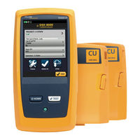
Fluke DSX-8000 Technical Reference Handbook (700 pages)
Brand:
Fluke
| Category:
Test Equipment
| Size: 31.22 MB
Table of Contents
Table of Contents
3
Chapter 1 Get Acquainted
37
Overview of Features
37
Versiv 2 Compatibility
38
Contact Fluke Networks
38
Register Your Product
39
Additional Resources
39
Supplements and Updated Manuals
39
Symbols
40
Wsafety Information
42
For the Main Tester
42
For DSX Modules and Twisted Pair Adapters
44
For Certifiber Pro OLTS Modules
46
For Optifiber Pro OTDR Modules
47
Main Unit Connectors, Keys, and Leds
49
Main Tester as a Remote
49
AC Adapter and Battery
53
Charge the Battery
54
Check the Battery Status
55
Mode
56
Verify Operation
58
How to Use the Touchscreen
58
The HOME Screen
61
How to Enter Text
64
Set User Preferences
66
Language
66
Date and Time Settings and Formats
66
Number Format
67
Units for Length Measurements
67
Power-Down and Backlight Timeout Periods
67
Audible Tone
68
Power Line Frequency
68
Display Brightness
69
Import User Preferences from a File
69
How to Install a Strap
69
How to Remove or Install a Module
70
About Linkware Applications
72
Linkware PC Cable Test Management Software
72
The Linkware Live Web Application
72
Linkware Stats
72
Chapter 2 Get Started
73
Tutorial: Certify Twisted Pair Cabling
73
Step 1: See How Much Memory Is Available
74
Step 2: Set up a Twisted Pair Test
74
Step 3: Turn off the Auto Save Function
76
Step 4: Do an Autotest
76
Step 5: Look at the Results
76
Step 6: Save the Results
77
Tutorial: Certify Fiber Optic Cabling
79
Step 1: See How Much Memory Is Available
79
Step 2: Set up a Loss/Length Test
81
Step 3: Turn off the Auto Save Function
82
Step 4: Set the Reference
83
Step 5: Measure the Loss of the Test Reference Cords You will Add
85
Step 7: Look at the Results
87
Step 8: Save the Results
87
Tutorial: Do a Bi-Directional Smartloop Test
88
Step 1: See How Much Memory Is Available
89
Step 2: Set up a Bi-Directional Smartloop Test
89
Step 3: Turn off the Auto Save Function
91
Step 4: Enter Ids for the Fibers
91
Step 5: Set up Launch Fiber Compensation
91
Step 6: Do the Smartloop Test
94
Step 7: Look at the Results
96
Step 8: Save the Results
97
Buttons to Do Tests and Save Results
97
Options for Cable Ids
100
Automatic Increment Function for Cable Ids
101
Auto Save Function
101
Tutorial: Make a Set of Sequential Cable Ids
102
About Projects
104
About Linkware Live
104
Chapter 3 Certify Twisted Pair Cabling
105
Overview of the DSX Cableanalyzer Modules
105
DSX Cableanalyzer Connectors, Keys, and Leds
106
About Link Interface Adapters
110
How to Prevent Damage to the Adapter Cables
110
Adapters for DSX-8000 and DSX-5000 Modules
112
The DSX Cableanalyzer Home Screen
114
Make Sure Your Tester Is Ready to Certify Twisted Pair Cabling
117
Set the Reference
118
Settings for Twisted Pair Tests
120
How to Do an Autotest
126
Bad Patch Cord" Message
131
How to Certify Patch Cords
131
Twisted Pair Autotest Results
132
Automatic Diagnostics
133
PASS*/FAIL* Results
134
WIRE MAP Tab
135
PERFORMANCE Tab
140
Scalar Results
142
Length, Propagation Delay, and Delay Skew
142
Loop Resistance
145
Continuous Tests
147
Frequency-Domain Results
147
How to Save Frequency-Domain Results as a Plot or a Table
147
Insertion Loss
152
Return Loss
154
Impedance
156
NEXT (Near-End Crosstalk)
158
PS NEXT (Power Sum Near End Crosstalk)
160
ACR-N (Attenuation to Crosstalk Ratio at the Near End)
161
PS ACR-N (Power Sum Attenuation to Crosstalk Ratio, Near End)
163
ACR-F (Attenuation to Crosstalk Ratio, Far End)
165
Ps Acr-F
168
Balance Measurements
169
Differential and Common-Mode Signals
169
Effects of Unbalanced Impedance in a Wire Pair
169
Balance Measurements Available
171
Resistance Unbalance
172
Resistance Unbalance Within Pairs (PAIR UBL)
172
Resistance Unbalance between Pairs (P2P UBL)
176
CMRL (Common-Mode Return Loss)
178
CDNEXT (Common-Mode to Differential-Mode Near-End Crosstalk)
180
TCL (Transverse Conversion Loss)
183
ELTCTL (Equal Level Transverse Conversion Transfer Loss)
185
DIAGNOSTIC and FAULT INFO Tabs
186
About Db Rules
186
Db Rule
188
67 Db Rule for ACR-F and PS ACR-F
189
How to Use the Tone Generator
191
How to Use the Talk Function
193
Long-Range Communication Mode (DSX-5000)
194
About the Axtalk Analyzer Kit
194
Chapter 4 Test Twisted Pair through a Poe Device (DSX-5000)
195
How to Turn on the AC Wire Map Test
195
When to Keep the AC Wire Map Test off
196
How to Do an Autotest through a Poe Device
196
AC Wire Map Results
198
Chapter 5 Certify Coaxial Cabling
201
Set the Reference for Coaxial Tests
201
Settings for Coaxial Tests
203
How to Do an Autotest
205
Coaxial Autotest Results
208
Length and Propagation Delay
210
Resistance
211
Impedance
212
Insertion Loss
214
About Splitters
215
Tests Without a Remote
216
Continuous Tests
219
Chapter 6 Diagnose Copper Test Failures
221
Fault Information
221
Types and Order of Faults Reported
222
When the FAULT INFO Tab Does Not Show
223
Causes of Twisted Pair Test Failures
223
Causes of Coaxial Test Failures
228
The HDTDR Analyzer
230
The HDTDX Analyzer
236
How to Use the Measurement Cursor on the HDTDR and HDTDX Plot
240
Chapter 7 Clean Fiber Endfaces
243
Always Clean Endfaces before Tests
243
How to Use a Fluke Networks Quick Clean Cleaner
246
How to Use Wipes, Swabs, and Solvent
248
To Clean Bulkhead Connectors
248
To Clean the Optical Connectors on the Modules
249
To Clean Fiber Adapters
249
To Clean Connector Ends
250
Chapter 8 Inspect Fiber Endfaces
251
Connectors, Keys, and Leds
252
The Home Screen for Fiberinspector Tests
254
Settings for Fiberinspector Tests
256
How to Do the Fiberinspector Test
258
Use the Probe When You Set a Reference
263
Automatic Analysis of Scratches and Defects
263
Fiber Tests with Two Main Testers
267
Chapter 9 Certify Fiber Cabling
269
Overview of the Certifiber Pro Optical Loss Test Set Modules
269
Certifiber Pro Connectors, Keys, and Leds
270
How to Remove and Install the Connector Adapters
275
The Home Screen for Certifiber Pro Modules
277
Requirements for Reliable Fiber Test Results
280
About the Reference for Fiber Tests
281
When to Set the Reference
281
Good Reference Values
282
How to See the Reference Values
283
About Test Reference Cords and Mandrels
283
About the EF-TRC (Encircled-Flux Test Reference Cords)
284
About Standard Mandrels
285
About APC Connectors
286
Settings for Loss/Length Tests on Fiber
288
Loss/Length Settings for Limits that Calculate a Loss Limit
288
About 1 Jumper Reference Connections
294
Autotest in Smart Remote Mode
296
Fiber Tests with Two Main Testers
296
Step 1: Set the Reference in Smart Remote Mode
296
Step 2: Measure the Loss of the Test Reference Cords You will Add
300
Step 3: Do an Autotest in Smart Remote Mode
301
Autotest Results for Smart Remote Mode
302
Fiber Ids for Saved Results in Smart Remote Mode
306
How to Change Fiber Ids before You Do Tests
306
How to Save Results with Non-Consecutive Ids
306
How to Swap the Input and Output Ids
306
Autotest in Loopback Mode
309
Step 1: Set the Reference in Loopback Mode
310
Step 2: Measure the Loss of the Test Reference Cord You will Add
312
Step 3: Do an Autotest in Loopback Mode
313
Autotest Results for Loopback Mode
314
Autotest in Far End Source Mode
316
Auto Wavelength Modes
316
Step 1: Set the Reference in Far End Source Mode
318
Step 2: Measure the Loss of the Test Reference Cord You will Add
322
Step 3: Do an Autotest in Far End Source Mode
323
Autotest Results for Far End Source Mode
324
Bi-Directional Tests
326
How to Use the Talk Function
329
Chapter 10 The Power Meter and Light Source
331
How to Monitor Power and Loss
331
How to Control the Light Source
335
Use the Display to Control the Main Tester's Light Source
336
Use the Module's Button to Control the Light Source
336
Chapter 11 The Optifiber Pro OTDR Module
339
Overview of the OTDR Module
339
Optifiber Pro Connectors, Keys, and Leds
340
How to Remove and Install the Connector Adapters
343
The Home Screen for Optifiber Pro Modules
344
Settings for OTDR Tests
346
OTDR Settings for Limits that Calculate a Loss Limit
355
About Launch and Tail Cords
356
How to Compensate for Launch and Tail Cords
357
Methods of Launch Compensation
357
How to Set up the Launch Compensation Function
358
How to Enter Lengths Manually
363
How to See the Launch Compensation Settings
364
About Virtual Launch and Tail Events
364
How to Prevent Damage to the Launch Cord Connectors
366
How to Hang the Launch Cords
367
OTDR Port Connection Quality
368
If the Gauge Is Not in the Good Range
368
Port Connection Quality for Smartloop Tests
368
STOP" Button for Manual Tests
369
How to Do an OTDR Test
370
OTDR Results
374
Eventmap
374
Event Table
380
OVERALL FIBER RESULTS Screens
389
EVENT DETAILS Screen
392
About Measurements that Show "<" and
395
OTDR Trace
396
How to Use the Measurement Cursor on the OTDR Trace
399
How to Quickly Try Different OTDR Settings
402
How to Do Bi-Directional Tests on Single Fibers
404
How to Do Bi-Directional Tests for All Ids in a Set
405
Real Time Trace
407
How to Quickly Try Different OTDR Settings in Real Time Trace Mode
410
The Smartloop Test
412
How to Do an Auto Smartloop Test
414
Set up Smartloop Launch Compensation
414
Do the Smartloop Test
416
Smartloop Results
418
Bi-Directional Smartloop Tests
419
Why Do Bi-Directional Tests
419
When to Do Bi-Directional Tests
420
How to Do a Bi-Directional Smartloop Test
420
Set up Smartloop Launch Compensation
420
Do the Smartloop Test
422
Averaged Bi-Directional Results
424
The Faultmap Test
427
How to Do the Faultmap Test
428
Faultmap Screen
431
Chapter 12 The Optifiber Pro HDR OTDR Module
433
Overview of the HDR OTDR Module
433
Optifiber Pro HDR Connectors, Keys, and Leds
434
How to Remove and Install the Connector Adapters
437
The Home Screen for Optifiber Pro HDR OTDR Modules
438
About PON OTDR Tests
440
Settings for HDR OTDR Tests
441
OTDR Settings for Limits that Calculate a Loss Limit
451
About Launch and Tail Cords for OSP Links
452
OTDR Port Connection Quality
454
If the Gauge Is Not in the Good Range
454
Port Connection Quality for Smartloop Tests
454
STOP" Button for Manual Tests
455
How to Do an HDR OTDR Test
456
HDR OTDR Results
461
Eventmap
461
Event Table
465
OVERALL FIBER RESULTS Screens
475
EVENT DETAILS Screen
478
About Measurements that Show "<" and
480
HDR OTDR Trace
480
How to Quickly Change OTDR Settings after a Test
482
How to Use the Measurement Cursor on the OTDR Trace
485
How to Do Bi-Directional Tests on Single Fibers
488
How to Do Bi-Directional Tests for All Ids in a Set
489
Real Time Trace
491
How to Quickly Try Different HDR OTDR Settings in Real Time Trace Mode
494
The Faultmap Test
496
How to Do the Faultmap Test
497
Faultmap Screen
500
The Smartloop Test
502
How to Do an Auto Smartloop Test
504
Set up Smartloop Launch Compensation
504
Do the Smartloop Test
506
Smartloop Results
508
Bi-Directional Smartloop Tests
509
Why Do Bi-Directional Tests
509
When to Do Bi-Directional Tests
510
How to Do a Bi-Directional Smartloop Test
510
Set up Smartloop Launch Compensation
510
Do the Smartloop Test
511
Averaged Bi-Directional Results
514
Chapter 13 OTDR Span and Event Editing Functions
517
Overview of Features
517
How to Edit a Loss Event
517
PASS/FAIL Result for Edited Events
518
Other Options for Editing Events
518
Editing Events in Bi-Directional Results
520
How to Use the Span Function
521
When the Tester will Not Use Your Span Settings
521
How to Define a Span
521
How to Do a Test with Your Span Settings
522
How to Remove the Span Definition
522
How to Remove the Span Definition from a Test Result
522
Chapter 14 The Visual Fault Locator
527
Visual Fault Locator Applications
527
How to Use the VFL
528
Chapter 15 Diagnose Problems in Fiber Links
531
Common Causes of Problems in Fiber Links
531
Causes of Loss/Length Test Failures
532
Causes of OTDR Test Failures
534
Chapter 16 Manage Test Results
539
View Saved Results
539
How to Add a Result to a Saved Result
543
How to Replace a Saved Result that Failed
544
Delete, Rename, and Move Results
545
Delete Results
545
Rename Results
545
Move Results to a Different Project
545
Manage Results on a Flash Drive
546
Upload Results to a PC
547
Memory Capacity
549
View the Memory Status
550
About Linkware Live
550
Chapter 17 Use Projects
551
Why Use Projects
551
Tutorial: Make a New Project
552
About Project Names from Linkware Live
554
Step 1: Give the Project a Name
555
Step 2: Specify an Operator
555
Step 3: Set up Tests for the Project
556
To Set up a Twisted Pair Test for the Project
556
To Set up a Fiber Loss/Length Test for the Project
556
To Set up an OTDR Test for the Project
557
Step 4: Make ID Sets for Twisted Pair and Fiber Cabling
558
To See the CABLE ID SETUP Screen
558
To Make a Cable ID Set for Tests on
558
Twisted Pair Cabling
558
To Make a Cable ID Set for Tests on Fiber Cabling
560
Step 5: Give Names to the Ends of the Fiber for OTDR Tests
566
Step 6: Turn on the Auto Save Function
567
Tutorial: How to Use a Project for Tests with a Cableanalyzer Module
568
Step 1: Select a Project
568
Step 2: Select a Test for Twisted Pair Cable
569
Step 3: Do an Autotest
570
Step 4: Monitor the Status of Your Project
570
Tutorial: How to Use a Project for Tests with Optifiber Pro and Certifiber Pro Modules
571
Step 1: Select a Project
573
Step 2: Select an OTDR Test
573
Step 3: Select the Correct ID and Fiber End if Necessary
573
Step 4: Do OTDR Tests on End 1 of the Link
573
Step 5: Do OTDR Tests on End 2 of the Link
574
Step 6: Add Results from a Loss/Length Test
575
Step 7: Monitor the Status of Your Project
577
How to Change Settings as You Use a Project
577
To Change the ID
577
To Use a Different, Unused ID from an ID Set that Has a First and Last ID
578
To Use an ID You Used before
578
To Use an ID that Is Not in an ID Set that Has a First and Last ID
578
To Change the ID When the Set Has Only a Next ID
579
To Change the Tests in a Project
580
To Select a Different Test in the Project
580
To Add a Test to a Project
580
To Include a Fiber Test in the % Tested Value
580
To Change the Project
581
How to Make ID Sets
584
To Make an ID Set
585
If an ID Sequence Is Invalid
586
To Make ID Sets with International Characters
586
About Next ID Sets
587
Import an ID Set into a Project
588
Delete an Imported ID Set
588
How to Manage Projects
589
View Results in a Project
589
Rename a Project
589
Copy a Project to Make a New Project
589
Delete a Project
590
Manage Projects on a Flash Drive
590
Copy Project Settings to Other Testers
591
About Linkware Live
591
Chapter 18 Sync Projects with Linkware ™ Live
593
Sign up for a Linkware Live Account
593
How to See the Tester's MAC Address
594
Use Linkware Live through a Wired Ethernet Network
594
Use Linkware Live through a Wi-Fi Network
595
When You Cannot Sync a Deleted Project
599
Change the Network Settings
599
Settings for the Wired Port
600
Wi-Fi Settings
600
Regulatory Information for the Wi-Fi Radio
600
Delete Wi-Fi Settings and Passwords
600
About the Asset Management Service
602
Sign Your Tester out of Linkware Live
602
Sign in to Linkware Live from a Desktop or Mobile Device
602
Import Projects from Linkware Live into Linkware PC
603
For more Information on Linkware Live
603
Chapter 19 Custom Media and Test Limits
605
Make a Custom Copper Cable Type
605
Change the NVP
606
Set the NVP to a Specified Value
607
Find a Cable's Actual NVP
607
Reset the NVP to the Default Value
608
Make a Custom Outlet Configuration
608
Make a Custom Fiber Type
609
About the Index of Refraction
612
Make a Custom Fiber Test Limit
613
Select a Custom Fiber Type or a Custom Limit
618
Edit an Existing Custom Fiber Type or Test Limit
619
Delete a Custom Fiber Type or Test Limit
619
Chapter 20 Maintenance
621
Verify Operation
621
Clean the Tester
622
Clean the FI-1000 Video Probe
622
See Information about the Tester
623
Update the Software
625
About Versiv and Versiv 2 Update Files
625
Use a PC to Update the Software
626
Use an Updated Main Tester to Update Other Testers
628
Use Linkware Live to Update the Software
630
Update the Software in a Module
630
Extend the Life of the Battery
631
Store the Tester
631
Remove the Battery
631
Replace the Tip on a DSX-PLA004 Connector
632
Traceable Calibration Period
633
If the Tester Does Not Operate as Usual
634
Before You Send a Main Tester to a Service Center
634
Options and Accessories
636
Chapter 21 Specifications
637
Environmental and Regulatory Specifications
637
Power
639
DSX-8000 Cableanalyzer Module Specifications
639
DSX-8000 Times for a Full, 2-Way Autotest
639
DSX-8000 Module: Tests and Frequencies Supported
640
Twisted Pair Cabling
640
Coaxial Cabling (Optional DSX-CHA003 Coaxial Adapters Required)
640
DSX-8000 Standard Link Interface Adapters
640
DSX-CHA804 Cat 8/Class I Channel Adapters
640
DSX-PLA804 Cat 8/Class I Permanent Link Adapters
640
DSX-8000 Measurement Accuracy
641
DSX-5000 Cableanalyzer Module Specifications
645
DSX-5000 Times for a Full, 2-Way Autotest
645
DSX-5000 Module: Tests and Frequencies Supported
646
Twisted Pair Cabling
646
Coaxial Cabling (Optional DSX-CHA003 Coaxial Adapters Required)
646
DSX-5000 Standard Link Interface Adapters
646
DSX-CHA004 Class E a Channel Adapters
646
DSX-PLA004 Class E Permanent Link Adapters
646
DSX-5000 Long-Range Communication Mode
646
DSX-5000 Measurement Accuracy
647
DSX Series Module Specifications
650
DSX Series Adapter and Module Compatibility
650
Length of Twisted Pair Cabling
651
Propagation Delay
651
Delay Skew
652
DC Loop Resistance
652
DC Resistance Unbalance
652
HDTDX Analyzer Specifications for Cables <100 M (328 Ft)
652
HDTDR Analyzer Specifications for Cables <100 M (328 Ft)
653
Characteristic Impedance
653
Tone Generator
653
Input Protection
653
DSX-CHA003 Coaxial Adapter
654
Certifiber Pro OLTS Module Specifications
655
Certifiber Pro Power Meter Specifications
655
Certifiber Pro OLTS Loss/Length Specifications
656
Optifiber Pro OTDR Module Specifications
658
Optifiber Pro Datacenter OTDR Specifications
661
Optifiber Pro HDR OTDR Module Specifications
662
Optifiber Pro HDR Datacenter OTDR Specifications
665
Visual Fault Locator
665
1000 Video Probe
666
Traceable Calibration Period
666
Internal Memory Capacity for Test Results
667
USB Flash Drive
667
Serial Interfaces
668
RJ45 Connector on the Main Unit
668
Headset Jack
668
Display
668
Wi-Fi Connectivity
670
Versiv
670
Versiv 2 Wireless Radio
670
Weights
671
Dimensions
671
Appendix A Tests on Long Fiber Links with the Optifiber Pro
673
Make a Custom Fiber Type, if Necessary
673
Use a Launch Cord of the Correct Type
673
Use a Launch Cord of the Correct Length
674
Use a Launch Cord that Has the Correct
674
Connectors
674
Use the Correct Test Limit
675
For Tests on OSP Links
675
Appendix B Reference Method Names
677
Appendix C Reference Methods for Fiber Cabling
679
Introduction
679
Jumper Reference
680
Jumper Reference
682
Jumper Reference
684
Modified 1 Jumper Reference
686
Advertisement
Advertisement
Related Products
Fluke CableAnalyzer DSX-500
Fluke CableAnalyzer DSX-5000Oi
Fluke DTX-MFM
Fluke DTX-SFM
Fluke DTX-PCU6S
Fluke DTX-PC S Series
Fluke DTX-PCU6/MN
Fluke DTX-PCU6
Fluke DTX-PC6S
Fluke DSX-CHA021S
Fluke Categories
Measuring Instruments
Test Equipment
Multimeter
Thermometer
Laboratory Equipment
More Fluke Manuals
Login
Sign In
OR
Sign in with Facebook
Sign in with Google
Upload manual
Upload from disk
Upload from URL