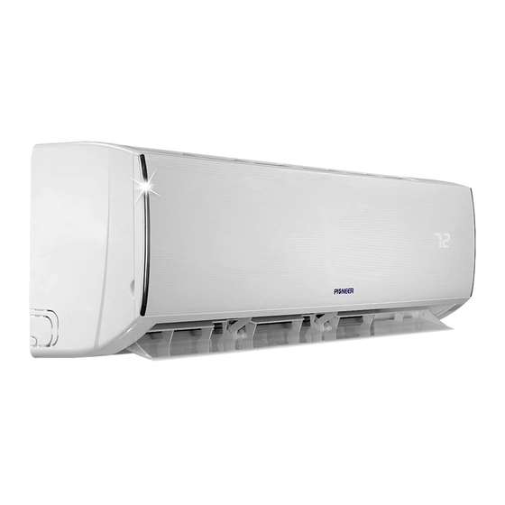
Table of Contents
Advertisement
Advertisement
Table of Contents

Summarization of Contents
Important Notice
How to Order Spare Parts
Procedure and required information for ordering replacement parts for the air conditioning system.
Product Dimensions
Indoor Unit Dimensions
Detailed measurements for the indoor unit, including A, B, and C dimensions for installation planning.
Outdoor Unit Dimensions
Detailed measurements for the outdoor unit, including dimensions D, E, F, G, I, J, and K.
Refrigeration Cycle Diagram
Cooling Only Cycle Diagram
Diagram illustrating the refrigerant flow during cooling operation.
Heat Pump Cycle Diagram
Diagram illustrating the refrigerant flow during heat pump (heating/cooling) operation.
Operation Details
Remote Controller Functions
Explanation of the functions of each button on the remote control for operating the unit.
Remote Control Mode Setting
Instructions on setting the remote controller to Cooling Only or Heat Pump mode.
Electronic Controller Safety Protection
Details on various safety protections implemented in the electronic controller.
"Feel" Mode Operation
Explanation of the 'Feel' mode operation, including temperature settings based on room conditions.
Cooling Mode Operation Details
Details on cooling mode operation, including compressor frequency control and fan speed.
Dry Mode Operation
Description of the dehumidification (Dry) mode operation, including set temperature and fan speed.
Heating Mode Operation
Explanation of the heating mode operation, including frequency control and fan motor control.
Heating Mode Fan Control and Valve Operation
Details on cold air prevention, auto fan control, 4-way valve, and defrosting in heating mode.
Sleep Mode Operation
How to use the Sleep mode for optimized comfort and energy saving during operation.
Emergency and Auto-Restart Functions
Procedure for emergency operation and activating the auto-restart feature.
Protection and Failure Display
Information on error codes, digital LED displays, and how the system indicates faults.
Error and Protection Code Lists
Error List by Failure Type
Table listing various failure types and their corresponding LED and Digital LED error codes.
Protection Display Code List
Table detailing protection types and their corresponding function indicator and digital LED codes.
Outdoor Failure Display Indicators
Explanation of the LED indicators on the outdoor power board for fault status.
Outdoor Power Board Blink Time Codes
List of failures indicated by specific blink patterns on the outdoor power board.
Wiring Diagram
Indoor Unit Wiring Diagram
Schematic showing the electrical connections for the indoor unit of the air conditioner.
Outdoor Unit Wiring Diagram
Schematic showing the electrical connections for the outdoor unit of the air conditioner.
Outdoor Unit Wiring Diagram - Model Variations
Wiring diagram specific to certain models, illustrating outdoor unit connections.
Outdoor Unit Wiring Diagram - Additional Models
Wiring diagram for further outdoor unit models, detailing electrical connections.
Precaution
Safety Rules for Installation
Critical safety guidelines and recommendations for the proper installation of the air conditioner.
Safety Rules for the User
Important safety recommendations for users regarding operation, cleaning, and maintenance.
Safety Rules and Prohibitions
List of actions and conditions to strictly avoid during operation and installation.
Names of Parts
Indoor Unit Components Identification
Identification and labels for the various parts of the indoor unit.
Outdoor Unit Components Identification
Identification and labels for the various parts of the outdoor unit.
Installation Manual
Installation Details: Piping and Cables
Specifications for connecting pipes, refrigerant piping, and connecting cables.
First-Time Installation Guidelines
Recommendations for selecting locations and clearances for indoor and outdoor units.
Mounting Plate and Piping Hole Installation
Steps for installing the mounting plate and drilling the wall for piping.
Indoor Unit Connections
Procedures for indoor unit electrical connections, refrigerant piping, and water drainage.
Refrigerant Piping and Pipe Connections
Detailed steps for connecting refrigerant pipes, including bending and flange creation.
Indoor Unit Water Drainage
Ensuring proper installation and slope of the drain hose for effective water drainage.
Outdoor Unit Connections and Bleeding
Procedures for outdoor unit electrical connections, pipe joining, and refrigerant circuit bleeding.
Troubleshooting
Outdoor Control System Diagram
Schematic illustrating the components and communication within the outdoor control system.
Structure of the ODU PCB
Identification of key components on the Outdoor Unit Printed Circuit Board (ODU PCB).
ODU PCB Connection Details
Detailed connection points and pin assignments on the Outdoor Unit PCB.
Power Supply to Compressor Flow
Diagram showing the flow of power from the supply to the compressor via indoor and outdoor units.
Repairing Display Errors E1 or E2
Troubleshooting steps for errors related to indoor sensor connections or damage.
Repairing Display Error E6
Troubleshooting steps for errors related to the indoor fan motor connection or damage.
Repairing Display Errors E3 or E7
Troubleshooting steps for errors related to outdoor temperature sensors or PCB.
Repairing Display Error E8
Troubleshooting steps for errors related to the outdoor discharge pipe temperature sensor.
Repairing Display Errors E0 or E5
Troubleshooting steps for indoor/outdoor communication damage.
Repairing Display Error EA
Troubleshooting steps for errors related to the current sensor.
Repairing Display Errors E9 or EU
Troubleshooting for outdoor PCB drive circuit damage or voltage sensor issues.
Repairing Display Errors EE or CL
Troubleshooting for EEPROM faults and air filter duty indicators.
Malfunction Check Methods
Procedure for determining defective outdoor unit IPM/compressor using a flowchart.
DC Over Current Error
Troubleshooting DC Over Current Errors
Flowchart for diagnosing and resolving DC over current errors in the air conditioner.
E0, E5 Error
Troubleshooting E0 and E5 Errors
Detailed steps to diagnose and resolve E0 and E5 errors, often related to communication or power.
Thermistor Temperature Characteristics
Indoor and Outdoor Temperature Sensor Data
Tables showing resistance and voltage characteristics of indoor and outdoor temperature sensors.
Outdoor Unit Sensor Characteristics
Detailed resistance and voltage data for outdoor unit sensors across various temperatures.
Outdoor Discharge Pipe Sensor Data
Specific resistance characteristics for the outdoor unit discharge pipe sensor.


Need help?
Do you have a question about the WT009ALFI19HLD and is the answer not in the manual?
Questions and answers