Table of Contents
Advertisement
Quick Links
Pos : 2 /D okumentati on allgemein/Ei nband/Ei nband H andbuch - Dec kbl att ohne Variantenfel d (Standar d) @ 9\mod_1285229289866_0.doc x @ 64941 @ @ 1
Manual
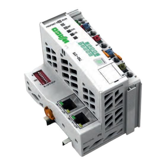
WAGO-I/O-SYSTEM 750
PROFINET IO advanced Fieldbus Coupler
750-375(/xxx-xxx)
2-port switch; 100 Mbit/s;
digital, analog and complex signals
Version 1.1.0
Pos : 3 /Alle Serien (Allgemeine M odul e)/Hinweise z ur Dokumentation/Impres sum für Standardhandbüc her - allg. Angaben, Ansc hriften, Tel efonnummer n und E-Mail-Adres sen @ 3\mod_1219151118203_21.doc x @ 21060 @ @ 1
Advertisement
Chapters
Table of Contents

Related Manuals for WAGO 750-375


Summarization of Contents
Notes about this Documentation
Validity of this Documentation
Specifies the applicability of the documentation to the fieldbus controller and its variants.
Symbols
Explains the meaning of various symbols used for warnings, cautions, and notes.
Abbreviations and Terms
Provides a list of abbreviations and terms used throughout the manual.
Important Notes
Personnel Qualifications
Details the required qualifications for personnel performing operations on Series 750 devices.
Use of the 750 Series in Compliance with Underlying Provisions
Outlines guidelines for the proper and compliant use of the WAGO-I/O-SYSTEM 750.
Safety Advice (Precautions)
Provides essential safety precautions for installing and operating the device.
System Description
Power Supply
Details the power supply requirements, isolation, and connection for the system.
Grounding
Explains the grounding procedures for DIN rails and the grounding function.
Shielding
Provides information on using shielded cables and the WAGO shield connecting system.
Device Description
Fieldbus Coupler Properties
Lists the general specifications and PROFINET IO properties of the fieldbus coupler.
Operating Elements
Describes the device's operating elements like the service interface and DIP switch.
Technical Data
Provides detailed technical specifications including device, system, and supply data.
Mounting
Installation Position
Details the allowed installation positions and requirements for end stops.
Mounting onto Carrier Rail
Explains how to mount components onto a carrier rail and its properties.
Mounting Sequence
Describes the correct order for mounting fieldbus couplers and I/O modules.
Inserting and Removing Devices
Provides instructions for inserting and removing fieldbus couplers and I/O modules.
Connect Devices
Data Contacts/Internal Bus
Describes the internal bus communication and data contacts.
Connecting a Conductor to the CAGE CLAMP®
Details the procedure for connecting conductors using CAGE CLAMP® technology.
Function Description
Device Start-Up and Initialization
Explains the process of device startup, initialization, and status indication.
Configuration Limits
Outlines the minimum and maximum configuration limits for the system.
Flexible Configuration of Digital I/O Modules
Details how to flexibly package digital I/O module data for efficient processing.
Using Fail-Safe I/O Modules (PROFIsafe V2)
Provides information on operating PROFIsafe V2 I/O modules and their features.
Firmware Update
Describes the procedure and requirements for updating the device firmware.
Commissioning
General Procedure
Provides a general overview of the commissioning process for the I/O device.
Perform configuration steps
Lists the specific steps required for system configuration after installation.
Parameterization
Covers parameterization requirements for hardware configuration and data exchange.
PROFINET Connection
Explains how to establish and manage PROFINET connections, including AR and CR.
Web-based Management (WBM)
General Structure of WBM Pages
Describes the layout and navigation of the Web-based Management pages.
Ethernet
Details physical connection to the ETHERNET network and packet statistics.
Diagnostics
Explains how to access and interpret diagnostic messages via the WBM.
Administration
Covers administrative functions within the WBM, such as password management.
Connection Errors
Details potential causes and troubleshooting for WBM connection errors.
Diagnostics
LED Signaling
Explains the meaning of various LEDs on the fieldbus coupler for status indication.
Error Response
Describes how the system responds to fieldbus and internal data bus failures.
PROFINET IO Diagnostics
Details how to perform PROFINET IO diagnostics using record data sets.
Fieldbus Communication
Standard ETHERNET Protocols
Describes standard Ethernet protocols like IP, TCP, HTTP, DCP, LLDP, MRP, and SNMP.
PROFINET IO
Provides a general overview of PROFINET IO, including cabling and device classes.
Addressing
Explains how devices are addressed using MAC addresses and port MAC addresses.
PROFINET Communication Principle
Details PROFINET data traffic types and communication connection establishment.
I/O Modules
Module and Submodule types of the I/O-Modules
Lists and describes various types of digital, analog, and specialty I/O modules.
Parameters of the I/O Modules
Details the parameters and attributes for configuring digital and analog I/O modules.
Use in Hazardous Environments
Marking Configuration Examples
Provides examples of marking configurations for ATEX, IEC-Ex, and NEC 500.
Installation Regulations
Outlines the general rules and regulations for installing equipment in hazardous areas.
Appendix
Module and Submodule types of the I/O-Modules
Lists various types of digital, analog, and specialty I/O modules and their data lengths.
Parameters of the I/O Modules
Details the attributes and descriptions for parameterizing various I/O modules.
Structure of the Standardized Diagnosis Data Sets
Explains the structure of standardized diagnostic data sets and their components.
Need help?
Do you have a question about the 750-375 and is the answer not in the manual?
Questions and answers