Table of Contents
Advertisement
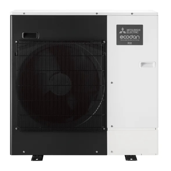
AIR TO WATER HEAT PUMP UNITS
SERVICE MANUAL
<Outdoor unit>
[Model Name]
PUZ-WM50VHA
PUZ-WM60VAA
PUZ-WM85VAA
PUZ-WM85YAA
PUZ-WM112VAA
PUZ-WM112YAA
Salt proof model
PUZ-WM50VHA-BS
PUZ-WM60VAA-BS
PUZ-WM85VAA-BS
PUZ-WM85YAA-BS
PUZ-WM112VAA-BS
PUZ-WM112YAA-BS
PUZ-WM50VHA.UK
[Service Ref.]
PUZ-WM50VHA.UK
PUZ-WM60VAA.UK
PUZ-WM85VAA.UK
PUZ-WM85YAA.UK
PUZ-WM112VAA.UK
PUZ-WM112YAA.UK
PUZ-WM50VHA-BS.UK
PUZ-WM60VAA-BS.UK
PUZ-WM85VAA-BS.UK
PUZ-WM85YAA-BS.UK
PUZ-WM112VAA-BS.UK
PUZ-WM112YAA-BS.UK
R32
CONTENTS
1. REFERENCE MANUAL ································ 2
2. SAFETY PRECAUTION ······························· 3
3. SPECIFICATIONS ······································ 10
4. DATA ··························································· 12
5. OUTLINES AND DIMENSIONS·················· 13
6. WIRING DIAGRAM ····································· 15
7. WIRING SPECIFICATIONS ························ 18
8. REFRIGERANT SYSTEM DIAGRAM ········ 19
9. TROUBLESHOOTING ································ 22
11. DISASSEMBLY PROCEDURE ··················· 66
PARTS CATALOG (OCB727)
March 2020
No. OCH727
Note:
• This manual describes
service data of the outdoor
units only.
Advertisement
Table of Contents
Troubleshooting

Related Manuals for Mitsubishi Electric PUZ-WM112VAA


Summarization of Contents
Reference Manual
Indoor Unit Service Manual
Manuals for indoor units used in air-to-water systems.
Safety Precautions
Always Observe for Safety
Essential safety guidelines to always follow during operations.
Cautions for New Refrigerant (R32)
Specific safety precautions when working with R32 refrigerant.
Service Warnings and Cautions
Warnings for Service
Critical warnings and guidelines for service personnel.
Cautions for Service Operations
Important cautions to observe during service procedures.
Refrigerant Charge Procedures
Guidelines for safely charging refrigerant into the system.
R32 Refrigerant Unit Cautions
Servicing Precautions for R32 Units
Detailed safety measures for servicing R32 refrigerant units.
Repairs to Sealed Components
Specific procedures and considerations for repairing sealed components.
R32 Refrigerant Unit Cautions
Intrinsically Safe Component Repairs
Guidelines for repairing intrinsically safe components.
Cabling and Refrigerant Detection
Precautions for cabling and methods for detecting flammable refrigerants.
Refrigerant Removal and Evacuation
Procedures for safely removing and evacuating refrigerant.
Refrigerant Charging Procedures
Requirements for charging refrigerant, including contamination checks.
Decommissioning Procedures
Essential steps and considerations for decommissioning the unit.
R32 Refrigerant Unit Cautions
Labelling and Recovery Operations
Requirements for labelling equipment and safe refrigerant recovery.
Parts Inspection Schedule
Recommended inspection intervals for unit parts.
Service Tools for R32
Essential Tools for R32 Refrigerant
List of exclusive tools recommended for R32 refrigerant service.
Refrigerant Tools Precautions
Precautions for Reusing Existing Refrigerant Tools
Guidance on using existing tools with R32 refrigerant.
Salt Proof Model Precautions
"-BS" Model Maintenance
Precautions to maintain performance of salt-proof models.
Outdoor Unit Installation Location
Choosing the Installation Location
Guidelines for selecting an appropriate outdoor unit installation site.
Minimum Installation Area Requirements
Ensuring Sufficient Installation Space
Requirements for minimum installation space and ventilation.
Specifications
Outdoor Unit Specifications
Technical specifications for various outdoor unit models.
Available Range Charts
Water Flow Rate vs. Return Water Temp. Range
Charts showing available operating ranges for water flow and return temperature.
Data - Noise Criterion Curves
Octave Band Sound Pressure Level Data
Noise level data presented in octave bands for different models.
Outlines and Dimensions
PUZ-WM50VHA Dimensions
Exterior dimensions and installation space for PUZ-WM50VHA models.
Outlines and Dimensions
PUZ-WM60/85/112VAA Dimensions
Exterior dimensions and installation space for PUZ-WM60/85/112VAA models.
PUZ-WM85YAA Dimensions
Exterior dimensions and installation space for PUZ-WM85YAA models.
PUZ-WM112YAA Dimensions
Exterior dimensions and installation space for PUZ-WM112YAA models.
Wiring Diagram
PUZ-WM50VHA Wiring Schematic
Electrical wiring diagram for PUZ-WM50VHA models.
Wiring Diagram
PUZ-WM60/85VAA Wiring Schematics
Electrical wiring diagrams for PUZ-WM60/85VAA models.
Wiring Diagram
PUZ-WM85/112YAA Wiring Schematics
Electrical wiring diagrams for PUZ-WM85/112YAA models.
Wiring Specifications
Field Electrical Wiring Specifications
Power wiring specifications for different outdoor unit models.
Refrigerant System Diagram
PUZ-WM50VHA Refrigerant Flow
Diagram illustrating the refrigerant flow for PUZ-WM50VHA models.
Refrigerant System Diagram
PUZ-WM60/85VAA Refrigerant Flow
Diagram showing refrigerant flow for PUZ-WM60/85VAA models.
Refrigerant System Diagram
PUZ-WM112VAA/112YAA Refrigerant Flow
Diagram illustrating refrigerant flow for PUZ-WM112VAA/112YAA models.
Troubleshooting Overview
General Troubleshooting Steps
Summary of actions based on self-diagnosis and reoccurrence of issues.
Self-Diagnosis Action Table
Power-On Abnormalities and Actions
Troubleshooting for issues detected upon initial power-up.
Self-Diagnosis Action Table
EA, Eb, EC, EE Error Codes
Diagnosis and actions for communication and connection errors.
Self-Diagnosis Action Table
U1, U2, U3 Error Codes
Troubleshooting for high pressure, discharge, and surface temperature errors.
Self-Diagnosis Action Table
U4, U5, U6, U7, U8 Error Codes
Diagnosis for thermistor, power module, superheat, and fan motor errors.
U9 Error Codes: Overvoltage, Undervoltage, Current
U9 Error Code Details (01, 02, 04, 08)
Troubleshooting for over/undervoltage, current sensor, and power sync errors.
U9 Error Codes: PFC, IGBT, and Other
U9 Error Code Details (10, 20)
Troubleshooting for PFC/IGBT errors and other related issues.
Ud, UE, UF, UH Error Codes
Diagnosis for overheat, abnormal pressure, overcurrent, and current sensor errors.
UL, UP, E0/E4 Error Codes
UL/UP Error Code Details
Troubleshooting for low pressure and compressor overcurrent errors.
E0/E4 Error Code Details
Diagnosis for remote controller communication errors.
E1/E2, E3/E5, E8, E9, EF, Ed Error Codes
Remote Controller and Communication Errors
Troubleshooting for remote controller and communication faults.
P6, P8, PE Error Codes
P6, P8, PE Error Code Details
Diagnosis for freezing, pipe temp, and inlet water temp errors.
Troubleshooting Specific Problems
Remote Controller Display Issues
Troubleshooting common problems with the remote controller display.
Troubleshooting Specific Problems
Unit Operation and Water Drainage Issues
Troubleshooting for unit operation, water drainage, and abnormal sounds.
Remote Controller "PLEASE WAIT" Display Troubleshooting
Diagnosis Flow for "PLEASE WAIT" Display
Step-by-step guide to diagnose persistent "PLEASE WAIT" on the remote controller.
Remote Controller No Display Troubleshooting (Part 1)
Diagnosis Flow for Blank Remote Display (Part 1)
Diagnostic steps for a completely blank remote controller display.
Remote Controller No Display Troubleshooting (Part 2)
Diagnosis Flow for Blank Remote Display (Part 2)
Further diagnostic steps for a blank remote controller display.
Remote Controller No Display Troubleshooting (Part 3)
Diagnosis Flow for Blank Remote Display (Part 3)
Final diagnostic steps for a blank remote controller display.
How to Check Parts
Thermistor Resistance Checks
Procedures for checking thermistor resistance values.
Motor and Valve Resistance Checks
Checking resistance for fan motor, solenoid valve, compressor, and LEV.
How to Check Components
DC Fan Motor and Controller Checks
Procedures for checking DC fan motor and controller board connections.
Pressure Sensor Check
Details on how to check the pressure sensor component.
Thermistor Characteristics
Low Temperature Thermistor Data
Resistance characteristics for low-temperature thermistors.
Medium Temperature Thermistor Data
Resistance characteristics for medium-temperature thermistors.
High Temperature Thermistor Data
Resistance characteristics for high-temperature thermistors.
Linear Expansion Valve (LEV)
LEV Operation Summary and Connection
Overview of LEV operation, pulse signals, and wiring connections.
LEV Operation Details
Explanation of LEV movement, sound, and locking conditions.
Linear Expansion Valve Coil Procedures
Attaching and Detaching the LEV Coil
Steps for removing and installing the linear expansion valve coil.
Test Point Diagrams
Outdoor Controller Circuit Board Test Points
Test points and connections on the outdoor controller circuit board.
Switches, Connectors, and Jumpers
DIP Switch Functions
Explanation of DIP switch functions and settings.
Outdoor Unit Inspection Display
Normal and Abnormal Condition Displays
Indicators for normal and abnormal operating conditions.
Outdoor Unit Inspection Display
Abnormal Condition Error Code Details
Detailed error codes and their corresponding inspection methods.
Outdoor Unit Operation Monitor
Operation Monitor Display Functions
Explains display indicators for operation status and errors.
SW2 Setting Functions (Part 1)
Display Details for SW2 Settings
How SW2 settings control displayed information like temperatures and operating times.
SW2 Setting Functions (Part 2)
Display Details for SW2 Settings (Error Occurring)
How SW2 settings display error-related information.
SW2 Setting Functions (Part 3)
Display Details for SW2 Settings (Temperatures, Capacity)
How SW2 settings display temperature and capacity information.
SW2 Setting Functions (Part 4)
Display Details for SW2 Settings (Heat Sink, Superheat, Defrost)
How SW2 settings display heat sink, superheat, and defrost cycle data.
U9 Error History Display
Displaying U9 error history using SW2 settings.
SW2 Setting Functions (Part 5)
Display Details for SW2 Settings (Error History, Operation Frequency)
How SW2 settings display error history and operating frequency.
SW2 Setting Functions (Part 6)
Display Details for SW2 Settings (Pipe Temp, Superheat, Sub Cool)
How SW2 settings display pipe temperatures and superheat/subcool data.
SW2 Setting Functions (Part 7)
Comp. Surface Temp. Display
Displaying compressor surface temperature using SW2 settings.
Compressor Operating Frequency Control Status
Understanding compressor operating frequency control status via SW2.
Monitoring Operation Data via Remote Controller
Request Code List for Operation Data
List of request codes to monitor various operation data points.
Monitoring Operation Data via Remote Controller
Request Code List for Operation Data (Cont.)
Continued list of request codes for monitoring operation data.
Monitoring Operation Data via Remote Controller
Request Code List for Operation Data (Cont.)
Continued list of request codes for monitoring operation data.
Detail Contents in Request Codes
Operation State Details (Request Code "0")
Detailed breakdown of operation states and relay outputs.
Outdoor Unit Control State Details (Request Code "51")
Details on outdoor unit control states and their meanings.
Compressor Frequency Control State Details (Request Code "52")
Details on compressor frequency control states.
Fan Control State Details (Request Code "53")
Details on fan control states and correction values.
Actuator Output State and Error Content
Actuator Output State Details (Request Code "54")
Details on actuator output states for various components.
U9 Error Content Details (Request Code "55")
Breakdown of U9 error content and detected errors.
Outdoor Unit Setting Information
Capacity Setting Display (Request Code "70")
Display of outdoor unit capacity settings using request codes.
Setting Information Display (Request Code "71")
Details on setting information like defrost mode and phase.
Disassembly Procedure
Removing Service, Top, and Cover Panels
Steps to remove exterior panels for access.
Removing the Fan Motor (MF1)
Procedure for safely removing the fan motor.
Removing the Electrical Parts Box
Steps to remove the electrical parts box assembly.
Disassembly Procedure
Removing Thermistors (TH6, TH7, TH3)
Steps to remove 2-phase pipe, ambient, and liquid thermistors.
Removing Discharge and Surface Thermistors (TH4, TH33)
Procedure to remove discharge and compressor surface thermistors.
Disassembly Procedure
Removing 4-Way Valve Coil, LEV Coil, and High Pressure Switch Wires
Steps to remove valve coils and high pressure switch wires.
Removing 4-Way Valve, LEV, High Pressure Switch, Pressure Sensor
Procedure to remove 4-way valve, LEV, high pressure switch, and sensor.
Disassembly Procedure
Removing High Pressure Switch (63H)
Steps to remove the high pressure switch.
Removing Pressure Sensor (63HS)
Procedure to remove the pressure sensor.
Removing the Compressor (MC)
Steps to remove the compressor and its associated parts.
Disassembly Procedure
Removing the Receiver
Steps to remove the refrigerant receiver.
Removing the Plate Heat Exchanger
Procedure to remove the plate heat exchanger.
Removing Pressure Relief Valve and Gasket
Steps to remove the pressure relief valve and gasket.
Disassembly Procedure
Disassembling Electrical Parts Box (V Model)
Detailed steps for disassembling the electrical parts box for V model units.
Disassembling Electrical Parts Box (Y Model)
Detailed steps for disassembling the electrical parts box for Y model units.
Disassembly Procedure
Removing Service and Top Panels (112VAA/112YAA Models)
Steps to remove service and top panels for specific models.
Removing Fan Motor (MF1) (112VAA/112YAA Models)
Procedure to remove the fan motor for specific models.
Removing Electrical Parts Box (112VAA/112YAA Models)
Steps to remove the electrical parts box for specific models.
Disassembly Procedure
Disassembling Electrical Parts Box (V Model)
Detailed steps for disassembling the electrical parts box for V models.
Disassembling Electrical Parts Box (Y Model)
Detailed steps for disassembling the electrical parts box for Y models.
Disassembly Procedure
Removing Thermistor <2-Phase Pipe> (TH6)
Steps to remove the 2-phase pipe thermistor.
Removing Thermistor (TH7)
Steps to remove the ambient thermistor.
Removing Thermistor (TH3)
Steps to remove the liquid thermistor.
Disassembly Procedure
Removing Discharge and Surface Thermistors (TH4, TH33)
Steps to remove discharge and surface thermistors.
Removing Plate Hex Liquid Thermistor (TH34)
Steps to remove the plate hex liquid thermistor.
Disassembly Procedure
Removing Valve Coils and High Pressure Switch Wires
Steps to remove valve coils and high pressure switch wires.
Removing 4-Way Valve, LEV, High Pressure Switch, Pressure Sensor
Procedure to remove valve, LEV, pressure switch, and sensor.
Disassembly Procedure
Removing the Compressor (MC)
Steps to remove the compressor and its associated parts.
Removing the Receiver
Steps to remove the refrigerant receiver.
Disassembly Procedure
Removing Plate Heat Exchanger
Steps to remove the plate heat exchanger.
Removing Reactor (ACL)
Steps to remove the reactor (ACL).
Removing Pressure Relief Valve and Gasket
Steps to remove the pressure relief valve and gasket.
Disassembly Procedure
Removing Service and Top Panels (112VAA/112YAA Models)
Steps to remove service and top panels for specific models.
Removing Fan Motor (MF1) (112VAA/112YAA Models)
Procedure to remove the fan motor for specific models.
Removing Electrical Parts Box (112VAA/112YAA Models)
Steps to remove the electrical parts box for specific models.
Disassembly Procedure
Disassembling Electrical Parts Box (V Model)
Detailed steps for disassembling the electrical parts box for V models.
Disassembling Electrical Parts Box (Y Model)
Detailed steps for disassembling the electrical parts box for Y models.
Disassembly Procedure
Removing Thermistor <2-Phase Pipe> (TH6)
Steps to remove the 2-phase pipe thermistor.
Removing Thermistor (TH7)
Steps to remove the ambient thermistor.
Removing Thermistor (TH3)
Steps to remove the liquid thermistor.
Disassembly Procedure
Removing Discharge and Surface Thermistors (TH4, TH33)
Steps to remove discharge and surface thermistors.
Removing Plate Hex Liquid Thermistor (TH34)
Steps to remove the plate hex liquid thermistor.
Disassembly Procedure
Removing Valve Coils and High Pressure Switch Wires
Steps to remove valve coils and high pressure switch wires.
Removing 4-Way Valve, LEV, High Pressure Switch, Pressure Sensor
Procedure to remove valve, LEV, pressure switch, and sensor.
Disassembly Procedure
Removing the Compressor (MC)
Steps to remove the compressor and its associated parts.
Removing the Receiver
Steps to remove the refrigerant receiver.
Disassembly Procedure
Removing Plate Heat Exchanger
Steps to remove the plate heat exchanger.
Removing Reactor (ACL)
Steps to remove the reactor (ACL).
Removing Pressure Relief Valve and Gasket
Steps to remove the pressure relief valve and gasket.
Need help?
Do you have a question about the PUZ-WM112VAA and is the answer not in the manual?
Questions and answers