
Related Manuals for Eaton Moeller MFD-80


Summary of Contents for Eaton Moeller MFD-80
- Page 1 Display/Operator System for CANopen MFD-CP4-CO, MFD-80 Hardware and Engineering 05/08 AWB2528-1611en...
- Page 2 All brand and product names are trademarks or registered trademarks of the owner concerned. published 2008, edition date 05/08 © 2008 by Moeller GmbH, 53105 Bonn Author: Heribert Einwag Editor: Thomas Kracht Translator: Dominik Kreuzer All rights reserved, including those of the translation. No part of this manual may be reproduced in any form (printed, photocopy, microfilm or any other process) or processed, duplicated or distributed by means of electronic...
- Page 3 Danger! Dangerous electrical voltage! Before commencing the installation • Disconnect the power supply of the device. • Suitable safety hardware and software measures should be implemented for the • Ensure that devices cannot be accidentally I/O interface so that a line or wire breakage restarted.
- Page 4 • Measures should be taken to ensure the • Wherever faults in the automation system proper restart of programs interrupted may cause damage to persons or property, after a voltage dip or failure. This should external measures must be implemented to not cause dangerous operating states even ensure a safe operating state in the event for a short time.
-
Page 5: Table Of Contents
05/08 AWB2528-1611en Contents About this manual Intended users Additional manuals Reading conventions About the Display/Operator System Overview Task – Display functions – Operator functions Setup – Display/operating unit – Communication module Installation Mounting – Fitting the protective membrane – Mounting the protective cover –... - Page 6 05/08 AWB2528-1611en Appendix Dimensions – MFD-80.. display/operating unit – MFD-80-XM protective diaphragm – MFD-80-XS protective cover – Communication module MFD-CP4-CO Technical data – General ambient conditions – MFD-80.. display/operating unit – MFD-XM-80 protective diaphragm – MFD-XS-80 protective cover – Communication module MFD-CP4-CO Index...
-
Page 7: About This Manual
05/08 AWB2528-1611en About this manual This manual describes the installation, commissioning and operation of the display/operating system. Intended users This display/operator device must only be mounted and connected by qualified electrical personnel or a person familiar with the electrical installation. A specialist knowledge of electrical engineering is needed for commissioning. -
Page 8: Reading Conventions
05/08 AWB2528-1611en About this manual Reading conventions Symbols used in this manual have the following meanings: Indicates instructions to be followed. Caution! Warns of the risk of material damage. Warning! Warns of the possibility of serious damage and slight injury. Danger! Indicates the risk of major damage to property, or serious or fatal injury. -
Page 9: About The Display/Operator System
05/08 AWB2528-1611en About the Display/Operator System Overview The display/operator system consists of the following indi- vidual components: • MFD-80.. display/operator unit • Communication module MFD-CP4-CO • CANopen connection cable for connecting a Moeller PLC (such as EU4A-RJ45-CAB2 for connecting an EC4P). EC4P EU4A-RJ45-CAB2 MFD-CP4-CO... -
Page 10: Display Functions
05/08 AWB2528-1611en About the Display/Operator System Danger! The display/operator system must only be run if it is prop- erly mounted and installed: • The installation must comply with regulations for elec- tromagnetic compatibility (EMC). • MFD-CP4-CO is designed to be installed in an enclo- sure, switch cabinet or distribution board. -
Page 11: Task
05/08 AWB2528-1611en Task Boiler 23 Set temp. 75°C Act temp. 34°C Heat! Figure 2: Example of a basic page • Start page A user-defined 4-line start page can also be loaded in addi- tion to the basic pages. This is stored retentively on the display device. -
Page 12: Display/Operating Unit
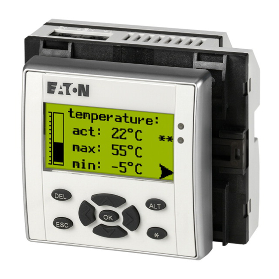
05/08 AWB2528-1611en About the Display/Operator System ftp://ftp.moeller.net/AUTOMATION/DOWNLOAD/APPLICATION-EXAMPLES-NOTES- MODULES/EASY_HMI/MFD-CP4-CO/. Setup Display/operating unit Figure 4: Display/operating unit a DEL button b Graphic display c ALT button d LEDs for signalling e Mode button f Right, down cursor buttons g OK button h Left, up cursor buttons i ESC button Key to part numbers MFD - 80 - B... -
Page 13: Setup
05/08 AWB2528-1611en Setup Communication module Figure 5: Communication module a Power supply b CANopen interface Key to part numbers MFD - CP4 - CO CANopen CP4 = CPU Multi-function display... - Page 14 05/08 AWB2528-1611en...
-
Page 15: Installation
05/08 AWB2528-1611en Installation The MFD-CP4-CO must only be installed and connected up by trained electricians or a person familiar with the installa- tion of electrical equipment. The MFD-CP4-CO is installed in the following order: • Mounting, • Connecting the serial interface, •... -
Page 16: Fitting The Protective Membrane
05/08 AWB2528-1611en Installation Fitting the protective membrane For special applications such as in the food industry, the keypad must be protected against the ingress of dust, liquids etc. In this case fit the protective membrane over the display/ operator unit. Fit the protective membrane before mounting the display/ operator unit. -
Page 17: Mounting The Protective Cover
05/08 AWB2528-1611en Mounting Figure 8: Correct position of the protective membrane If the protective membrane has to be replaced, the display/ operator unit has to be removed. Replace the membrane and refit the device. Mounting the protective cover The protective cover is provided for using the device in aggressive environments. - Page 18 05/08 AWB2528-1611en Installation First remove the front frame before mounting. Figure 9: Removing the front frame The protective cover can be mounted in two different posi- tions. Choose the position that is most suitable for the applica- tion at hand and your requirements. Figure 10: Position of the protective cover...
- Page 19 05/08 AWB2528-1611en Mounting Mount the protective cover as shown in the figure. Figure 11: Mounting the protective cover Sealing the protective cover Figure 12: Sealing the protective cover The grip handle of the protective cover is provided with holes that can be used in any mounting position. You can fit a wire or similar material through these holes in order to seal the cover.
-
Page 20: Mounting The Display/Operating Unit (Front Mounting)
05/08 AWB2528-1611en Installation Mounting the display/operating unit (front mounting) The protective membrane or the protective cover must be fitted beforehand. Drill and punch out two 22.5 mm diameter holes in the front plate. The diameter is the same as is normally required for control circuit devices. - Page 21 05/08 AWB2528-1611en Mounting Fit the display/operator unit in the punched fixing holes. Figure 14: Mounting the display/operator unit Tighten the display/operator unit with the M22-MS combi- nation box spanner (a figure 15). The tightening torque must be between 1.2 and 2 Nm Ensure that the correct torque is used.
-
Page 22: Removing The Display/Operating Unit (Front Mounting)
05/08 AWB2528-1611en Installation Figure 15: Screw fastening the display/operating unit Figure 16: Rear of the mounted display/operator unit Removing the display/operating unit (front mounting) Unscrew the fixing element and remove the display/oper- ator unit. -
Page 23: Mount Communication Module
05/08 AWB2528-1611en Mounting Mount communication module Figure 17: Mount communication module... -
Page 24: Removing The Communication Module
05/08 AWB2528-1611en Installation Removing the communication module Use a screwdriver with a 100 x 3.5 mm slot width. Insert the screwdriver into the lug of the fixing shaft catch. Lever out the slide catch. Pull out the communication module from the fixing shafts Figure 18: Releasing the fixing shaft Connections Terminals... -
Page 25: Connecting The Supply Voltage
05/08 AWB2528-1611en Connections Connecting the supply voltage The required connection data for the MFD-CP4-CO is provided in the section “Technical data”, page 29. DC power supply MFD-CP4-CO L01+ L02+ L01– > 1 A U e = 24 V H (20.4 – 28.8 V H) I e = 150 mA 0.6 x 3.5 x 100 Figure 19: Power supply on the MFD... -
Page 26: Connecting The Connection Cable
05/08 AWB2528-1611en Installation Connecting the connection cable a figure 20 and 21 or 22 Remove the interface cover carefully Use a screwdriver to press down the recess next to the terminal and connect the wires of the connection cable to the terminals in the order stated . - Page 27 05/08 AWB2528-1611en Connections MFD-CP4-CO to EC4P You can use the EU4A-RJ45-CAB2 cable to connect the MFD-CP4-CO to an EC4P. grün CAN_L CAN_H schwarz CAN_L CAN_H RJ45 Figure 21: Connecting the MFD-CP4-CO to EC4P Connector type: 6-pole cage clamp terminal block, cable connections: up to 0.5 mm...
- Page 28 05/08 AWB2528-1611en Installation MFD-CP4-CO to XC200, XC121 CAN_L CAN_H CAN_L CAN_H Figure 22: Connecting MFD-CP4-CO to XC121 or XC200 Connector type: 6-pole cage clamp terminal block, cable connections: up to 0.5 mm Bus terminating resistors 120 O bus terminating resistors must be used at the ends of the network: CAN_L CAN_H...
-
Page 29: Setting And Commissioning The Device
05/08 AWB2528-1611en Setting and commissioning the device Settings You can display and modify the station address (node ID), baud rate, backlight and contrast via the MFD80 display. Press the DEL and ALT buttons simultaneously to call up the Setup menu. NodeID : 2 Baud rate:125 Backlight:100%... -
Page 30: Initial Commissioning
05/08 AWB2528-1611en Setting and commissioning the device Initial Commissioning Danger! The display/operator system must only be run if it is prop- erly mounted and installed: • The installation must comply with regulations for elec- tromagnetic compatibility (EMC). • MFD-CP4-CO is designed to be installed in an enclo- sure, switch cabinet or distribution board. - Page 31 05/08 AWB2528-1611en Appendix Dimensions MFD-80.. display/operating unit 28.25 g0.2 28.25 13.7 86.5 MFD-80-XM protective diaphragm 22.5 88.5...
- Page 32 05/08 AWB2528-1611en Appendix MFD-80-XS protective cover 86.5 Communication module MFD-CP4-CO 36.2 22.5 22.5...
- Page 33 05/08 AWB2528-1611en Dimensions Technical data General ambient conditions Climatic conditions (damp heat constant to IEC 60068-2-78; cyclical to IEC 60068-2- (cold to IEC 60068-2-1, heat to IEC 60068-2-2) Operating ambient temperature °C, (°F) –25 to 55, (–13 to 131) Installed horizontally/vertically Condensation Prevent condensation by means of suitable measures...
- Page 34 05/08 AWB2528-1611en Appendix Electromagnetic compatibility (EMC) Electrostatic discharge (ESD), (IEC/EN 61000-4-2, severity level 3) Air discharge Contact discharge Electromagnetic fields (RFI), (IEC/EN 61000-4-3) Radio interference suppression (EN 55011, EN 55022), limit class Fast transient burst (IEC/EN 61000-4-4, severity level 3) Supply cables Signal cables High energy pulses (Surge) MFD (IEC/EN 61000-4-5,...
- Page 35 05/08 AWB2528-1611en Dimensions MFD-80.. display/operating unit Front dimensions W x H x D With buttons 86.5 x 86.5 x 21.5 inches 3.41 x 3.41 x 0.85 Without buttons 86.5 x 86.5 x 20 inches 3.41 x 3.41 x 0.79 Overall dimensions with fixing shaft W x H x D With buttons 86.5 x 86.5 x 43 inches...
- Page 36 05/08 AWB2528-1611en Appendix Operating buttons Number Pushbutton illumination (LED) Number Colour green MFD-XM-80 protective diaphragm Dimensions W x H x D 88 x 88 x 25 inches 3.46 x 3.46 x 0.98 Weight 0.055 Mounting Is fitted over the display/keypad (with Titan front ring) MFD-XS-80 protective cover Dimensions W x H x D...
- Page 37 05/08 AWB2528-1611en Dimensions Communication module MFD-CP4-CO Dimensions 75 x 58 x 36.2 W x H x D inches 2.95 x 2.28 x 1.43 Weight 0.362 Mounting Plug-fitted to the display fixing shaft Power supply Rated voltage Rated value V DC, 24, (+20, –15) Permissible range V DC...
- Page 38 05/08 AWB2528-1611en...
- Page 39 05/08 AWB2528-1611en Index Backlight .............25 Baud rate adjustment ..........8 Baud rates ............25 Bus terminating resistors ........24 Cable protection ..........21 CANopen .............33 CANopen interface, Position on the device ..10 Changing parameters ..........25 Commissioning ............26 Communication module Mounting .............19 Technical data ..........33 Connection Cross sections ..........30 Supply voltage ..........21...
- Page 40 05/08 AWB2528-1611en Index HMI device ............9 Initial Commissioning ..........26 Installation -> Mounting Insulation resistance ..........30 Keypad Position on the device ........9 Minimum clearances when mounting in a control panel ............11 Mounting Communication module .......19 Display/Operating unit .........16 Protective cover ...........13 Protective diaphragm ........12 Node ID ..............25 Node-Id setting .............8...
- Page 41 05/08 AWB2528-1611en Index Reverse polarity protection ........21 Sealing the protective cover .........15 Settings ...............25 Setup menu ............25 Software version ..........25 Station address ............25 Supply voltage, Connecting .........21 Technical data .............29 Tools ..............30 Type code Communication module .......10 Display/operator unit ........9...
Need help?
Do you have a question about the Moeller MFD-80 and is the answer not in the manual?
Questions and answers