
Related Manuals for Lamtec AEC-VS


Summarization of Contents
1 Important Information about the Manual
1.1 Validity of these Instructions
Specifies the manual's validity for the CMS burner control system and software versions.
1.2 References to Other Documents
Lists additional available information for the CMS from other documents.
1.3 Standards, Directives and Approvals
Details the harmonized European, USA, and Canadian standards and directives the CMS complies with.
1.4 Abbreviations
Defines abbreviations used throughout the manual for technical terms and components.
2 Safety
2.1 Classification of the Safety Instructions and Warnings
Explains the symbols used for safety information and operator responsibilities.
2.2 Target Group
Defines the intended audience for the manual and prerequisites for safe operation.
2.3 Product-specific Dangers
Highlights specific safety risks and precautions related to the CMS device and its operation.
2.3.1 Mounting Notes
Provides essential guidelines for safely mounting the CMS device and its components.
2.3.2 Installation Notes
Details critical notes for safely installing electrical components and wiring the CMS system.
2.3.3 Commissioning Notes
Outlines essential safety considerations and documentation requirements during the commissioning phase.
2.3.3.1 Electronic Ratio Control
Ensures proper burner operation via excess air control and actuator checks.
2.3.3.2 Basic Device
Lists items to check before commissioning the basic device, including valve assignments and flame sensor function.
2.3.3.3 Parameter Settings
Checks parameter settings, especially safety and pre-purge times, and valve leakage control.
2.3.3.4 FFS/ION/Terminal - Flame Tolerance Time
Explains flame tolerance time calculation and factors affecting response time.
2.3.4 Electrical Connection Flame Sensor
Details requirements for connecting approved flame sensors and minimizing signal transmission losses.
2.3.5 CO/O2 Measuring Systems
Lists compatible CO and O2 measuring systems that can be connected to the CMS.
2.3.6 Acceptance and Inspection
Outlines checks for device labels, safety parameters, safe combustion, and actuator assignments.
2.3.7 Components/Devices of External Manufacturers
Specifies insulation requirements for third-party devices connected to the CMS communication interface.
3 System Description
3.1 Brief Description
Provides an overview of the CMS as a modular burner control system and its adjustable features.
3.2 Digital Input/Output Functions
Explains the digital inputs and outputs available on the CMS and their functions.
3.2.1 Digital Inputs
Details the list of digital inputs (logic signals) and their descriptions.
3.2.2 Digital Outputs
Lists the digital outputs available on the CMS and their functions.
3.2.3 Assignment of Input/Output Functions
Explains how input and output functions are assigned using the I/O matrix in the CMS remote software.
3.2.4 Chain Functions
Describes the 10 signal chains for linking input signals, configurable via the I/O matrix.
3.2.5 Curve Set Selection
Explains the mechanism for selecting predefined curve sets for burner control.
3.3 Analogue Inputs/Outputs
Details the types of analogue signals supported for inputs and outputs.
3.3.1 Analogue Inputs
Lists physical signals for analogue inputs and examples of predefined functions.
3.3.2 Analogue outputs
Lists physical signals for analogue outputs and examples of functions.
3.4 Functional Description of the Modules
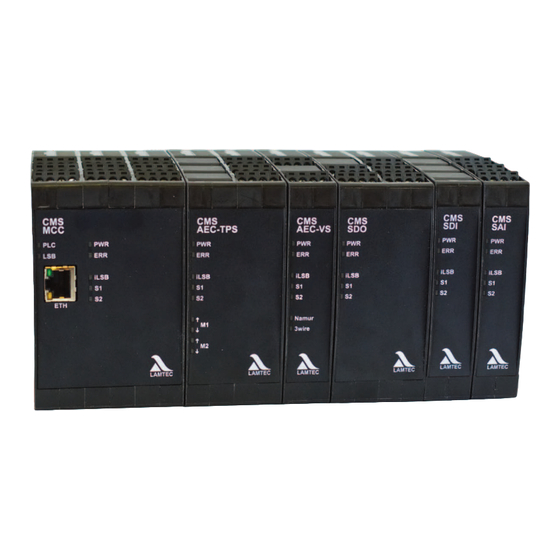
Describes the functionality of various CMS modules like MCC, AEC-TPS, AEC-VS, SDI, SDO, SAI.
MCC
Describes the MCC module as a burner sequencer with communication interfaces and I/O options.
AEC-TPS
Details the AEC-TPS module for controlling two three-point step servomotors with potentiometer feedback.
AEC-VS
Explains the AEC-VS module for controlling frequency inverters and actuators with 4-20mA interface.
SDI
Describes the SDI module, providing 8 safe digital inputs.
SDO
Details the SDO module, providing 8 safe digital outputs.
SAI
Explains the SAI module with 6 non-safe/3 safe analogue inputs and 2 pulse inputs.
UI400
Describes the UI400 as a compact HMI for fault status, curve programming, and system queries.
GUI6xx
Details GUI6xx touch panels for curve programming, parameter setting, and system queries.
3.5 Life Cycle
Provides information on the designed lifetime of the CMS system in burner start-up cycles and years.
4 CMS Components
4.1 MCC – Master Control Component (burner module)
Describes the MCC module, its safety features, and technical data.
4.1.1 For Your Safety
Highlights safety measures for the MCC, including password protection and using approved flame sensors.
4.1.2 Technical Data
Presents the technical specifications for the MCC module, including dimensions, supply voltage, and inputs/outputs.
4.1.3 Functional Description
Explains the MCC's use as a standalone burner sequencer and its configurable I/O matrix.
4.1.4 LEDs
Details the function of each LED indicator on the MCC module for status and fault indication.
4.1.5 Terminal Assignment
Provides diagrams showing the terminal assignments for MCC modules based on voltage variants.
4.1.6 Connection Diagram
Illustrates the wiring and connection diagram for the MCC module, including safe inputs and outputs.
4.1.7 Interfaces
Details the Ethernet/Modbus TCP, LAMTEC SYSTEM BUS (LSB), and PROFINET interfaces for the MCC.
4.2 AEC-TPS – Actuator Extension Component Three Point Step
Introduces the AEC-TPS module for three-point step actuators and its safety considerations.
4.2.1 For Your Safety
Highlights safety precautions for the AEC-TPS module, including feedback potentiometers and motor voltage induction.
4.2.2 Technical Data
Presents the technical specifications for the AEC-TPS module, including power supply and motor outputs.
4.2.3 Functional Description
Explains how AEC-TPS controls DPS servomotors for valve positioning and its configuration parameters.
4.2.4 LEDs
Details the function of each LED indicator on the AEC-TPS module for status and fault indication.
4.2.5 Terminal Assignment
Provides diagrams showing terminal assignments for AEC-TPS modules based on voltage variants.
4.2.6 Connection Diagram
Illustrates the wiring and connection diagram for the AEC-TPS module, showing failsafe communication via iLSB.
4.2.7 Interfaces
Specifies that failsafe communication is via iLSB for the AEC-TPS module.
4.2.8 Approved Actuators
Lists approved actuators for use with the AEC-TPS module and mentions future servo motors.
4.3 AEC-VS – Actuator Extension Component Variable Speed
Introduces the AEC-VS module for variable speed actuators and its safety considerations.
4.3.1 For Your Safety
Highlights safety precautions for AEC-VS, including feedback signals and SELV connections.
4.3.2 Technical Data
Presents technical specifications for AEC-VS, including power supply, signal inputs, and outputs.
4.3.3 Terminal Assignment
Provides diagrams showing terminal assignments for AEC-VS modules based on voltage variants.
4.3.4 Functional Description
Explains AEC-VS features like pulse inputs, analogue inputs/outputs, and channel configuration.
4.3.5 LEDs
Details the function of each LED indicator on the AEC-VS module for status and fault indication.
4.3.6 Connection Diagram
Illustrates the wiring and connection diagram for the AEC-VS module, showing failsafe communication via iLSB.
4.3.7 Interfaces
Specifies that failsafe communication is via iLSB for the AEC-VS module.
4.3.8 Sensors Suitable for CMS
Lists Namur and 3-wire sensors tested and approved for use with the CMS.
4.4 SDI - Safe Digital Input
Introduces the SDI module for safe digital inputs and its safety considerations.
4.4.1 For Your Safety
Refers to Chapter 2 Safety for safety instructions related to the SDI module.
4.4.2 Technical Data
Presents technical specifications for the SDI module, including power supply, digital inputs, and environmental conditions.
4.4.3 Terminal Assignment
Provides diagrams showing terminal assignments for SDI modules based on voltage variants.
4.4.4 Functional Description
Explains that the SDI module provides failsafe digital inputs to expand the CMS system's I/O.
4.4.5 LEDs
Details the function of each LED indicator on the SDI module for status and fault indication.
4.4.6 Connection Diagram
Illustrates the wiring and connection diagram for the SDI module, showing failsafe communication via iLSB.
4.4.7 Interfaces
Specifies that failsafe communication is via iLSB for the SDI module.
4.5 SDO - Safe Digital Output
Introduces the SDO module for failsafe digital outputs and its safety considerations.
4.5.1 For Your Safety
Refers to Chapter 2 Safety for safety instructions related to the SDO module.
4.5.2 Technical Data
Presents technical specifications for the SDO module, including power supply, digital outputs, and environmental conditions.
4.5.3 Terminal Assignment
Provides diagrams showing terminal assignments for SDO modules based on voltage variants.
4.5.4 Functional Description
Explains that the SDO module provides failsafe digital outputs to enhance the CMS system.
4.5.5 LEDs
Details the function of each LED indicator on the SDO module for status and fault indication.
4.5.6 Connection Diagram
Illustrates the wiring and connection diagram for the SDO module, showing failsafe relay outputs.
4.5.7 Interfaces
Specifies that failsafe communication is via iLSB for the SDO module.
4.6 SAI - Safe Analogue Input
Introduces the SAI module for safe analogue inputs and its safety considerations.
4.6.1 For Your Safety
Refers to Chapter 2 Safety for safety instructions related to the SAI module.
4.6.2 Technical Data
Presents technical specifications for the SAI module, including power supply, current draw, and environmental conditions.
4.6.3 Terminal Assignment
Provides diagrams showing terminal assignments for SAI modules.
4.6.4 Functional Description
Explains SAI terminal configuration and parameter settings for analogue inputs.
4.6.5 LEDs
Details the function of each LED indicator on the SAI module for status and fault indication.
4.6.6 Connection Diagram
Illustrates the wiring and connection diagram for the SAI module, showing failsafe communication via iLSB.
4.6.7 Interfaces
Details the configuration options for SAI module inputs (non-failsafe, failsafe linked/not linked).
4.7 UI400 - User Interface
Introduces the UI400 as a compact HMI for system operation and monitoring, and its safety precautions.
4.7.1 For Your Safety
Refers to Chapter 2 Safety for safety instructions related to the UI400.
4.7.2 Technical Data
Presents technical specifications for the UI400, including supply voltage and power consumption.
4.7.3 Functional Description
Explains the UI400's role as an HMI for configuration and monitoring of the burner.
4.7.4 Pin Assignment
Shows the pin assignment for the UI400's terminal connection.
4.7.5 Interfaces
Specifies that communication for the UI400 is via LSB with the CMS.
4.8 Graphic User Interface - GUI607/GUI610/GUI615
Introduces GUI6xx models as touch-sensitive panels for system visualization and operation, with safety precautions.
4.8.1 For Your Safety
Details safety precautions for GUI6xx, emphasizing SELV voltage and CMS 24V output usage.
4.8.2 Technical Data
Presents technical specifications for GUI607, including display size, touch screen type, and CPU.
4.8.2.1 GUI607
Provides detailed technical specifications for the GUI607 graphical user interface.
4.8.2.2 GUI615
Presents detailed technical specifications for the GUI615 graphical user interface.
4.8.3 Functional Description
Explains the GUI6xx models as HMIs for burner configuration and monitoring.
4.8.4 Connection Diagram
Illustrates connection assignments for GUI607, including power supply, USB, and Ethernet.
4.8.5 Interfaces
Details the interfaces used for GUI6xx, including Ethernet and CAN-Bus.
4.9 Router
Covers router usage for Ethernet-based communication and IT security guidelines.
4.9.1 For Your Safety
Highlights IT security guidelines and unauthorized access prevention when connecting CMS to LAN/WLAN.
4.9.2 Functional Description
Recommends specific routers for Ethernet communication and alternative WLAN communication.
5 Functional Description with Process Diagrams
5.1 Basic Burner Sequencer Functionality
Presents example process diagrams for basic burner sequencing, emphasizing special point settings.
5.1.1 Default Process Flow for Gas Modulating with Pilot Burner
Shows the process sequence chart for gas modulating burners with a pilot burner.
5.1.2 Default Process Flow for Gas Modulating Without Pilot Burner
Illustrates the process sequence chart for gas modulating burners without a pilot burner.
5.1.3 Default Process Flow for Oil Modulating With Pilot Burner
Presents the process sequence chart for oil modulating burners with a pilot burner.
5.1.4 Default Process Flow for Oil Modulating Without Pilot Burner
Shows the process sequence chart for oil modulating burners without a pilot burner.
5.2 Additional Burner Sequencer Functionality
Describes additional functionalities for the burner sequencer, including start without pre-purge.
5.2.1 Start Without Pre-Purge
Explains the 'Start Without Pre-Purge' function, including requirements and digital inputs/outputs.
5.2.1.1 Requirements
Lists requirements for activating 'Start Without Pre-Purge', including local regulations and system configuration.
5.2.1.2 Required Inputs/Outputs
Specifies the digital inputs required for the 'pre-purge suppression' function.
5.2.1.3 Required Parameters
States that the 'Start Without Pre-Purge' function does not require special parameters.
5.2.1.4 Functional Description
Describes how pre-purge suppression works via an external signal.
5.2.2 Standby Mode
Details the standby mode function, including requirements, inputs/outputs, and parameters.
5.2.2.1 Requirements
Lists requirements for standby mode, such as pilot valve, pilot flame, and fuel supply.
5.2.2.2 Required Inputs/Outputs
Specifies inputs (standby active, pilot air monitor) and outputs (pilot valve, pilot air fan) for standby mode.
5.2.2.3 Required Parameters
Lists parameters for standby mode, including standby mode and pilot air operation settings.
5.2.2.4 Functional Description
Illustrates the process sequence chart for standby operation of the burner.
5.2.3 Purging the Fuel Train
Explains the function of purging the oil gun and gas train, including requirements and inputs/outputs.
5.2.3.1 Requirements
Specifies the requirement to configure the 'Purge oil gun' special curve point.
5.2.3.2 Required Inputs/Outputs
Lists required inputs/outputs for oil gun purging: purge valve and atomiser steam valve.
5.2.3.3 Required Parameters
Lists parameters related to purging, including extension of safety time and duration.
5.2.3.4 Purging After Operation
Describes the 'Purging After Operation' process, including valve actions and sequence control.
5.2.3.5 Purging with Digital Input
Explains 'Purging by digital input' requirements, including burner state and input signal.
5.2.3.6 Purging Oil Gun during Standby Operation and Fuel Changeover by Pilot Burner
Describes purging the oil gun during standby and fuel changeover modes.
5.2.3.7 Operating Modes for the 'Purging Fuel Train Function
Lists the operating modes for the 'Purging Fuel Train Function', including after operation and standby.
5.2.4 Pilot Burner - Continuous Operation
Details continuous operation of the pilot burner, including requirements and inputs/outputs.
5.2.4.1 Requirements
States the requirement for the 'Pilot Burner - Continuous Operation' function to be mapped.
5.2.4.2 Required Inputs/Outputs
Specifies the 'Pilot burner operation' input for continuous pilot burner operation.
5.2.4.3 Required Parameters
Lists parameters for pilot burner continuous operation, including control and monitoring options.
5.2.4.4 Process Sequence Chart: Pilot Burner Continuous Operation
Illustrates the process sequence chart for continuous pilot burner operation.
5.2.5 CPI/POC - Closed Position Indication/Proof of Closure
Explains CPI/POC function for monitoring main valve closed position and its requirements.
5.2.5.1 Requirements
States that gas valves must be equipped with limit switches (CPI/POC) for this function.
5.2.5.2 Required Inputs/Outputs
Specifies CPI/POC inputs for main valves and refers to digital input descriptions.
5.2.5.3 Required Parameters
Lists parameters related to CPI/POC and burner sequencer special functions.
5.2.5.4 Functional Description
Describes how CPI/POC input monitors main valve position and initiates shutdown on incorrect switching.
5.2.6 Valve Leakage Test
Explains the valve leakage test, including requirements and parameters.
5.2.6.1 Requirements
States that the valve leakage test function must be mapped.
5.2.6.2 Required Parameters
Lists parameters for valve leakage test, including duration, fill time, and test type.
5.2.6.3 Functional Description
Details the gas valve leakage test procedure, checks, and pressure monitor requirements.
5.2.6.4 Valve Leakage Test Flow Chart
Provides a flowchart illustrating the process of a valve leakage test.
5.2.6.5 Process Sequence Chart
Shows the principle sequence of a valve leakage test with signal bars and times.
5.2.6.6 Calculation Example
Provides examples for calculating the maximum permitted valve leakage rate based on burner output and fuel type.
5.2.6.7 Suggested Circuit For Venting
Provides a recommended circuit diagram for block and bleed by the roof.
5.3 Electronic Ratio Control System
Describes the electronic ratio control system, its requirements, and parameters.
5.3.1 Requirements
States requirements for actuators and frequency inverters used in electronic ratio control.
5.3.2 Required Inputs/Outputs
Specifies outputs required for actuators (AEC-TPS) and frequency inverters (AEC-VS).
5.3.3 Required Parameters
Lists parameter groups for electronic ratio control, including burner sequencer and actuators.
5.3.4 Commissioning
Recommends programming special points for OFF and pre-ventilation during commissioning.
5.3.5 Physical actuator types
Discusses physical actuator types, including continuous actuators and actuators with TPS control.
5.3.5.1 Continuous Actuators
Explains configuration methods for continuous actuators and their range limits.
5.3.5.2 Actuators with TPS Control
Details scaling and potentiometer installation for actuators with TPS control.
5.3.6 Logical Actuator Channels
Explains configuring logical channels for electronic ratio control and specific channel types (flue gas, liquid gas).
5.4 Burner Firing Rate Controller
Describes the burner firing rate controller, its requirements, inputs/outputs, and parameters.
5.4.1 Requirements
States that the burner firing rate controller function must be purchased and mapped.
5.4.2 Required Inputs/Outputs
Specifies analogue input for actual value and digital input for setpoint changeover.
5.4.3 Required Parameters
Lists parameters for burner firing rate control, including configuration and PID terms.
5.4.3.1 Configuration
Covers controller operating modes (OFF, constant, atmospheric) and PID terms (P, I, D).
5.4.3.2 I Term
Details the I term parameter and how the controller uses actual values like current, temperature, or pressure.
5.4.3.3 Constant Controller
Explains how setpoints for constant control are obtained from parameters P49 and P51.
5.4.3.4 Controlled by Atmospheric Conditions
Describes how atmospheric conditions influence setpoints for controllers.
5.4.3.5 Limiting the Firing Rate Controller
Explains how parameters limit the firing rate controller and burner shut-off thresholds.
5.4.3.6 Burner Shut-OFF
Details burner shut-off thresholds, including switch-on and switch-off hysteresis.
5.4.4 Functional Description
Describes constant control, control by atmospheric conditions, and limiting firing rate.
5.5 SPS Parameters
Explains SPS parameters as freely programmable values for PLC programs.
6 Commissioning
6.1 Parameter and Password Input
Guides on setting passwords and inputting parameters, referencing relevant chapters for details.
6.2 Commissioning Tests
Refers to an appendix checklist for final commissioning checks and system tests.
6.3 Programming of Curves
Introduces the process of accessing and programming RC curves via the CMS menu.
6.3.1 Programming Curves
Explains programming RC curves using setpoint graphics and curve tables in START CONFIGURATION mode.
6.3.2 Configuring Special Points
Details configuring special points in CMS Remote Software to control valve/damper positions at specific times.
6.3.3 Configuring the Range Limits
Explains how to configure range limits (upper and lower) for channels using CMS remote software.
6.3.4 Shut-off Limits
Details the importance of checking shut-off limits for actuator accuracy and safe burner operation.
6.3.4.1 Run to Shut-off Limits
Explains how to check shut-off limits and lists conditions for omitting this verification.
6.3.4.2 Checking the Shut-OFF Limits of the CMS with the CMS Remote Software
Details the process of checking shut-off limits using CMS Remote Software.
6.3.4.3 Checking the O2 Effect
Explains how to check the O2 effect and ensure stable burner burning at O2 monitoring shut-off limits.
7 Operating Control and Displays
7.1 Operation, Controls and Display with UI400
Describes operation, controls, and display features of the UI400 HMI.
7.1.1 Menu Functions
Explains the UI400 menu structure, divided into three paths: INFO, MANUAL, and SETTINGS.
INFO
Details information available via the INFO path: burner, faults, software version, check sums, serial number.
MANUAL
Explains manual operations via the MANUAL path: start/stop burner, adjust firing rate.
SETTINGS
Lists settings accessible via the SETTINGS path: password, burner settings, actuator settings.
7.1.2 Main Menu
Shows the main menu structure of the UI400, referencing display symbols.
7.1.3 Information Menu Path
Illustrates the navigation path within the Information menu for burner details and system info.
7.1.3.1 Burner Details
Shows how to display operating hours, burner starts, and firing rate controller settings.
7.1.3.2 Recalling Fault History
Explains how to display burner faults, including fault codes, diagnostic codes, and operating hours.
7.1.3.3 Software Version
Shows how to display the software version of the UI400 and other CMS modules.
7.1.3.4 Display of Check Sums
Explains how to display checksums for device parameters across different access levels.
7.1.3.5 Positions of Actuators
Shows how to view the actual positions of channels (air, oil, etc.) and optional channels.
7.1.3.6 Display IP Address
Explains how to display the IP address and subnet mask of the CMS.
7.1.4 Manual Menu Path
Guides on manually operating the burner (ON/OFF) and setting the firing rate via the MANUAL menu.
7.1.5 Settings Menu Path
Introduces the SETTINGS menu path for accessing various configuration options.
7.1.5.1 Password
Explains how to set and change passwords for UI400 access levels, emphasizing security.
7.1.5.2 Program Sequence
Details how to set durations for pre-purge and post-purge periods in the program sequence.
7.1.5.3 Configuring the Servomotors
Explains how to display and configure servomotor settings, including channel assignments (OIL, AIR, OFF).
7.1.5.4 Setting Curves
Guides on setting servomotor curve sets, including adjusting firing rate points and channel feedback.
7.1.5.5 Deleting Curves
Explains the procedure for deleting firing-rate curves from the system.
7.1.5.6 Adjusting Controller
Details how to adjust PID and CO/O2 controller settings, including mode, speed, and physical units.
7.1.5.7 Changing Password
Guides on how to change the password for the UI400 system.
7.1.5.8 UI400 Settings
Explains how to adjust UI400 display settings like brightness, contrast, and screensaver time.
7.2 Operation, Controls and Display with GUI607/610/615
Describes operation and controls of GUI6xx touch panels, including navigation and visualization.
7.2.1 Process Diagram and Menu Navigation
Explains navigating menus and submenus via the GUI start screen and process diagram.
Menu structure
Illustrates the GUI menu structure, showing how icons invert and shift when navigating submenus.
7.2.2 Password
Guides on entering the 4-character password for GUI6xx access levels using arrow keys.
7.2.3 Burner Settings Menu
Explains how to access burner statistics and related information via the GUI.
Accessing information about digital inputs and outputs
Shows how to access information about digital inputs and outputs via the GUI.
Accessing electronic ratio control information
Shows how to access electronic ratio control information and settings via the GUI.
Accessing channel information
Details how to access channel information and settings for parameters like fuel, air, and fan.
Accessing purging settings
Guides on accessing purging settings, noting the requirement for access level 2.
Accessing the leakage test time settings
Explains how to access and set valve leakage test times via the GUI.
Accessing the pilot burner settings
Guides on accessing and configuring pilot burner settings via the GUI.
Editing curves and individual curves
Details how to edit curves and individual curve points for servomotors using the GUI.
Set upper and lower stop for the actuators
Explains how to set the upper and lower stop limits for actuators using the GUI.
Channel configuration
Guides on configuring channels for various functions like fuel, air, and fan using the GUI.
7.2.4 Burner Firing-Rate Controller Menu
Explains how to access burner firing-rate controller information and settings via the GUI.
Accessing the burner firing-rate controller settings
Guides on accessing and adjusting burner firing-rate controller settings like mode, parameters, and thresholds.
Accessing the burner firing-rate controller input configuration
Shows how to configure the input for the burner firing-rate controller via the GUI.
Accessing the burner firing-rate controller units
Details how to set the units for the burner firing-rate controller (e.g., °C, bar, mA) via the GUI.
7.2.5 CO/O2 Burner Optimisation Menu
Explains how to access information for CO/O2 burner optimisation via the GUI.
Accessing the CO/O2 settings
Guides on accessing and configuring CO/O2 settings via the GUI.
7.2.6 Flame Monitoring System Menu
Explains how to access flame monitoring system information via the GUI, noting no changes can be made.
7.2.7 System Functions Menu
Explains how to access system information and system CRCs (Cyclic Redundancy Checks) via the GUI.
Accessing the system information
Shows how to access general system information via the GUI.
Accessing the system CRCs
Explains how to access system CRCs (Cyclic Redundancy Checks) via the GUI.
Accessing the fault history
Guides on accessing the fault history and dataset handling via the GUI.
Accessing dataset handling
Details how to save, load, compare, and restore datasets using the GUI.
Accessing module configuration
Explains how to register, deregister, and view module configurations via the GUI.
Accessing the change password menu
Guides on changing the system password via the GUI.
Accessing the CMS IP setting menu
Explains how to change the CMS IP address and subnet mask via the GUI.
7.2.8 User Settings
Describes accessing user settings for display parameters like brightness, contrast, and language.
Accessing the display settings
Guides on adjusting UI display settings such as brightness, contrast, and screensaver time.
Accessing the language settings
Explains how to select the language for the CMS remote software via the GUI.
7.3 Operation, Controls and Display with CMS Remote Software
Describes operation and controls using CMS Remote Software, including installation and offline/online modes.
7.3.1 Remote Software
Introduces CMS Remote Software for visualizing, editing, and storing parameter and curve data.
7.3.1.1 Installation Prerequisites
Lists system requirements for installing CMS Remote Software, including PC OS and screen resolution.
7.3.1.2 Installing the Software
Provides a step-by-step guide for installing the CMS Remote Software.
7.3.2 Offline/Online
Distinguishes between Offline and Online operating modes for the CMS Remote Software.
7.3.2.1 Offline Mode
Explains Offline mode for data display and using previously stored datasets.
7.3.2.2 Online Mode
Describes Online mode for synchronized data, permanent connection monitoring, and locked functions.
7.3.2.3 Connecting the CMS to the PC
Guides on establishing a connection between PC and CMS via Ethernet, including IP address configuration.
7.3.3 CMS Remote Software User Interface
Provides an overview of the CMS Remote Software user interface, including start screen and menu bar icons.
7.3.3.1 Dataset Menu
Explains the Dataset menu for opening, saving, comparing, and loading datasets.
Saving a protected dataset
Details the procedure for saving a protected dataset, noting it cannot be opened or edited.
Loading a protected dataset into the device
Guides on loading a protected dataset into the device, following similar steps to loading a normal dataset.
Comparing datasets
Explains how to compare datasets to check or troubleshoot configuration differences.
7.3.3.2 Connection Menu
Describes the Connection menu for device selection, assigning CMS-Remote, and establishing connections.
Device selection
Details the process of selecting devices for connection within the CMS Remote Software.
7.3.3.3 Access Rights Menu
Explains the Access Rights menu for setting passwords, changing access levels, and customer codes.
Entering the password
Guides on entering the CMS password to access level 1 functions.
Entering the level 1 password
Details how to select 'Change level 1 password' and enter a new password.
Changing the level 1 password
Explains changing the level 1 password, emphasizing noting the new password for future access.
Changing the customer code
Guides on entering the customer code and service password during device commissioning.
7.3.3.4 CMS Menu
Details the CMS menu structure, providing access to parameters, configuration, safety, and other settings.
Parameter
Explains how to access and change parameters using the 'All parameters' submenu in CMS software.
Setting and changing values
Guides on selecting, changing, and confirming parameter values using arrow keys and ENTER.
Submenu ‘Firing rate controller parameters’
Details how to set and change firing rate controller parameters numerically or via arrow keys.
Accessing the ’ O2 trim’ submenu
Guides on accessing and changing O2 trim parameters, noting the need for access level 1.
Accessing the ’CO Controller’ submenu
Explains how to access and change CO controller parameters, noting access level and parameter reset requirements.
Accessing the ’Channel Configuration’ submenu
Guides on accessing channel configuration parameters, noting access level and reset requirements.
Accessing the ’Fuels Assignment’ submenu
Explains how to access fuel assignment parameters, noting access level and reset requirements.
Accessing the ’Correction’ submenu
Guides on accessing and changing correction parameters, noting access level and reset requirements.
Accessing the ’Burner Maintenance’ submenu
Explains how to access burner maintenance parameters, noting access level and reset requirements.
Accessing the ’AEC Parameter’ submenu
Guides on accessing AEC parameters, noting access level and reset requirements.
Accessing the ’Restarting’ submenu
Explains how to access parameters for restarting the system, noting access level and reset requirements.
Configuration
Details the process of registering individual modules with the CMS system for configuration.
Module registration
Guides on registering and deregistering modules, and identifying new or existing modules.
Accessing the parameter submenu ’I/O matrix’ and submenus
Explains how to use the I/O matrix for assigning signals to CMS input/output functions.
Accessing the parameter submenu ’Chains’ and submenus
Details the 10 signal chains for linking input signals, configurable via the I/O matrix.
Accessing the "Terminal assignment" submenu
Shows the CMS Terminal assignment window for configuring module connections.
Safety
Explains accessing Level CRCs (Cyclic Redundancy Checks) for user levels.
Accessing the ’Level CRCs’ submenu
Displays CRC checksums for user levels as calculated and stored in the device.
RC Curves
Describes accessing RC curves and submenus for viewing setpoint curves.
Accessing CO/O2 data
Explains accessing CO/O2 data menus and submenus for optimization curves.
History
Explains accessing the Histories submenu for fault history and I/O data.
Accessing the ’Histories’ submenu
Details how to access fault history and historical I/O data.
Inputs/Outputs, Measurement Values
Provides an overview of digital inputs, outputs, PLC signals, and analogue measurements.
Accessing inputs, outputs and measurement values
Shows how to view current status of digital I/O, PLC signals, and analogue measurements.
Manual Burner Firing Rate Presetting
Guides on accessing the manual burner firing rate presetting submenu and changing values.
Accessing the ’manual burner firing rate’ submenu
Explains how to access manual burner firing rate presetting via the CMS software.
Cold Check
Explains how to perform a cold check of the outputs via the CMS software.
Accessing the cold check
Guides on accessing the cold check menu and performing a check of the outputs.
Date/Time
Explains how to set the system time and date using the Date/Time menu.
Date and time
Details the process of applying the system time in the date/time menu.
Replacing a Module
Guides on how to replace a CMS module, including safety precautions and procedures.
Device Information
Explains how to access device information such as serial number, software versions, and parameter details.
Accessing device information
Shows how to view current device information like serial number or software versions.
7.3.3.5 Options Menu
Details the Tools available in the Options menu, including firmware update and PLC update.
Firmware update
Guides on performing a firmware update on the CMS, including preparing and flashing the update.
PLC update
Explains how to update the PLC with new software via CMS Remote Software.
’Chart/Trace’
Describes using the Chart/Trace tool to record and store values for evaluation and documentation.
TCP-CAN Interface
Explains how to establish a TCP-CAN connection between CMS and PC.
Establishing a TCP-CAN connection
Guides on establishing a TCP-CAN connection by configuring IP addresses and connecting.
Select Language
Explains how to select the language for the CMS remote software.
Selecting a language
Guides on selecting and confirming the language for the CMS remote software.
Access Code
Explains how to enter and test the access code for the CMS remote software.
7.3.3.6 Help Menu
Explains how to access help screens and version information for CMS remote software.
Accessing help
Guides on accessing the operator manual and help files for CMS Remote Software.
Version information
Explains how to view the version information of the CMS remote software.
8 CO/O2 Control
8.1 For Your Safety
Considers factors for set-point values, actuators, and correctional intervention for safe operation.
8.2 Safety Concept
Explains the CO controller's role in maintaining combustion within the complete combustion range.
8.3 Requirements
Lists implementation requirements for CO/O2 control, including specific system combinations.
8.4 Required Inputs/Outputs
Specifies required inputs/outputs for CO/O2 control, including corrections and sensor inputs.
8.5 Required Parameters
States that all parameter groups for CO controller and CO monitoring are required for CO/O2 control.
8.6 Why Control CO?
Explains the benefits and applications of controlling CO in combustion processes.
8.6.1 Where Can CO Control be Used?
Discusses the applicability of CO control for gaseous and liquid fuels, including limitations.
8.6.2 Overview of Functions
Lists components of LAMTEC CO/O2 control: CMS, LT3-F, and LAMTEC SYSTEM BUS (LSB).
8.6.3 Optimisation Strategy
Describes the strategy for finding the optimum working point of the furnace through fuel-air mixture adjustment.
8.6.4 Advantages of CO Control over O2 Trim
Highlights advantages of CO control over O2 trim, including energy savings and better control performance.
8.7 Operating Control and Displays
Explains how to check if CO Control or O2 Trim is activated and displays associated information.
8.7.1 Is CO Control or O2 Trim Activated?
Shows factory settings for CO control and O2 trim activation based on fuel type and parameters.
8.7.2 Display in the Case of Active CO/O2 Control
Describes how the display changes when CO control or O2 trim is active.
8.7.2.1 Display with Active CO Control
Explains that the CO display replaces O2 display when CO control is active.
8.7.2.2 Display for Active O2 Trim
Shows the display for active O2 trim, indicating O2 actual value, setpoint value, and status.
8.7.2.3 Status Display in Case of O2 Trim
Details the status display for O2 trim (ready, active, temporarily deactivated, permanently deactivated).
8.7.2.4 Resetting Faults
Explains how to reset faults manually or automatically for CO/O2 control systems.
8.8 Electrical Connection - Connection via LSB
Describes the electrical connection via the LAMTEC SYSTEM BUS (LSB).
8.8.1 Electrical Connection
Refers to appendix for electrical connection diagrams.
8.8.2 LAMTEC SYSTEM BUS (LSB)
Explains the function of the LAMTEC SYSTEM BUS (LSB) for data transfer.
8.9 Settings
Covers settings for CO control and O2 trim, including activation and access levels.
8.9.1 Activating CO/O2 Control
Guides on activating CO/O2 control via UI400 or CMS Remote Software.
8.9.2 Access Levels
Details the four access levels (Operating, Commissioning, Service, Production) for parameter access.
8.9.3 Password Entry
Provides information on password entry for connected devices and different software interfaces.
8.10 Installation and Commissioning
Outlines guidelines for commissioning CO/O2 controllers and electronic ratio control systems.
8.10.1 Guidelines for Commissioning CO/O2 Controller
Details steps for commissioning CO/O2 control, including checking resistances, activating control, and comparing measurements.
8.10.3 Combined O2/CO/H2 Measurement LT3-F
Provides information on the LT3-F measurement device and checking its connection.
8.10.3.1 Checking the Connection from LT3-F to BT300 by LAMTEC SYSTEM BUS.
Explains how to check the connection between LT3-F and BT300 via the LAMTEC SYSTEM BUS.
8.10.3.2 Operating and Comparing O2 and COe Measurements
Guides on operating and comparing O2 and COe measurements.
8.10.4 Setting the CMS Correction Range
Details setting the CMS correction range and spread factor for air actuators.
8.10.5 CO Control: Start-up O2 Monitoring Shut-off Limits
Explains checking and setting O2 monitoring shut-off limits for CO control.
Testing the Correction Effect
Describes testing the correction effect for O2 monitoring in CO control.
8.10.6 Checking the Combustion-related Limit Values
Emphasizes ensuring safe and stable burner operation at maximum correctional intervention.
8.10.7 Set and Optimise the CO Response Threshold on LT3-F
Guides on setting and optimizing the CO response threshold on the LT3-F for CO regulation.
8.10.8 Commissioning the CO/O2 Control
Provides steps for commissioning CO/O2 control, including resetting faults and operating with remote software.
8.10.8.1 Resetting Faults
Explains methods for resetting temporary and permanent faults in the CO/O2 control system.
8.10.8.2 Operating with PC Remote Software
Guides on configuring, setting, evaluating, and monitoring CO and O2 trim using CMS Remote Software.
Activating O2 Trim
Details how to activate O2 trim with optimization curve and firing rate shifting.
Affected parameters
Lists parameters related to O2 trim, including type, activation, and offset values.
Setting the Correction Range and the Spread Factor
Explains setting correction range and spread factor, noting it can only be done when the burner is switched off.
Deleting the O2 and CO Optimisation Curve
Explains how to delete O2 and CO optimisation curves, requiring access level 1.
Entering the O2 Setpoint Curve
Guides on optimizing O2 curves by adjusting firing rate and O2 values.
Testing the Correction Effect
Explains testing the correction effect by manually adjusting correction values in O2 SETTINGS mode.
Moving the correction value
Details how to move the correction value using arrow keys and observe O2/COe values.
Setting the 'Proportional Factor' and 'Dead Time' Control Parameters
Guides on setting proportional factor and dead time parameters for O2/CO control.
Activating CO Control
Explains how to activate CO control, noting the requirement for access level 1 and stored O2 setpoint curve.
Behaviour during optimisation
Describes the CO controller's behavior during optimization, including controller type and firing rate limits.
Threshold signal/optimisation point
Explains threshold signals and optimisation points for CO detection and firing rate changes.
9 Faults
Restarts
Explains automatic and manual restarts for faults, emphasizing compliance with safety requirements.
001 - 019 Internal fault
Details internal faults, including reset procedures and technical support contact.
020 - 067 Internal fault
Describes internal faults, requiring reset and potential technical support or device replacement.
068 IO: Motor overload shutdown has been triggered
Explains motor overload shutdown for TPS motor or VS relay outputs, with affected motor details.
069 - 096 Internal fault
Covers internal faults, requiring reset, technical support, or device replacement.
097 Short circuit in potentiometer 1
Describes short circuits in potentiometer 1 during operation, relating to reference and ground.
098 Failure in potentiometer 1: Reference voltage or reference current
Details faults in potentiometer 1's reference voltage or current during operation.
099 Failure in potentiometer 2 reference current or reference voltage
Describes faults in potentiometer 2's reference current or voltage during operation.
100 Invalid potentiometer configuration
Explains invalid potentiometer configurations detected at Power ON.
101 Internal fault
Covers internal faults, requiring reset, technical support, or device replacement.
102 Internal fault
Describes internal faults, requiring reset, technical support, or device replacement.
103 Internal fault
Details internal faults, requiring reset, technical support, or device replacement.
104 Main relay failure
Explains main relay failure due to missing phase or neutral at digital output power supply.
105 - 114 Internal fault
Covers internal faults, requiring reset, technical support, or device replacement.
115 Invalid configuration of the analogue input
Describes invalid analogue input configurations, including current measurement issues and SafetyRAM errors.
116 Analogue input: The reference voltage exceeds its tolerance
Details when the reference voltage of a safe analogue input exceeds its tolerance.
117 Analogue input: Input current is too high
Explains analogue input current being too high, potentially causing component destruction.
118 Different measured values at the analogue input between main processor and watchdog processor.
Describes discrepancies in measured analogue input values between main and watchdog processors.
119 Analogue input: Invalid measurement value of the reference voltage
Covers invalid reference voltage measurements for fail-safe analogue inputs.
120 - 183 Internal fault
Describes internal faults, requiring reset, technical support, or device replacement.
184 Too many signals at one terminal
Explains faults due to multiple logical signals mapped to a single physical terminal.
185 An invalid logical signal is pending at the module.
Describes faults when a signal type does not match the module configuration.
186 - 200 Internal fault
Covers internal faults, requiring reset, technical support, or device replacement.
201 Parasitic light fault
Details parasitic light faults, including checks for detection, sensor, wiring, and fuel supply.
202 Flame fault during ignition process
Explains flame faults during ignition due to invalid settings, covering checks for ignition point, sensors, and fuel.
203 Flame fault during operation
Covers flame faults during operation, including checks for curve settings, sensors, fuel valves, and wiring.
204 Invalid configuration
Describes faults where cold check cannot be deactivated.
205 Not permitted fuel changeover while burner is operating.
Explains faults related to unauthorized fuel changeover when the burner is operating.
208 Remote shut-down was triggered.
Details faults when remote shut-down is triggered by button presses or CMS Remote Software.
209 Program monitoring times
Describes faults where program monitoring time is exceeded.
210 Invalid CPI signal
Covers faults related to invalid CPI signals.
211 Ignition position acknowledgement is dropping
Describes faults where the ignition position acknowledgement signal is dropping.
212 Invalid signal of the safety interlock chain system
Explains faults related to invalid signals in the safety interlock chain system.
213 Invalid signal of the safety interlock chain fuel
Describes faults related to invalid signals in the safety interlock chain for fuel.
215 Gas pressure too low
Covers faults when gas pressure is too low, requiring checks of pressure switches and fuel availability.
216 Air pressure is missing
Explains faults when air pressure is missing, requiring checks of air pressure switch and fan.
218 Invalid signals from the pilot valve.
Details faults related to invalid signals from the pilot valve.
219 Invalid signals from the fuel valve 1
Describes faults related to invalid signals from the fuel valve 1.
220 Invalid readback values of the fuel valve 2.
Covers faults related to invalid readback values from the fuel valve 2.
221 Invalid signals from the spark igniter
Explains faults related to invalid signals from the spark igniter.
225 The flame signal is missing during the 1st safety time.
Details faults where the flame signal is missing during the 1st safety time.
226 The flame signal drops during the stabilisation time.
Covers faults where the flame signal drops during the stabilisation time.
228 The (pilot) flame signal drops during the 2nd safety time.
Describes faults where the pilot flame signal drops during the 2nd safety time.
229 The flame signal is missing during the safety time.
Explains faults where the flame signal is missing during the safety time.
230 The flame signal is missing after the safety time.
Details faults where the flame signal is missing after the safety time.
231 Loss of the permanent pilot flame during operation.
Covers faults related to the loss of the permanent pilot flame during operation.
232 Oil pressure is too low.
Explains faults when oil pressure is too low, requiring checks of fuel availability and oil system components.
233 Carry out burner maintenance
Describes faults resulting from missing burner maintenance, requiring reset and parameter change.
234 The signal BURNER ON/OFF from the operating unit drops without permission.
Covers faults where the BURNER ON/OFF signal drops without permission, requiring a restart.
235 The remote fault reset was performed in a too short interval.
Explains faults related to remote fault resets performed too frequently.
236 The main flame is detected during ignition.
Details faults where the main flame is detected during ignition when only pilot flame should be present.
237 Secure writing of the parameter cannot be finished.
Covers faults where secure parameter writing fails, requiring parameter rewrite or dataset restore.
240 Loss of flame in STANDBY
Explains faults related to loss of pilot flame during STANDBY operation.
241 Internal fault
Describes internal faults, requiring reset and technical support or device replacement.
242 Internal fault
Covers internal faults, requiring reset, technical support, or device replacement.
244 Time-out failure in COLD CHECK
Explains faults related to time-out failures during COLD CHECK.
245 Fuel valves are OPEN in spite of malfunction.
Details faults where fuel valves remain open despite a pending fault.
246 No fault shut-down of the FAT although a fault is pending.
Covers faults where no shut-down occurs despite a pending FAT fault.
247 Pilot air pressure is missing.
Explains faults related to missing pilot air pressure.
248 Valve leakage test: Gas pressure is still present.
Describes faults where gas pressure remains present during valve leakage test, indicating a leak.
249 Valve leakage check: Gas pressure is still present.
Covers faults where gas pressure remains present during valve leakage check, indicating a leak in main valve 2.
250 Internal fault
Describes internal faults, requiring reset, technical support, or device replacement.
251 Invalid feedback of the purge valve
Explains faults related to invalid feedback from the purge valve.
252 Valve leakage test: Unknown control line
Covers faults where the control line for the valve leakage test is unknown.
253 Invalid feedback of the atomiser valve
Details faults related to invalid feedback from the atomiser valve.
254 Fuel pressure is too high
Explains faults when fuel pressure is too high, with checks for fuel availability and oil/gas system components.
255 Internal fault
Describes internal faults, requiring reset, technical support, or device replacement.
256 Invalid operating mode
Covers faults related to invalid operating modes due to timing differences in digital input signals.
257 Curve set change has failed
Explains faults when a curve set change fails to complete within the time-out period.
258 Internal fault
Describes internal faults, requiring reset, technical support, or device replacement.
259 Internal fault.
Covers internal faults, requiring reset, technical support, or device replacement.
260 - 278 Internal fault
Details internal faults, requiring reset, technical support, or device replacement.
281 Invalid curve data
Explains faults related to invalid curve data.
285 Internal fault
Describes internal faults, requiring reset, technical support, or device replacement.
286 Ignition position was left in IGNITION mode.
Covers faults where the ignition position is left in IGNITION mode, requiring checks on channel settings.
287 Band failure: Setpoint is not in the expected range.
Explains band failure faults where the setpoint value is exceeded.
288 Required dynamics for at least one actuator is missing
Details faults where required actuator dynamics are missing, indicating possible jamming or invalid configuration.
289 Invalid curve ID of the actual curve set
Covers faults related to an invalid curve ID for the actual curve set.
290 Internal fault
Describes internal faults, requiring reset, technical support, or device replacement.
291 Invalid configuration
Explains faults related to invalid configuration or incorrect parameter settings.
300 - 313 Internal fault
Details internal faults, requiring reset, technical support, or device replacement.
314 Duration of ambient light monitoring was not met [s]
Covers faults where the duration of ambient light monitoring was not met.
315 - 347 Internal fault
Describes internal faults, requiring reset, technical support, or device replacement.
348 Ignition air is missing
Explains faults related to missing ignition air.
349 - 354 Internal fault
Covers internal faults, requiring reset, technical support, or device replacement.
355 Ignition in mixed operation
Details faults where FAT tries to ignite in a mixing curve.
356 Internal fault
Describes internal faults, requiring reset, technical support, or device replacement.
357 Internal fault
Covers internal faults, requiring reset, technical support, or device replacement.
380 Band failure: Setpoint is outside the expected range
Explains band failure faults detected by the watchdog processor.
381 Actuator dynamics is missing
Details faults where required actuator dynamics are missing.
382 Monitoring data from the bus are missing
Covers faults where monitoring data from the bus is missing.
383 Invalid curve set selection
Explains faults related to invalid curve set selection during programming.
384 Internal fault
Describes internal faults, requiring reset, technical support, or device replacement.
385 Inconsistent values between main processor and watchdog processor
Covers faults related to inconsistent digital input signal values between processors.
386 Inconsistent values in SETTING mode
Explains faults related to inconsistent values detected in SETTING mode.
387 Internal fault
Describes internal faults, requiring reset, technical support, or device replacement.
388 - 392 Internal fault
Covers internal faults, requiring reset, technical support, or device replacement.
400 Permanent air deficiency
Explains faults related to permanent air deficiency that cannot be corrected by countermeasures.
401 Fallen below the smallest, permissible O2 value
Details faults where O2 trim does not work due to falling below the smallest permissible O2 value.
402 - 425 Internal fault
Describes internal faults, requiring reset, technical support, or device replacement.
426 Exceeding the maximum, valid CO probe voltage
Covers faults related to exceeding the maximum valid CO probe voltage.
427 Exceeding the maximum, valid CO actual value
Explains faults related to exceeding the maximum valid CO actual value.
428 - 457 Internal fault
Describes internal faults, requiring reset, technical support, or device replacement.
458 Exceeding the parameter set UCO-MAX-value
Covers faults where the maximum permissible CO probe voltage is exceeded.
459 Exceeding the parameter set COe-MAX-value
Explains faults where the maximum permissible CO actual value is exceeded.
461 Exceeding the parameter set O2-MIN-value
Details faults where the minimum permissible O2 value is exceeded.
470 - 820 Internal fault
Describes internal faults, requiring reset, technical support, or device replacement.
10 Maintenance
10.1 Firmware Update
Guides on updating CMS firmware, emphasizing compatible versions and connection procedures.
Establish connection between PC and CMS
Details connecting the PC to the CMS for firmware updates, including IP address settings.
How to update the firmware in the CMS
Provides step-by-step instructions for updating the CMS firmware via the remote software.
Activating the Debug Data
Explains how to activate and show debug data using CMS Remote Software.
Updating the Soft-SPS
Guides on updating the Soft-SPS by stopping middleware and running the update.
Run Soft-SPS Update
Details the process of running the Soft-SPS update and restarting the CMS.
10.2 Maintenance Tasks
Outlines maintenance tasks, including mandatory system tests after parameter changes or software updates.
Repeating System Tests
Specifies conditions requiring system tests, such as parameter changes or component replacement.
11 Decommissioning
11.1 Important Notes on Shutdown/Return to Service
Provides essential instructions for decommissioning systems according to EN 61508, including planning and safety.
11.2 Disposal Notes
Instructs on proper disposal of the device containing electrical/electronic components, adhering to legislation.
12 Appendix
12.1 CP Default Configuration
Lists default configurations for the communication processor (CP), including SPS name, IP address, and DNS settings.
12.2 Acceptance and Inspection
Provides a table for system acceptance and inspection, outlining test descriptions and completion requirements.
12.3 Circuit Diagrams
Indicates that circuit diagrams are 'in progress'.
12.4 Accessories
Lists available accessories, including power supplies with their types and specifications.
12.4.1 Power Supplies
Details various power supply units compatible with the system, including voltage and wattage.
12.5 EU Declaration of Conformity
Contains the EU Declaration of Conformity for the CMS Combustion Management System.
Need help?
Do you have a question about the AEC-VS and is the answer not in the manual?
Questions and answers