Advertisement
Limited Warranty Statements
1. Warranty
The manufacturer warrants the Product to be free
from defects in material and workmanship for a period of 12 months
from the original date of purchase.
If you discover a defect in the Product covered by this warranty, we will repair or
replace the item at our option using new or refurbished components.
2. Exclusions
This warranty covers defects in manufacturing discovered while using the
Products as recommended by The manufacturer rather than occurred by the act
of God, and damages caused by misuse, abuse, and unauthorized modification.
3. Limited of Liability
The manufacturer will not be held liable for incidental or consequential losses or
damages to any act of God.
4. Reminder
Service requirement shall subject to the presentation of this warranty card
and defective parts to the manufacturer.
The warranty card will not be reissued if lost.
Product :
Purchase Date :
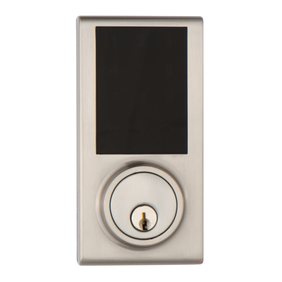
TOUCHPAD
ELECTRONIC DEADBOLT LOCK
1
2
3
4
5
6
7
8
9
0
USER MANUAL
Attention : Please do not use the "electronic" screwdriver for installation.
Advertisement
Table of Contents

Summarization of Contents
Limited Warranty Statements
Warranty Details
Manufacturer warrants the product for 12 months from the original purchase date.
Warranty Exclusions
Covers manufacturing defects, excludes misuse, abuse, or acts of God.
Limited Liability Clause
Manufacturer not liable for incidental or consequential losses.
Service Reminder
Requires warranty card and defective parts for service.
Hardware Screws Contents
Machine Screws
Details of machine screws included in the package.
Wood Screws
Details of wood screws included in the package.
Deadbolt Chassis Screws
Details of deadbolt chassis screws included.
Latch Backset Adjustment
Backset Adjustment Remarks
Notes on slight differences between two backsets.
Assembly Instructions
1. Backset Determination
Defines backset and compatibility for the adjustable latch.
2. Change Latch Face
Steps to change the latch faceplate for different mounting methods.
Drive-in Installation
Instructions for installing the drive-in latch.
3. Latch Backset Adjustment
Adjusting the latch for 2 3/8" (60 mm) or 2 3/4" (70 mm) backset.
5. Drill Holes
Drilling holes on the door for the lockset and latch.
8. Install Latch
Securing the latch assembly into the door using wood screws.
Install Drive-in Latch
Driving the latch into the door edge hole.
10.1 Drill Hole on Door Frame
Drilling a hole on the door frame for the strike plate.
11. Install Strike on Door Frame
Installing the strike plate into the door frame.
13. Install Touchpad Assembly
Installing the exterior cylinder and touchpad assembly.
15. Install Inside Mounting Plate
Attaching the interior mounting plate with screws.
16. Identify Door Handing
Determining if the door is left-handed or right-handed.
17. Adjust Thumb Turn Piece
Adjusting the thumb turn piece based on door handing.
19. Install Receiver Module
Connecting the IC wire and attaching the receiver module.
20. Insert Batteries
Installing batteries into the receiver module and replacing the cover.
Operational Interface
Programming Button
The button used for setting functions on the lock.
Lock Button
The button used for locking and unlocking the deadbolt.
Cylinder
The external cylinder for operating the lock with a key.
Battery Lid
The cover that slides to access and change batteries.
Battery Holder
The compartment designed to hold AA batteries.
R Button (Reset)
Button to restore the lock to original factory settings.
Turn-piece
The internal mechanism for locking/unlocking from inside.
Operating Instructions
Operation Indicator Sounds and Lights
Explains the meaning of different sounds and light signals from the lock.
1. Door Handling Identification Process
Process for the lock to automatically identify door handing.
2. Change Programming Code
Steps to change the lock's programming code.
3. Add New User Code
Procedure for adding new user access codes to the lock.
5. Delete All User Codes at Once
Method to remove all previously stored user codes.
6. Toggle Auto-Lock On/Off
Activates or deactivates the automatic locking feature.
7. Set Auto-Lock Time Delay
Configures the time delay before the auto-lock engages.
9. Create a One-Time User Code
Generates a user code that can only be used once.
10. Restore Default Settings
Resets the lock to its original factory settings.
Care and Maintenance
Cleaning Instructions
Guidance on cleaning the lock body without causing damage.
Warranty Information
Exclusions and Liability
Details warranty limitations, exclusions, and liability.
Z-Wave Connectivity
Adding Lock from Z-Wave Gateway
Steps to integrate the lock with a Z-Wave gateway.
Removing Lock from Z-Wave Gateway
Steps to disconnect the lock from a Z-Wave gateway.
Resetting Lock to Factory Defaults
Process to reset the lock to its original factory settings.
Z-Wave Device Specific Key (DSK)
The unique key for Z-Wave device identification.
Associations Groups
Group 1 Lifeline Commands
Describes commands sent to the Lifeline group for notifications.
FCC Compliance
FCC Part 15 Rules
Statement on compliance with FCC Part 15 regulations.
Regulatory Compliance
Compliance with Regulatory Bodies
Lists regulatory bodies the product complies with.
Important Safety Notice
Unauthorized Modifications Warning
Warning against modifications that could void user authority.


Need help?
Do you have a question about the KP300 and is the answer not in the manual?
Questions and answers