Advertisement
Limited Warranty Statements
1. Warranty
The manufacturer warrants the Product to be free
from defects in material and workmanship for a period of 12 months
from the original date of purchase.
If you discover a defect in the Product covered by this warranty, we will repair or
replace the item at our option using new or refurbished components.
2. Exclusions
This warranty covers defects in manufacturing discovered while using the
Products as recommended by The manufacturer rather than occurred by the act
of God, and damages caused by misuse, abuse, and unauthorized modification.
3. Limited of Liability
The manufacturer will not be held liable for incidental or consequential losses or
damages to any act of God.
4. Reminder
Service requirement shall subject to the presentation of this warranty card
and defective parts to the manufacturer.
The warranty card will not be reissued if lost.
Product :
Purchase Date :
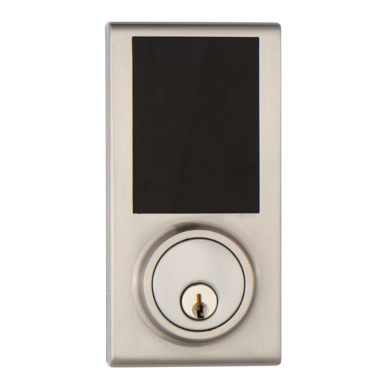
TOUCHPAD
ELECTRONIC DEADBOLT LOCK
1
2
3
4
5
6
7
8
9
0
USER MANUAL
Attention : Please do not use the "electronic" screwdriver for installation.
Advertisement
Table of Contents


Need help?
Do you have a question about the ZW300 and is the answer not in the manual?
Questions and answers
Where is the qr cide