Table of Contents
Advertisement
Quick Links
Advertisement
Table of Contents

Related Manuals for HB-THERM THERMO-5 HB-140Z1


Summary of Contents for HB-THERM THERMO-5 HB-140Z1
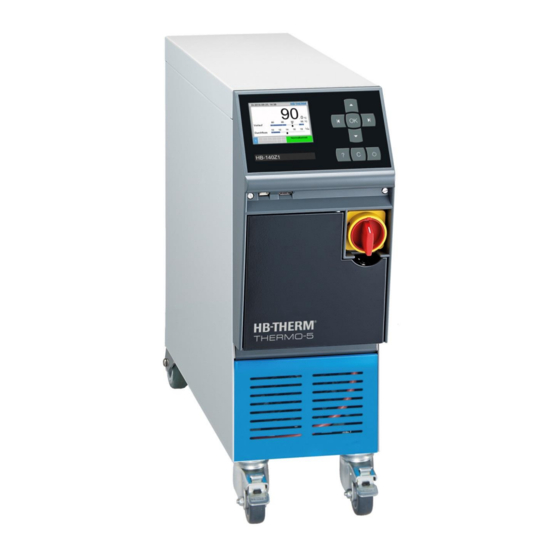
- Page 1 Instruction Manual HB-100/140/160Z1 Temperature Control Unit...
- Page 2 Contents 2017-12 O8285-EN Instr ucti on Manual HB-100/140/160Z1 Temperatur e C ontrol U nit HB-THERM AG Spinnereistrasse 10 (WU 3) Postfach 9006 St. Gallen Switzerland www.hb-therm.ch (Typenschild) E-Mail info@hb-therm.ch Phone +41 71 243 6-530 +41 71 243 6-418 Translation of original instruction...
-
Page 3: Table Of Contents
HB-100/140/160Z1 Temperature Control Unit Contents Index ....................7 General ..................9 Information about this manual ........9 Explanation of symbols ..........10 Limitation of liability ........... 11 Copyright ..............11 Warranty terms ............12 Customer Service ............12 Safety ..................13 Intended Use ............. - Page 4 HB-100/140/160Z1 Temperature Control Unit Contents Storage ..............38 Installation and initial commissioning ....... 39 Safety ................ 39 Requirements for the installation location ....40 Installation work ............41 6.3.1 Lock castors ..........41 6.3.2 Water treatment ......... 41 6.3.3 Set the separate connection for system water ............
- Page 5 HB-100/140/160Z1 Temperature Control Unit Contents 8.9.5 Cyclical change-out of the system water ... 87 8.10 Process monitoring ............ 88 8.10.1 Limit value monitoring ........ 88 8.10.2 Monitor pump wear ........90 8.10.3 Optimise controller ........91 8.11 Explorer window ............92 8.12 Save/Load ..............
- Page 6 HB-100/140/160Z1 Temperature Control Unit Contents Appendix Special execution Spare parts list O8285-EN 2017-12...
-
Page 7: Index
HB-100/140/160Z1 Temperature Control Unit Index Index overview ............116 Functional principle ..........29 Access code ............81 Access rights ............80 Heat transfer medium ........29 Additional equipment .......... 31 Hydraulic connections ........30 Hydraulic scheme ..........123 Basic display ............51 Hydraulic specialist .......... - Page 8 HB-100/140/160Z1 Temperature Control Unit Index Sound pressure level ......... 24 Spare parts ............120 Nameplate ............27 Special Design ............. 9 Nominal value 2 ..........71 Status display ............. 52 Normal operation ..........67 Stickers .............. 21 Storage .............. 38 Opening the unit ..........
-
Page 9: General
HB-100/140/160Z1 Temperature Control Unit General 1 General 1.1 Information about this manual This manual enables the safe and efficient handling of the unit. The manual is a component part of the unit and must always be kept close to the unit readily accessible for personnel. Before starting any work, the personnel must have carefully read through and understood this manual. -
Page 10: Explanation Of Symbols
HB-100/140/160Z1 Temperature Control Unit General 1.2 Explanation of symbols Warnings Warnings are identified by symbols. These warnings are introduced by signal words, which express the severity of a danger. Adhere to these warnings and act cautiously in order to avoid accidents, personal injuries and damage to property. -
Page 11: Limitation Of Liability
HB-100/140/160Z1 Temperature Control Unit General 1.3 Limitation of liability All information and notes in this Manual were compiled under due consideration of valid standards and regulations, the present status of technology and our years of knowledge and experience. The manufacturer can not be made liable for damage resulting from: ... -
Page 12: Warranty Terms
1.5 Warranty terms The warranty terms are provided in the manufacturer's terms and conditions. 1.6 Customer Service For technical information, please contact the HB-Therm representatives or our customer service department www.hb-therm.ch. Furthermore, our employees are always interested in new infor- mation and experiences resulting from the application that could be valuable for the improvement of our products. -
Page 13: Safety
HB-100/140/160Z1 Temperature Control Unit Safety 2 Safety This paragraph provides an overview of all important safety aspects for optimal protection of personnel as well as safe and trouble-free operation. Disregarding this Manual and safety regulations specified therein may result in considerable danger. 2.1 Intended Use The unit is designed and constructed exclusively for the intended use described here. -
Page 14: Customer's Responsibility
HB-100/140/160Z1 Temperature Control Unit Safety 2.2 Customer’s responsibility The device is implemented commercially. Thus the owner of the device is subject to legal industrial safety obligations. In addition to the safety instructions in this Manual, the safety, accident prevention guidelines and environmental protection regulations, applicable at the site of implementation must be complied with. -
Page 15: Personnel Requirements
HB-100/140/160Z1 Temperature Control Unit Safety 2.3 Personnel requirements 2.3.1 Qualifications WARNING! Danger of injury if insufficiently qualified! Improper operation can lead to serious personal injuries or property damage. Therefore: – Have all activities performed only by qualified personnel. The following qualifications are specified for different areas of activity listed in the Manual. -
Page 16: Unauthorized Persons
HB-100/140/160Z1 Temperature Control Unit Safety 2.3.2 Unauthorized persons WARNING! Danger for unauthorized persons! Unauthorized persons not meeting the requirements outlined here are not aware of the dangers in the work area. Therefore: – Keep unauthorized persons away from the work area. -
Page 17: Personal Protective Equipment
HB-100/140/160Z1 Temperature Control Unit Safety 2.4 Personal protective equipment When working, it may be necessary to wear personal protective equipment in order to minimise dangers to health. During work, always wear the protective equipment necessary for the particular work. ... -
Page 18: Specific Dangers
HB-100/140/160Z1 Temperature Control Unit Safety 2.5 Specific dangers The following section lists the residual risks that have been determined by the risk assessment. Heed the safety instructions listed here, and the warnings in subsequent chapters of this Manual, to reduce health hazards and to avoid dangerous situations. - Page 19 HB-100/140/160Z1 Temperature Control Unit Safety Hot surfaces CAUTION! Danger of burning on hot surfaces! Contact with hot components can cause severe burns. Therefore: – Always wear protective clothes and protective gloves when working on hot components. – Before starting work make sure that all components have cooled down to ambient temperature.
-
Page 20: Safety Devices
HB-100/140/160Z1 Temperature Control Unit Safety 2.6 Safety devices WARNING! Malfunctioning safety devices may pose a fatal risk! Safety devices must be intact in order to guarantee safety. Therefore: – Never disable safety devices. – Take care to ensure that safety devices such as main switch are always accessible. -
Page 21: Stickers And Decals
HB-100/140/160Z1 Temperature Control Unit Safety 2.7 Stickers and decals The following symbols and information decals can be found in the danger zone. They refer to the immediate vicinity around their location. WARNING! Danger of injury because of illegible symbols! Over the course of time stickers and decals may become dirty or illegible for any other reason. -
Page 22: Ce Declaration Of Conformity For Machinery
HB-100/140/160Z1 Temperature Control Unit Safety 2.8 CE Declaration of Conformity for Machinery (CE-Directive 2006/42/EG, Annex II 1. A.) Product Temperature Control Unit HB-Therm Thermo -5 Unit types HB-100Z1 HB-140Z1 HB-160Z1 HB-THERM AG Manufacturer Address Spinnereistrasse 10 (WU 3) Postfach 9006 St. Gallen Switzerland www.hb-therm.ch... -
Page 23: Technical Data
HB-100/140/160Z1 Temperature Control Unit Technical data 3 Technical data 3.1 General Information Fig. 2: Dimensions Value Unit Max. weight HB-100Z1 HB-140Z1 HB-160Z1 Value Unit Temperature measurement Measuring range 0–400 °C Dissolution °C Control accuracy ±0,1 Tolerance ±0,8 Value Unit Flow measurement Measuring range 0,4–40 L/min... -
Page 24: Emissions
HB-100/140/160Z1 Temperature Control Unit Technical data 3.2 Emissions Value Unit Continuous sound pressure level <67 dB(A) Surface temperature (rear of unit) >55 °C 3.3 Operating conditions Value Unit Environment Temperature range 5–40 °C Relative humidity* 35–85 % RH * non-condensing O8285-EN 2017-12... -
Page 25: Connection Values
HB-100/140/160Z1 Temperature Control Unit Technical data 3.4 Connection values Electrical connection see nameplate on unit or on page 2 Value Unit Connection main and return line Thread G¾ Resistance HB-100Z1 20, 120 bar, °C Resistance HB-140Z1 20, 160 bar, °C Resistance HB-160Z1 20, 180 bar, °C... -
Page 26: Operating Fluids
Manganese Mn <0.1 mg/L NOTICE! For further information, you can go to www.hb-therm.ch to download "Checklist for water treatmentfor temperature control units" (DF8003-X, X=language). Water treatment If the guideline values cannot be observed, a professional water treatment is necessary ( page 41). -
Page 27: Nameplate
HB-100/140/160Z1 Temperature Control Unit Technical data 3.6 Nameplate The nameplate is located on the rear panel of the unit, on the inside of the service flap and on page 2 o these operating instructions. The following information can be taken from the nameplate: ... -
Page 28: Structure And Function
HB-100/140/160Z1 Temperature Control Unit Structure and function 4 Structure and function 4.1 Overview Fig. 3: Overview Heat transfer module Cooler Operation and display Filling pump Pump Cooling water module 4.2 Brief description The temperature control unit uses a heater and a cooler to bring the heat transfer medium water to the desired temperature and keeps this constant. -
Page 29: Functional Principle
HB-100/140/160Z1 Temperature Control Unit Structure and function 4.3 Functional principle The temperature control unit is a self-venting system. It comprises a pump, a heating element and a cooling element and serves as a pressure vessel for the heat transfer medium. A temperature sensor measures the temperature of the heat transfer medium in the temperature control unit and forwards it in the form of an electrical signal to the controller input. -
Page 30: Connections
HB-100/140/160Z1 Temperature Control Unit Structure and function 4.5 Connections The connections and important components on the rear of the unit are marked as follows: Main line Return line Cooling water inlet Cooling water outlet Drain Pressure indicator Cooling water filter System water inlet * System water outlet * AIR IN... -
Page 31: Additional Equipment
HB-100/140/160Z1 Temperature Control Unit Structure and function 4.6 Additional equipment The following additional equipment can be installed in addition to the basic equipment for the unit ( nameplate): Additional equipment Description Leak stopper With automatic depression optimisation (up to 70 °C) Mould evacuation with compressed air Alternative to the standard integrated Mould evacuation by pump inversion Connection for alarm and external... -
Page 32: Operation Modes
HB-100/140/160Z1 Temperature Control Unit Structure and function 4.7 Operation modes 4.7.1 Main operating modes NOTE! After switching the unit on, the last main operating mode selected is again active, if necessary after expiry of a delay time Normal operation During normal operation, the temperature controlled heat transfer medium is pressed through the consumers by means of a pump. -
Page 33: Work And Danger Zones
HB-100/140/160Z1 Temperature Control Unit Structure and function 4.8 Work and danger zones Working areas The primary working area is located at the front of the unit on the keyboard. The secondary working area is located at the rear of the unit. Danger areas ... -
Page 34: Transport, Packing And Storage
HB-100/140/160Z1 Temperature Control Unit Transport, packing and storage 5 Transport, packing and storage 5.1 Safety notes for transport Improper transport ATTENTION! Damage due to improper transport! Improper transport can result in considerable material damage. Therefore: – Unit must be completely emptied (cooling and system circuit) –... - Page 35 HB-100/140/160Z1 Temperature Control Unit Transport, packing and storage Transport with a crane The unit can be equipped with lifting brackets (special design). Transport with a crane can be carried out under the following conditions: Crane and lifting gear must be designed for the weight of the unit.
-
Page 36: Transport Inspection
HB-100/140/160Z1 Temperature Control Unit Transport, packing and storage 5.3 Transport inspection Check the delivery immediately on receipt for completeness and transport damage. If externally detectable transport damage is found, proceed as follows: Do not accept the delivery, or only with reservation. ... -
Page 37: Symbols On The Packing
HB-100/140/160Z1 Temperature Control Unit Transport, packing and storage Handling packing materials If there is no returns agreement for the packing, separate materials according to type and size and direct to further use or recycling. ATTENTION! Environmental damage caused by incorrect waste disposal! Packing materials are valuable raw materials and can continue to be used in many cases or sensibly... -
Page 38: Storage
HB-100/140/160Z1 Temperature Control Unit Transport, packing and storage 5.6 Storage Storing the packages Store the packages under the following conditions: Temperature control unit completely emptied. Do not store out of doors. Store dry and dust-free. Do not expose to aggressive media. ... -
Page 39: Installation And Initial Commissioning
HB-100/140/160Z1 Temperature Control Unit Installation and initial commissioning 6 Installation and initial commissioning 6.1 Safety Personnel The installation and commissioning must only be carried out by qualified personnel. Work on the electrical system must only be carried out by certified electricians. -
Page 40: Requirements For The Installation Location
HB-100/140/160Z1 Temperature Control Unit Installation and initial commissioning 6.2 Requirements for the installation location WARNING! Improper installation can cause risk of injury and fire! Improper installation can lead to severe personal injury or material damage. Therefore: – Observe and comply with the requirements at the installation site Install the temperature control unit under the following conditions: ... -
Page 41: Installation Work
HB-100/140/160Z1 Temperature Control Unit Installation and initial commissioning 6.3 Installation work 6.3.1 Lock castors The castors must be locked in order to secure the unit from rolling away unintentionally. Place the unit in the appropriate location. Press the two brake arms on the castors downwards. Fig. -
Page 42: Set The Separate Connection For System Water
HB-100/140/160Z1 Temperature Control Unit Installation and initial commissioning 6.3.3 Set the separate connection for system water The common connection for cooling and system water can be changed over to separate connections. Necessary equipment Torx screwdriver Slotted screwdriver Separate connection cooling and Proceed as follows in order to change to separate connection for system water inlet cooling and system water inlet:... -
Page 43: Setting Up System Connections
HB-100/140/160Z1 Temperature Control Unit Installation and initial commissioning 6.3.4 Setting up system connections WARNING! Danger from hydraulic energy! When using unsuitable pressure lines and connectors, the danger exists that liquids under high pressure can escape and cause severe or fatal injuries. Therefore: –... - Page 44 HB-100/140/160Z1 Temperature Control Unit Installation and initial commissioning Connect cooling water inlet and NOTE! outlet In order to optimally utilize the cooling capacity of the temperature control unit, keep the cooling water outlet as short and free of back-pressure as possible.
-
Page 45: Connect Data Interfaces
ZC / ZP at Thermo-5 resp. Panel-5. Plug the control cable into socket HB IN. Attach the other side of the control cable to the HB-Therm Thermo-5, Flow-5 or Vario-5 through the HB IN plug. Fig. 11: Interfaces individual unit Attach additional HB-Therm products through the socket HB OUT. - Page 46 HB-100/140/160Z1 Temperature Control Unit Installation and initial commissioning Communication examples Data interface (additional In order to control the unit via an external controller, a control cable equipment ZD, ZC, ZP, ZO) can be connected to the unit: Pull the control cable between the front and the service cover. Plug the control cable into socket ZD, ZC, ZP or ZO.
-
Page 47: Connect External Sensor
HB-100/140/160Z1 Temperature Control Unit Installation and initial commissioning External control In order to control the unit via potential-free external contacts, an (additional equipment ZB) external control cable can be connected to the unit: Loop the external control cable between the front and the service flap. -
Page 48: Control
HB-100/140/160Z1 Temperature Control Unit Control 7 Control 7.1 Keyboard Fig. 18: Keyboard and display 7.1.1 Key functions on an individual unit Key function in basic Key function within menu Key function with active parameter display adjustment In menu Nominal values jump Navigate upwards. -
Page 49: Key Functions And Operation On An Individual Unit
HB-100/140/160Z1 Temperature Control Unit Control 7.1.2 Key functions and operation on an individual unit Key function in basic Key function within menu Key function with active display parameter adjustment In menu Nominal values Navigate upwards. Increase values. jump to Nominal value 1 (adjustment mode). -
Page 50: Key Functions On Unit Operated As Module
HB-100/140/160Z1 Temperature Control Unit Control 7.1.3 Key functions on unit operated as module Key function in basic Key function within menu Key function with active display parameter adjustment no function Navigate upwards. Increase value. no function no function no function Display main menu. -
Page 51: Basic Display
HB-100/140/160Z1 Temperature Control Unit Control 7.1.4 Basic display Fig. 19: Basic display table Fig. 20: Basic display graph Fig. 21: Basic display text Fig. 22: Basic display Unit operated as module Pos. Designation Display Menu bar Date and time Temperature scale Scale for current measuring position (main line, return line or external) Text actual value... - Page 52 HB-100/140/160Z1 Temperature Control Unit Control Status indication individual unit The condition display lights in a different colour depending on the operating condition. The following conditions are defined: Display Description green trouble-free green flashing start-up phase, limiting values not set yellow warning fault Status display operate unit as...
-
Page 53: Operating Structure
HB-100/140/160Z1 Temperature Control Unit Control 7.2 Operating structure Navigate through the menu structure as follows: Use the key to display step-by-step the next lowest hierarchy level starting from the basic display. Use the key to display step-by-step the next highest hierarchy level up to the basic display. -
Page 54: Menu Structure
HB-100/140/160Z1 Temperature Control Unit Control 7.3 Menu structure NOTE! Depending on the software version used, the menu structure and the parameter values can deviate from the following table. Display Nominal values Nominal value 1 40,0 °C Nominal value 2 °C Nominal speed 100,0 Nominal flow rate... - Page 55 HB-100/140/160Z1 Temperature Control Unit Control External °C Deviation actual/nominal Difference return/main line Regulation ratio Flow rate L/min Process power act. Power saving. Pump Energy saving pump Possibili. Power sav. Pump 4S, 4M Possibili. Energy sav. Pump 4S, 4M Nominal temperature difference Nominal flow rate L/min Nominal pressure difference...
- Page 56 HB-100/140/160Z1 Temperature Control Unit Control Output pump Production detection inactive Selection Nominal value (current) Main line Return line External Deviation actual/nominal Difference return/main line Regulation ratio Flow rate Process power act. Power saving. Pump Energy saving pump Possibili. Power sav. Pump 4S, 4M Possibili.
- Page 57 HB-100/140/160Z1 Temperature Control Unit Control Position cooling valve 2 >100 °C Level tank 200/250T Temperature cooler >100 °C Temperature tank 200/250T Temperature frequency Converter Temperature compensation 1 Power pump Nom. value pumps (current) Output pump Production detection Module Module External flow meter External flow meter Miscellaneous External flow meter...
- Page 58 HB-100/140/160Z1 Temperature Control Unit Control Tool 1-10 Tool no. Nominal value 1 °C Difference return/main line Difference main line/external Upper dev. nominal/actual Lower dev. nominal/actual Flow rate internal max. L/min Flow rate internal min. L/min Load tool data Save tool data export tool data import tool data Level...
- Page 59 HB-100/140/160Z1 Temperature Control Unit Control Switch clock Time HH:MM Date Status inactive Mo-Fr Switch mode Switch time 06:00 HH:MM Ramp programme Criterion ramp programme nominal End ramp programme Status inactive Temperature °C Time 00:00 HH:MM Controller Measuring point internal Main line Auto-Tuning Operating mode autom.
- Page 60 HB-100/140/160Z1 Temperature Control Unit Control Pressure scale Recording USB Serial recording cycle Activate all values Deactivate all values Nominal value (current) Main line Return line External Deviation actual/nominal Difference return/main line Regulation ratio Flow rate Process power act. Power saving. Pump Energy saving pump Possibili.
- Page 61 HB-100/140/160Z1 Temperature Control Unit Control Maintenance cooler Difference main line/external Return line external 1..8 Diff. return/main line ext. 1..8 Flow rate external 1..8 Process power ext. 1..8 Position cooling valve 1 Position cooling valve 2 >100 °C Level tank 200/250T Temperature cooler >100 °C Temperature tank...
- Page 62 HB-100/140/160Z1 Temperature Control Unit Control Rinse interval Rinse time Limitation filling time Temperature limiting °C Safety cut-off temperature °C Max. temperature air relief °C Function nominal value 3 Ext. contact read at mains ON Mould evac. with compr. air Drain DFM recognition integrated Profile...
-
Page 63: Operation
HB-100/140/160Z1 Temperature Control Unit Operation 8 Operation 8.1 Mains ON Switch on the temperature control unit as follows: Turn the main switch to position "I". Unit initialisation runs. The indication "Ready-to-operate" appears on the display. Fig. 24: Main switch O8285-EN 2017-12... -
Page 64: Registering New Modular Units
HB-100/140/160Z1 Temperature Control Unit Operation 8.2 Registering new modular units Initialisation window If a new modular unit is detected, the initialisation window appears at the operating module or individual unit. Pos. No. Display GIF-ID Status of modular unit Address of modular unit Fig. -
Page 65: Special Features For Operation Of Modular Units
HB-100/140/160Z1 Temperature Control Unit Operation 8.3 Special features for operation of modular units Parameter types: For modular units, the distinction is made between 2 types of parameter: Module independant (value adjustment only possible for "1..99") Module dependent (value adjustment possible per module) NOTE! The parameters that can be set module indepedently or module dependently can be taken... -
Page 66: Operate Singular Unit As Modular Unit
HB-100/140/160Z1 Temperature Control Unit Operation 8.4 Operate singular unit as modular unit An singual unit can be operated as a modular unit. The operation takes place through the higher-level command Thermo-5 or Panel-5. Requirement Additional equipment ZC only one module logged on. ... -
Page 67: Switching On
HB-100/140/160Z1 Temperature Control Unit Operation 8.5 Switching on 8.5.1 Normal operation Switch on individual unit Switch on normal operation as follows: Press the key. The unit starts in the defined operating mode. If necessary, the unit is automatically filled and vented. Ensure that the functions Mould evacuation, Leak stopper, 2nd nominal value... -
Page 68: Leak Stopper
HB-100/140/160Z1 Temperature Control Unit Operation 8.5.2 Leak stopper (additional equipment ZL) NOTE! The leak stopper can not be switched on or will be interrupted when main or return line exceed an operating temperature of 70 °C. Switch on the leak stopper as follows: Display menu page Functions. -
Page 69: External Sensor
HB-100/140/160Z1 Temperature Control Unit Operation 8.5.3 External sensor Function In order to precisely control the temperature of a consumer, an (additional equipment ZE) external temperature sensor can be connected to the unit: Pre-selection of external sensor NOTE! type The sensor type Pt 100 is automatically recognised and adjusted. - Page 70 HB-100/140/160Z1 Temperature Control Unit Operation Production detection For applications with the sensor close to the cavity, physically caused temperature deviations due to production interruptions can occur. When production detection is switched on, switchover is made to main line control on production interruption. Temperature deviations are avoided.
-
Page 71: Mode 2Nd Nominal Value
HB-100/140/160Z1 Temperature Control Unit Operation 8.5.4 Mode 2nd nominal value NOTE! The function 2nd nominal value is only displayed when the parameter Nominal value 2 on menu page Nominal values is set to a value greater than "0.0". Switch on the mode 2nd nominal value as follows: Display menu page Functions. -
Page 72: Remote Mode
HB-100/140/160Z1 Temperature Control Unit Operation 8.5.5 Remote mode In remote control mode the temperature control unit is controlled by external signals. Two types of external signal are supported. NOTE! For the pin assignment of the various interface cables page 130. External control connection By means of a potential-free external contact, the temperature (additional equipment ZB) - Page 73 HB-100/140/160Z1 Temperature Control Unit Operation Remote mode settings Operation and monitoring of the temperature control unit can take (additional equipment ZD, ZC, place via the serial interface. ZP, ZO) The following settings must be made in order to communicate with an external controller: Display the menu page Setting \ Remote operation...
- Page 74 HB-100/140/160Z1 Temperature Control Unit Operation Protocol Used for Internal communication (only use when setting is operate unit as module) Recording text Arburg, Billion, Bühler, Dr. Boy, Ferromatik Milacron, KraussMaffei, Negri Bossi, Sumitomo Demag, Wittmann Battenfeld, Zhafir Sumitomo Demag (CAN) Engel, Haitian Stork EUROMAP 66 (CANopen) MODBUS (RTU-Mode)
-
Page 75: Switching Off
HB-100/140/160Z1 Temperature Control Unit Operation 8.6 Switching off After use, switch the temperature control unit off as follows: Press the key. The temperature control unit cools until the main and return line temperature is lower than the set safety cut-off temperature. -
Page 76: Cooling Down And Switching Off
HB-100/140/160Z1 Temperature Control Unit Operation 8.6.1 Cooling down and switching off If necessary, before switching on the cooling, set the cooling temperature and the cooling duration: Display the menu page Setting \ Miscellaneous. Set parameter Cooling temperature to the desired value. Set parameter Wait after cooling to the desired value. -
Page 77: Mould Evacuation
HB-100/140/160Z1 Temperature Control Unit Operation 8.6.2 Mould evacuation If necessary, before switching on mould evacuation, set the desired mould evacuation duration: Display the menu page Setting \ Miscellaneous. Set parameter Time mould evacuation to the desired value. Fig. 46: Setting mould evacuation time Switch on mould evacuation as follows: Display menu page Functions. -
Page 78: Mould Evacuation With Compressed Air
HB-100/140/160Z1 Temperature Control Unit Operation 8.6.3 Mould evacuation with compressed air Additional equipment ZG With this function, all connected consumers and supply hoses are emptied with compressed air and depressurised. Switch on mould evacuation ( page 77) Emptying into cooling or system Set the outlet for emptying as follows: water outlet Display the menu page... -
Page 79: Emergency Stop
HB-100/140/160Z1 Temperature Control Unit Operation 8.7 Emergency stop In dangerous situations, the unit must be stopped as quickly as possible and the power supply switched off. Emergency stop Proceed as follows in a hazardous situation: Turn the main switch to "0". Disconnect from the mains or disconnect all phases of the external power supply and secure them against being switched on again. -
Page 80: Define Access Rights
HB-100/140/160Z1 Temperature Control Unit Operation 8.8 Define access rights 8.8.1 Set user profile Function In order to avoid operating error and to improve clarity, menus, functions and parameters are suppressed corresponding to the set user profile. Differentiating user profiles A differentiation is made between the following user profiles. User profile Code User/Characteristic Standard... -
Page 81: Change Access Code
When the unit is delivered, the access code is 1234. NOTE! For protection against misuse of the unit, change the access code immediately after commissioning. If the current code is lost, please contact the nearest HB-THERM representative. Change access code To change the access code: Display menu page Profile... -
Page 82: Settings
HB-100/140/160Z1 Temperature Control Unit Operation 8.9 Settings 8.9.1 Setting time zone, date and time Set time zone By default, date and time of the unit are set to Central European Time (CET) at delivery. To accommodate for different time zones, date and time must be set manually before commissioning. -
Page 83: Define Internal Measuring Points
HB-100/140/160Z1 Temperature Control Unit Operation 8.9.2 Define internal measuring points Function Main and return line sensors are integrated in the temperature control unit as standard. One of these two measuring points is fed to the internal controller as the actual value. Pre-selection of internal Proceed as follows to switch over the internal temperature sensor: temperature sensor... -
Page 84: Set Switch Clock
HB-100/140/160Z1 Temperature Control Unit Operation 8.9.3 Set switch clock Function With the switch clock, the temperature control unit can be switched on and off at pre-programmed times and days. Turn switch clock on or off. Proceed as follows in order to turn the switch clock on or off: Display menu page Functions. -
Page 85: Set Ramp Programme
HB-100/140/160Z1 Temperature Control Unit Operation 8.9.4 Set ramp programme Function With the ramp programme, a defined temperature profile comprising up to ten steps can be run. When the ramp programme runs, the nominal value continuously changes corresponding to the temperatures and times defined per programme step. Set ramp programme Proceed as follows in order to set the ramp programme individually: Display the menu page... - Page 86 HB-100/140/160Z1 Temperature Control Unit Operation Interrupt ramp programme Proceed as follows in order to interrupt the running ramp programme: Display menu page Functions. Select the function Ramp BREAK and activate or deactivate with the key. The activated function is indicated with the symbol.
-
Page 87: Cyclical Change-Out Of The System Water
HB-100/140/160Z1 Temperature Control Unit Operation 8.9.5 Cyclical change-out of the system water During operation, water fed in through the cold-water or system- water feed stays in the heat-transfer circuit. You are therefore advised to switch on the cyclical change-out of the system water if you are using a Treat 5 water-treatment device or a water- treatment system. -
Page 88: Process Monitoring
HB-100/140/160Z1 Temperature Control Unit Operation 8.10 Process monitoring 8.10.1 Limit value monitoring Function After each unit start-up, the limit values for process monitoring are automatically determined and set in the standard settings according to the set monitoring level. NOTICE! If the limit values have not been set, the operating mode indicator flashes green. - Page 89 HB-100/140/160Z1 Temperature Control Unit Operation Set monitoring level The tolerance range is determined with the parameter Monitoring level and can be adapted as follows: Display menu page Monitoring. Set parameter Monitoring level to "fine", "middle" or "rough". Fig. 62: Monitoring level The limit values for temperature, flow rate and pressure are calculated according to the following table: Designation...
-
Page 90: Monitor Pump Wear
HB-100/140/160Z1 Temperature Control Unit Operation 8.10.2 Monitor pump wear Function With pump wear monitoring, the condition of the pump is constantly (additional equipment ZU) monitored. On falling below the defined value for parameter Pump condition min., the system issues a warning message and this is indicated on the basic display with the symbol. -
Page 91: Optimise Controller
If the cooling or heating capacity is insufficinet to carry out controller optimisation, then this will be aborted after 30 minutes. NOTE! If, despite controller optimisation, the regulation quality is inadequate, please contact the nearest HB-THERM representative. ( www-hb-therm.ch) O8285-EN 2017-12... -
Page 92: Explorer Window
HB-100/140/160Z1 Temperature Control Unit Operation 8.11 Explorer window The Explorer window displays the directories and files on the inserted USB data carrier. Directories with are opened with the key. Directories with are closed with the key. NOTE! Depending on the number of files and directories on the USB data carrier, it can take several minutes before the directory structure is displayed. -
Page 93: Save/Load
In case of failure, the service information can be stored on an USB device for fault diagnosis by a representative of HB-Therm. WARNING! Damage due to wrong settings! Loading wrong parameter or configuration data can lead to malfunction or total breakdown. - Page 94 HB-100/140/160Z1 Temperature Control Unit Operation Loading data Proceed as follows in order to load data to the unit from a USB data carrier: Display menu page Save/Load. Connect USB data carrier to front connector. Select the data to be loaded and confirm with the key.
-
Page 95: Tool Data
HB-100/140/160Z1 Temperature Control Unit Operation 8.12.1 Tool data Function A maximum of 10 tool data sets with defined tool-specific parameters can be stored in the unit. Tool-specific parameters A tool data set comprises the following parameters: Parameter Comment Tool No. Tool name, max. - Page 96 HB-100/140/160Z1 Temperature Control Unit Operation Export tool data Proceed as follows in order to export the selected tool data set to a USB data carrier: Connect USB data carrier to front connector. Display menu page Monitoring \ Tool data \ Tool 1..10.
-
Page 97: Recording Actual Data
HB-100/140/160Z1 Temperature Control Unit Operation 8.12.2 Recording actual data Function When the Record USB function is activated, the values selected in Setting \ Recording USB are written to the USB data carrier.- A new recording file is created each day. If saving to the USB data carrier is not possible, a corresponding warning is displayed.- Start recording Proceed as follows to start recording actual data to a USB data... - Page 98 Device type NOTICE! The GIF-ID can be seen under Display \ Module. Visualize the data recorded To visualize and prepare the actual data recorded, the VIP (Visualisation programme – Recording of actual values) software can be downloaded from www.hb-therm.ch. O8285-EN 2017-12...
-
Page 99: Maintenance
HB-100/140/160Z1 Temperature Control Unit Maintenance 9 Maintenance 9.1 Safety Personnel Maintenance tasks described here can be performed by the operator, unless otherwise indicated. Some maintenance tasks must only be carried out by qualified personnel or by the manufacturer exclusively. If this is required, it is pointed out separately in the description of the respective faults. -
Page 100: Open The Unit
HB-100/140/160Z1 Temperature Control Unit Maintenance 9.2 Open the unit The unit has to be opened for specific maintenance work. Only to be carried out by a specialist or instructed person. Necessary tools (depending on unit status): Torx screwdriver. ... - Page 101 HB-100/140/160Z1 Temperature Control Unit Maintenance Use a screwdriver to loosen and remove the screw in the cover plate. Fig. 73: Loosen screws Pull the cover plate approx. 1 cm to the rear and lift off upwards. Fig. 74: Remove cover plate Pull the side plate slightly upwards.
-
Page 102: Maintenance Schedule
For questions concerning maintenance work and intervals, please contact the HB-THERM representative ( www.hb-therm.ch). The pump, heating and cooler components are subject to the integrated maintenance interval. - Page 103 HB-100/140/160Z1 Temperature Control Unit Maintenance Interval Assembly / Component Maintenance work Carried out Every 1½ years Hydraulic hose lines Check for damage on outer sheath and in Hydraulic or ~6000 h (internal) the sealing area specialist Replace if necessary Hydraulic specialist Temperature limiter main Check fixing...
-
Page 104: Maintenance Tasks
HB-100/140/160Z1 Temperature Control Unit Maintenance 9.4 Maintenance tasks 9.4.1 Cleaning Clean the unit under the following conditions: Only clean the outer parts of the unit with a soft, moist cloth. Do not use any aggressive cleaning agents. O8285-EN 2017-12... -
Page 105: Pump
Necessary equipment Test control unit for quality control (condition of the pump), further information under www.hb-therm.ch. NOTICE! No test control unit is required if there is a built-in pump wear monitor (ZU). -
Page 106: Temperature Measurement
With a deviation of >3 °C, the temperature sensor in the unit must be checked. With larger linear errors, the individual temperature sensors can be calibrated on menu page Service \ Calibration \ Temperature. If you have any questions, please contact your nearest HB-THERM - representative ( www.hb-therm.ch). O8285-EN 2017-12... -
Page 107: Pressure Measurement
Necessary equipment no special equipment Optionally, test equipment can be used for the pressure measurement. Further information under www.hb-therm.ch Procedure Switch off the temperature control unit by means of mould evacuation. Uncouple consumers on main and return lines. Manometer pressure indicator must indicate 0 bar +0.3 bar. -
Page 108: Safety Valve
HB-100/140/160Z1 Temperature Control Unit Maintenance 9.4.5 Safety valve Check the function of the safety valve Only to be carried out by a specialist. Procedure Remote the unit covers. Switch on temperature control unit (normal operation). Set nominal value to 40 °C. Open the knurled nut on the safety valve until a little water escapes via the overflow. -
Page 109: Software Update
Necessary tools: USB data carrier with the current software The latest software can be acquired from the HB-THERM representative ( www.hb-therm.ch). NOTICE! Only USB data carriers in FAT32 format are supported. - Page 110 HB-100/140/160Z1 Temperature Control Unit Maintenance Run software update Switch on main switch. Connect USB data carrier (Fig. 77). Display menu page Profile. Set parameter User profile to "Enhanced". Display menu page Save/Load. Select function Start USB Software Update and confirm with key.
-
Page 111: Gain Access To Components
HB-100/140/160Z1 Temperature Control Unit Maintenance 9.4.7 Gain access to components To gain access to components and to replace these, if necessary, the unit must first be opened ( page 100). Heating Completely empty the temperature control unit. Remove the fixing screw (2) on the side of the heater support. Unplug the brass block (3) from the heater. - Page 112 HB-100/140/160Z1 Temperature Control Unit Maintenance Valves Completely empty the temperature control unit. Remove the fixing screws for the cover plate (1) on the lower rear panel and remove the cover plate Fig. 82: Valve cover Unit board Disconnect the mains plug from the mains supply. Loosen the screws in the front panel.
-
Page 113: Faults
In the case of faults, which can not be remedied by the following instructions, contact the HB-THERM representative ( www.hb-therm.ch). For error diagnoses, service information can be saved to a USB data carrier and sent to the HB-THERM representative ( page 93). 10.1 Safety ... - Page 114 HB-100/140/160Z1 Temperature Control Unit Faults Maintenance / repair work carried WARNING! out improperly Danger of injury due to maintenance / repair work carried out improperly! Improper maintenance / repair work can lead to severe personal injury or material damage. Therefore: –...
-
Page 115: Fault Indications
Acknowledge horn with the key. is displayed in the symbol field . Determine the cause of a fault. If required, contact the HB- THERM representative ( www.hb-therm.ch). Acknowledge alarm with the O8285-EN 2017-12... -
Page 116: Determine The Cause Of A Fault
HB-100/140/160Z1 Temperature Control Unit Faults 10.3 Determine the cause of a fault Cause of a fault Proceed as follows to identify the possible causes for a current fault indication: Press the key to display the online help for the pending fault indication. - Page 117 HB-100/140/160Z1 Temperature Control Unit Faults Fault Possible cause Rectification Rectified by Overtemperature circuit Cooling water connection not Make the cooling water Qualified made correctly connection properly personnel Cooling valve 1 or cooling Check cooling valve 1 or Qualified valve 2 defective cooling valve 2, replace if personnel necessary...
-
Page 118: Startup After Eliminating Fault
HB-100/140/160Z1 Temperature Control Unit Faults Fault Possible cause Rectification Rectified by No flow rate available Filter in main or return line Clean filter in main or return Qualified contaminated. line. personnel Flow rate too low Parameter Flow rate internal Increase Flow rate internal Operator min. -
Page 119: Disposal
HB-100/140/160Z1 Temperature Control Unit Disposal 11 Disposal 11.1 Safety Personnel Disposal must only be carried out by qualified personnel. Work on the electrical system must only be carried out by certified electricians. Work on the hydraulic system must only be carried out by qualified hydraulics technicians. -
Page 120: Spare Parts
Therefore: – Only use original spare parts from the manufacturer. Purchase spare parts through the HB-THERM representative ( www.hb-therm.ch). The spare parts list can be found in Appendix B of this operating manual. On use of non-approved spare parts, any guarantee or service claims are forfeited. -
Page 121: Technical Information
HB-100/140/160Z1 Temperature Control Unit Technical information 13 Technical information 13.1 Electrical circuit diagram 380–415 V 200–200 V 440–480 V Maximum fusing: Heating 8 kW 3x20 A 3x32 A 3x20 A NOTICE! HB-100/140/160Z1_4xx On units without frequency converter To protect against electric shock, the use of a residual current circuit-breaker (RCD) Type A is recommended. - Page 122 HB-100/140/160Z1 Temperature Control Unit Technical information HB-100/140/160Z1_2xx 200-220 V X 91 X 107 X 76 X 77 X 109 USR-51 X 78 X 210 ZC/ZP X 202 X 74 HA 1 L1 L2 L3 PE X 203 X 75 X 103 X 201 X 101 X 106...
-
Page 123: Hydraulic Scheme
HB-100/140/160Z1 Temperature Control Unit Technical information 13.2 Hydraulic scheme Hydraulikschema HB-100Z1/Z2 HB-100Z1 (ZG) K 10 bar BP 1 YV 5 YV 1 BT 2 YV 2 12.1 12.2 BP 2 EH 2 BT 1 EH 1 (ZG) KWM-Z 7.10 ST 1 YV 4 7.13 J (ZG) - Page 124 HB-100/140/160Z1 Temperature Control Unit Technical information Hydraulikschema HB-140Z1/Z2, HB-160Z1/Z2, HB-180Z2 HB-140/160Z1 (ZG) K 4 10 bar BP 1 17 bar YV 5 (180 °C) YV 1 BT 2 7.17 YV 2 12.1 12.2 BP 2 EH 2 BT 6 BT 1 EH 1 (ZG) KWM-Z...
-
Page 125: Item Location
HB-100/140/160Z1 Temperature Control Unit Technical information 13.3 Item location Side view left Side view right O8285-EN 2017-12... - Page 126 HB-100/140/160Z1 Temperature Control Unit Technical information Cooling water module Proportional module Cooling O8285-EN 2017-12...
- Page 127 HB-100/140/160Z1 Temperature Control Unit Technical information Electric components TC 1 KM 1 XT 2 XT 1 V 1.1 V 1.2 Front X 105 X 104 X 72 X 75 X 74 FU 1 FU 2 TA 1.3 QS 1 TA 1.2 X 79 TA 1.1 X 76...
-
Page 128: Legend
HB-100/140/160Z1 Temperature Control Unit Technical information 13.4 Legend Designation only with version Main line Return line Cooling water inlet Cooling water outlet System water inlet System water outlet Drain Compressed air inlet Compressed air outlet Cooling water module KWM Heat transfer medium module WTM Proportional module KV2 Leak stopper module Filter cooling water inlet... - Page 129 HB-100/140/160Z1 Temperature Control Unit Technical information Designation only with version Main pump Filling pump Cooling valve 1 (KV 1) Cooling valve 2 (KV 2) Mains connection cable QS 1 Main switch ST 1 Temperature limiter main line TA 1.1 Current transformer 1 TA 1.2 Current transformer 2 TA 1.3...
-
Page 130: Interface Cables
HB-100/140/160Z1 Temperature Control Unit Interface cables 14 Interface cables 14.1 External sensor Sensor type thermocouple (type J, K, T) Sensor type Pt 100 (2-wire design) Sensor type Pt 100 (3-wire design) Sensor type Pt 100 (4-wire design) O8285-EN 2017-12... -
Page 131: External Control
HB-100/140/160Z1 Temperature Control Unit Interface cables 14.2 External control Function Contact Load Unit Closing (edge) 5 VDC, 2 mA Opening (edge) Nominal value Closing (edge) 5 VDC, 2 mA Opening (edge) Ramp programme Closing (edge) 5 VDC, 2 mA Opening (edge) Alarm contact 250 VAC, 4 A 14.3 Serial data interfaces... - Page 132 HB-100/140/160Z1 Temperature Control Unit Interface cables Connection cable RS-422 (between 2 USR units) 20 mA (current loop) 1) not applicable if shield exists on machine side RS-232 RS-485 O8285-EN 2017-12...
-
Page 133: Can-Bus Interfaces
HB-100/140/160Z1 Temperature Control Unit Interface cables 14.4 CAN-Bus interfaces Description Adapter u/ID No. 22590 (only for DEMAG machine) Terminator 120 Ω (not for older DEMAG machines with integrated connector) Address DEMAG Unit 1 with address 13, unit 2 with address 14, etc. Netstal Unit 1 with address 31, unit 2 with address 32, etc. -
Page 134: Interface Hb
HB-100/140/160Z1 Temperature Control Unit Interface cables 14.5 Interface HB 1) An automatic terminal resistance is connected over this contact. HB/CAN O8285-EN 2017-12...
Need help?
Do you have a question about the THERMO-5 HB-140Z1 and is the answer not in the manual?
Questions and answers