
Related Manuals for Temcoline T53


Summary of Contents for Temcoline T53
- Page 1 T50 SERIES PID Controller User's Manual T50 series T5 7 T5 9...
- Page 2 편리한 기능 Useful Features ! ※ Function ※순간이동 기능! of menu return 임의의 (위치) If you press the up key 설정 메뉴에서 while pressing the set key SET키를 누른 상태 in any setting menu, 에서 UP키를 누르면 you can move to the 해당되는...
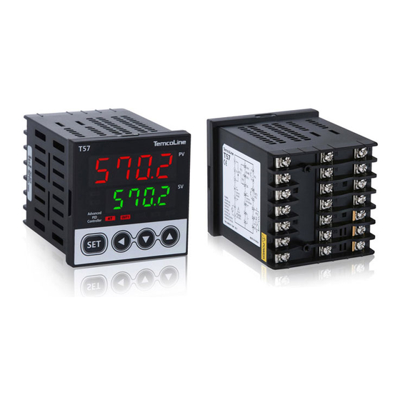
- Page 3 The T50 series is a precision industrial controller that uses an advanced 2 degree-of-freedom (DOF) algorithm. The T50 series consists of 5 models, which are T52, T53, T54, T57, and T59.This manual explains the installation, the functions, the operation, and the handling of the products.
- Page 4 WARNING 1. Use a separate safety device when this product is used to control a device that could harm lives or expensive property in the event of a malfunction or a breakdown. (This may cause fires, deaths, or damage to property.)
-
Page 5: Table Of Contents
Contents 1 . Ordering Information Input ranges & Output constitutions 3. Dimensions & Panel cutouts 4. Terminal Arrangements & Wirings 5. Ratings & Specifications 6. Features & Function 7. Check points before Using 8. Initial installation & Min. operation procedures 9. -
Page 6: Ordering Information
(1) Size Code Model Size Remarks 48(W) x 96(H) x 77(D) Option: 0, 1, 2 T52-SERIES T53-SERIES Option: 0, 1, 2 96(W) x 48(H) x 77(D) T54-SERIES 48(W) x 48(H) x 77(D) Option: 0, 1, 2, 3, 4, 5, 6, 7... - Page 7 SCR(4~20mA), SSR(Voltage pulse) 1, (Option code) function RET(4~20mA Retransmission output) D.I (SV1, 2, 3) External digital input Ex.) T52, T53-C00 Communication RS-485(MODBUS-ASCII, RTU) Ex.) T52, T53-C10 Heater ammeter & HBA(CT) Heater break alarm T54-SERIES RELAY output 2 (ALARM & MAIN OUTPUT),...
-
Page 8: Input Ranges & Output Constitutions
2. Input ranges and Output constitutions 1) Input ranges ※ The T50 series has multiple inputs, which may be set and changed by the user. Input type Input Temperature range Code Accuracy Remarks -200 ~ 1370 -199.9 ~ 999.9 -200 ~ 1000 -199.9 ~ 999.9... - Page 9 2) Output configuration (1) Alarm output configuration T50 SERIES can use up to three different alarm outputs for 21 different types. In addition, the unique output configuration of the system allows the user to designate the output port freely, and the alarm 1 ~ 3 outputs can be exchanged or used together.
- Page 10 ※ Detailed description related to setting of control and alarm output port ① Basically, the T50 series output supports a total of three event outputs, each of which consists of 21 types. ② Basically, alarm 1 is set to AL1 port, alarm 2 is set to AL2 port, and alarm 3 is set to AL3 port.
- Page 11 (2) Setting of heating and cooling control PID control mode Example) Model T54-C10 T50 SERIES Output Heating or cooling Output selection control (output 1) terminal number Press and hold for RELAY ON/OFF control ①, ②, ③ more than 3 seconds SSR P.I.D control...
-
Page 12: Dimensions & Panel Cutouts
3. Dimensions and Panel cutouts 1) T52 (48x96 mm) Dimensions ±0.5 10.0 77.0 48.0 Min. 30 T52 / T53 (96x48) Panel cutouts (Unit: mm) 2) T53 (96x48 mm) Dimensions 96.0 10.0 77.0 3) T54 (48x48 mm) Dimensions T54 (48x48) Panel cutouts +0.5... - Page 13 4) T57 (72x72 mm) Dimensions T57 (72x72) Panel cutouts 77.0 72.0 ±0.5 Min.20 Min.30 (Unit: mm) 5) T59 (96x96 mm) Dimensions 10.0 96.0 77.0 T59 (96x96) Panel cutouts ± 0.5 Min.30 Min.20 (Unit: mm) ※ HBA option (Heater break alarm)
- Page 14 Panel Panel Bracket hole (2) T52/ T53/ T57/ T59-SERIES ① Bore a hole in the panel, referring to the panel cutouts on the previous page. ② Insert this device into the front of the panel. ③ Insert 2 brackets, one each on the bracket holes on the top and the bottom of the device.
- Page 15 7) Terminal wiring method (1) SCREW ① When wiring the terminal, tighten the screw with a tightening torque of 0.74 to 0.90 N.m. SCREW (2) Cautions for terminal wiring ① Signal lines and power lines should be separately wired to avoid the effects of noise ②...
-
Page 16: Terminal Arrangements & Wirings
4. Terminal Arrangements and Wirings 1) T52 (48x96 mm), T53 (96x48 mm) OPTION OPTION2 OPTION1 (T52-C10) (T52-S10) (T53-C10) (T53-S10) D.I 1 D.I 2 2) T54 (48x48 mm) OPTION OPTION2 OPTION1 (T54-C2X) (T54-C1X) D.I D.I OPTION7 OPTION6 OPTION3 OPTION4 OPTION5... - Page 17 3) T57 (72x72 mm) OPTION OPTION 1 OPTION 2 (T57-C1X) (T57-C2X) D.I 1 D.I 1 D.I 1 D.I 2 D.I 2 D.I 2 4) T59 (96x96 mm) ※ Terminal explanation (T59-S10 basis) Terminal : OUT1 only for output selection no. 0, 3 (Relay output) mode.
-
Page 18: Ratings & Specifications
Support protocol: PC-Link, TL- Link, Modbus-ASCII, Modbus-RTU -10~50℃/ relative humidity 25~85% RH Ambient Temperature (but with neither condensation nor freezing) and Humidity T52, T53, T57: 230g T54: 140g T59: 320g Weight ※ + 30g, if options are added (Bracket, Accessories included) -
Page 19: Features & Function
6. Features and Function (ex. T54-SERIES ) ① Process value (PV) display (Red color) ② Auto tuning (AT) lamp ③ Set value (SV) display (Green color) ⑩ Set value Up key ⑨ Set value Down key ⑧ Shift key ⑦... -
Page 20: Check Points Before Using
7. Check points before Using 1) Default values at the point of manufacture The default input and output values of the product at the point of manufacture are as follows. Input : K-Type (Code No. 1) Output : SSR (Code No. 1) ※... -
Page 21: Initial Installation & Min. Operation Procedures
8. Initial installation and Minimum operation procedures The following are the instructions for initial installation and minimum operation procedures. Please read the contents of this manual, including the general functions outlined here, as thoroughly as possible before operating the device. -
Page 22: Entering Into "Set Menu" And Setting Method
9. Entering into "set menu" and Setting method 1) Input & Output type setting Temcoline products are universalized input and output. Please set up input and output type firstly and use when install our unit. more than 3 sec. - Page 23 2) Set value(SV) setting [ in condition of Mvn = OFF (basic) ] ① Enter to setting mode by ② Set a desired value by ③ Store a value by 3) Quick auto tuning AT operation start : 0.5 second AT stop by perforce : 0.5 second...
-
Page 24: Flow Chart (Parameter Structure)
10. Flow Chart (Parameter structure) OPERATION MODE 0.5 초 AUTO TUNING... 0.5 sec. 3 초 3 sec. 3 초 3 sec. 3 초 3 sec. 3 sec. SETTING MODE ※ Function of menu return If the device is left idle... -
Page 25: Easy Function & Safety Function
11. Easy function and Safety function 1) Easy Menu "Easy Menu" is displays the most frequently used functions of the T50 series and hides the others. <Setting method> operation mode operation mode 3 sec. 3 sec. [EASY = ON] User setting menu (SV. - Page 26 3) Setting menu display limit (LEVEL) function The setting menu display limit function limits the range displayed according to the level set in the control and the setting menus in the T50 series. This can be used, for example, to prevent user's miscontrol after all settings have been configured.
- Page 27 4) How to use other special functions The T50 series has convenient and powerful functions. You can select whether or not to use the following special function setting menu. 3 seconds (Special function setting menu) Press the key a short time to advance to the next function menu.
- Page 28 ⑧ Setting the input compensation function for each section (4 sections) This compensation function can be used when there is a mechanical problem such as a heater block, a chamber, etc., and when the present value(PV) does not match the external measured value due to the position of the temperature sensor.
- Page 29 ⑩ Disiable function of reset on front ( Set whether to use latch function ON or OFF when using alarm function. front reset ON/OFF ⑪ Setting the indicator mode This function is for use only for monitoring without using the control function.
-
Page 30: Functions Of Each Setting Group
12. Functions of each setting group 1) Control group setting Control zone, fast function, and ramp function may be selected, and the fast function works only in PID control mode. In addition, as shown in Table 1, the 3 set values (SV1, SV2, SV3) preset by the two external contact inputs may be selected and controlled. - Page 31 3 separate temperature ranges to be set in order to control the PID value in each of them. (2) FAST MODE : The T50 series uses Temcoline's unique SG-PID variable sampling control. Therefore, it is recommended to turn it off normally. If a very fast control system, such as pressure control or motion control, is required, you can fine-tune the control by using Fast mode ON.
-
Page 32: Set Value(Sv) Group Setting
2) Set value(SV) group setting With the SV group, the 3 control set values (SV1, SV2, SV3) must be set before they can be selected and controlled as desired by direct input signal or by the internal menu. ※ When controlling with external contact signal, external contact input switch (DIS) of control setting group must be set to "SV-n". -
Page 33: Group Setting
(1) Types of auto-tuning (AT) The T50 temperature controller has two tuning methods, standard auto-tuning (STD: based on the set value) and low-SV tuning (LOW: SV - 10%). Under normal conditions, the standard auto-tuning is recommended. (2) Start auto-tuning This menu starts the auto-tuning process. - Page 34 Enter to P.I.D setting group PID control Auto / Anti Reset Wind-up setting AUTO PID control 50.0 ~ 200.0 % Always P.I.D group selection 0 / 1 ~ 3 PID group OFF / 0.1 ~ 999.9 ℃...
-
Page 35: Heater Ammeter & Hba Group Setting
5) Heater Ammeter and HBA (Heater Burnout Alarm) Setting Group Temcoline's T50 SERIES supports instrument-level precision AC ammeter. It supports real-time AC current monitoring and HBA (heater break alarm) function of 0.1 ~ 38.0 A maximum.In normal operation mode, heater current can be monitored at the same time as current temperature. -
Page 36: Alarm(Alarm1,2,3) Group Setting
6) Alarm (Alarm1,2,3) group setting The T50 series has three separate alarm outputs, and in the setting group, alarms may be chosen among 21 types, and the dead band(Hysteresis) for the alarm output may be set. Please find alarm code with the desired function in the 'Alarm output type and Selection code' on the next page and use it to set the alarm output in the settings mode. - Page 37 (1) Alarm output type and Selection code CODE NO. ALARM TYPE ALARM OUTPUT OPERATION Absolute value upper-limit When temperature O FF is falling Process low When temperature O FF is rising Hy s te r es i s with hold function...
-
Page 38: Retransmission Group Setting
(2) Hold function When the low limit alarm is used, when the power is turned on and the temperature rises, unnecessary low limit alarm occurs during the rise. When the hold function is enabled, the low alarm can be ignored until the alarm set value is released once the initial power is turned on. -
Page 39: Communication Group Setting
PC-Link is used by some in Korea, developed by 2 corporations. ② H-TL (TL-Link) This is Temcoline's own protocol. The multi-remote surveillance program, which is included in the optional communications package for the T50 series, uses this protocol.(For the reference, this program has advanced recording functions) ③... - Page 40 The Modbus communication protocol function code in the T50 series is comprised of a function code that reads and writes D-REGISTER, and another that searches for Loop- Back. For more information, please refer to the separately distributed Temcoline protocol, or contact us by our website or our customer service center.
- Page 41 READ ONLY READ/WRITE (5) T50 D-REGISTER MAPPING PROHIBIT(READ ONLY) RESERVED ADDRESS PROCESS CONTROL PROGRAM PID AUTO ALM & HBA RET/COM/RSP OUT & IN Modbus Absolute 400 001 SVNO HBA1 N.PV 400 002 O.ACT H1DB RET.H 400 003 N.SV ZONE RET.L...
-
Page 42: Output Group Setting
9) Output group setting The T50 series is categorized into S (standard) and D (heating/cooling) types,and has both multiple inputs and outputs. The user may select among relay,SSR, or SCR (4~20mA, DC) for output. display description setting range condition... - Page 43 (1) Setting output amount for the event that input has been cut off (Po) If there is a problem with the input sensors or if for any reason the temperature controller does not function properly, this safety function shuts off internally controlled output or maintains steady output at a desired level.
-
Page 44: Input Group Setting
10) Input group setting The T50 series supports a wide range of specifications, including 12 types of thermocouples (TC), 2 types of platinum resistance thermometers (RTD), and 3 types of current and voltage inputs. display description setting range condition... - Page 45 (1) Input type selection This is the first thing that needs to be checked and set before using the T50, as the settings here will cause other parameters to be reset to their typically optimal values for that specific type.
-
Page 46: Error Indication During Operation
11) Error indication during operation (1) B.OUT : INPUT SENSOR error or burn out etc. (2) +OVR : Out of maximum input range (refer to input group setting) or overheating (3) -OVR : Out of minimum input range (refer to input group setting) or overcooling (4) SYS.E : SYSTEM setting error or Memory damage (request for repair) - Page 48 TEMCOLINE Co., Ltd. Misung Bldg, 217-1, Gurojungang-ro, Seoul, 08216 Korea Tel. +82-2-3667-5521 Fax. +82-2-2632-5549 E-Mail: sales@temcoline.com...
Need help?
Do you have a question about the T53 and is the answer not in the manual?
Questions and answers