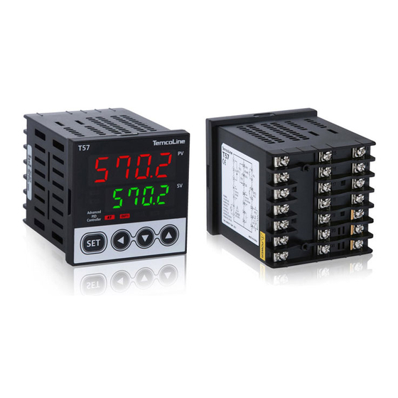
Summarization of Contents
Safety Requirements and Precautions
WARNING Statements
Critical warnings indicating potential for serious injury or death if instructions are not followed.
CAUTION Statements
Cautions regarding potential damage to the instrument or minor user injury.
Ordering Information and Model Selection
Model Size Options
Details on available model sizes for the T50 series controllers.
Control Mode Selection Options
Options for selecting the control mode: Single, Combine, or Limit Controller.
Power Supply Voltage Options
Available power supply voltage options for the T50 series controllers.
Optional Function Codes and Examples
Codes for optional functions and an example of model building.
Input Ranges and Output Constitutions
Supported Input Ranges and Types
Comprehensive list of input types (TC, RTD, Voltage, Current) and their temperature/signal ranges.
Dimensions and Panel Cutouts
Controller Dimensions and Panel Cutout Specifications
Physical dimensions and panel cutout details for T52, T53, T54, T57, and T59 models.
Installation and Terminal Wiring
Controller Installation Procedures
Step-by-step guide for installing T54 and T52/T53/T57/T59 series controllers.
Terminal Wiring Methods and Cautions
Instructions for terminal wiring, including screw torque and safety precautions.
Terminal Arrangements and Wirings
T52, T53, T54 Terminal Wiring Diagrams
Wiring diagrams for T52, T53, and T54 models, including various options.
T57, T59 Terminal Wiring Diagrams
Wiring diagrams for T57 and T59 models, detailing terminal connections.
Ratings and Specifications
General Controller Specifications
Detailed specifications for power, input, output, accuracy, and environment.
Features and Function Overview
Control Panel Display and Button Functions
Description of the control panel's display indicators and key functions.
Pre-Use Checkpoints and Initial Setup
Default Values and Initial Display
Checking default settings and understanding the initial power-on display.
Minimum Operation Procedures
Steps for initial installation, wiring check, and basic operation setup.
Setting Menu Navigation and Methods
Input and Output Type Setting
Guide to configuring the controller's input and output types.
Set Value (SV) Setting and Auto Tuning
Procedures for setting desired values and performing quick auto-tuning.
Parameter Structure and Special Functions
Parameter Structure Flow Chart
Visual overview of the controller's parameter structure and menu flow.
Easy Menu and Manual Operation
Using the Easy Menu and performing manual control operations.
Setting Menu Display Limit (LEVEL) Function
LEVEL Function and Display Range
Explanation of the LEVEL function for menu access control and display range settings.
Special Functions Usage
LEVEL Lock and Easy Menu Functions
Using LEVEL lock and Easy Menu for enhanced functionality and safety.
Run/Stop and Heater Operation Time
Configuring run/stop control and tracking heater operation time.
Input Compensation and Alarm Settings
Input Compensation and Alarm Latch
Setting input compensation and enabling the alarm latch function.
Indicator Mode and HBA Setup
Indicator Mode and HBA Configuration
Setting the indicator mode for monitoring and configuring the HBA option.
Functions of Each Setting Group
Control Group Settings
Configuring control zone, fast mode, ramp function, and digital input selection.
Set Value (SV) and Auto Tuning Groups
Setting multiple set values and performing auto-tuning for PID control.
PID Group Settings and Parameters
Understanding auto-tuning types and adjusting PID parameters.
Heater Ammeter and HBA Settings
Configuring heater current monitoring and Heater Break Alarm.
Alarm Group Settings and Types
Setting up alarms, hysteresis, delay times, and output ports.
Retransmission Group Settings
Configuring retransmission output type, limits, and calibration.
Communication Group Settings
Setting communication protocols, baud rates, and addresses.
Output Group Settings
Configuring main output, cooling output, cycle time, and hysteresis.
Input Group Settings
Selecting input type, unit, decimal point, and value correction.
Error Indication During Operation
Common Error Codes and Meanings
List of error codes displayed by the controller and their respective causes.


Need help?
Do you have a question about the T59 and is the answer not in the manual?
Questions and answers