Table of Contents
Advertisement
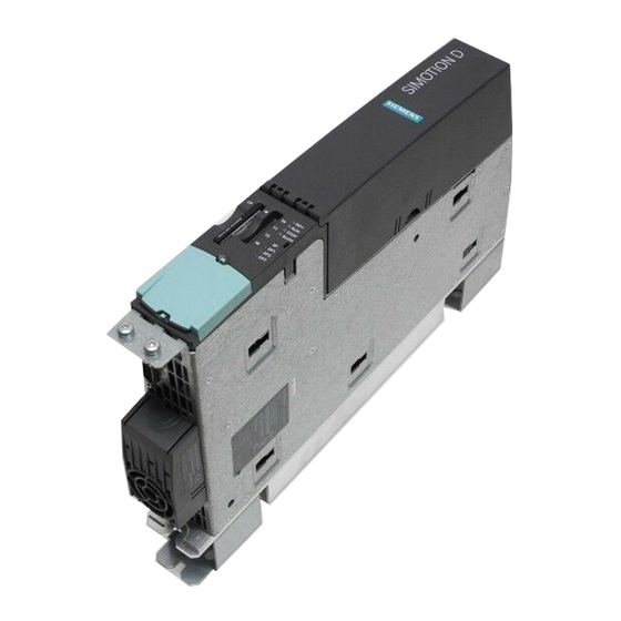
SIMOTION D4x5
SIMOTION
SIMOTION D4x5
Manual
Valid for SIMOTION D425, D435, D445 and D445-1
as well as CX32, CBE30 and TB30
02/2012
___________________
Preface
___________________
Description
___________________
Operator control (hardware)
___________________
Interfaces
___________________
Technical data
___________________
Dimension drawings
Supplementary system
___________________
components
___________________
Available spare parts and
accessories
___________________
Standards and approvals
___________________
ESD guidelines
1
2
3
4
5
6
7
A
B
Advertisement
Table of Contents

Related Manuals for Siemens SIMOTION CBE30


Summarization of Contents
Preface and Introductory Information
Legal and Safety Information
Covers hazard notices, qualified personnel, and proper use guidelines.
SIMOTION Documentation and Support
Lists documentation packages and provides links for support.
Further Information and Support
Details training, FAQs, and technical support resources.
Description of SIMOTION D4x5
1.1 System Overview
Introduces SIMOTION D as a drive-based motion control system.
1.2 System Components
Details central, optional, and communication components.
1.3 I/O Integration
Information on approved I/O modules and compatibility.
Hardware Representation
Shows interfaces and front panel elements for D425/D435/D445/D445-1.
1.7 Device Nameplates
Explains information on side-mounted and MAC address type plates.
1.8 Safety Notes
Crucial safety information for operation, clearances, and handling.
1.9 CompactFlash Card
Covers usage, properties, type plate, and licenses.
Operator Control and Displays
2.1 Overview of Operator Control and Display Elements
Shows the arrangement of controls and display elements.
2.2 Operator Control Elements
Describes mode and service selector switches.
2.3 7-Segment and LED Displays
Explains the front panel LED and display elements.
Interfaces
3.1 Interface Overview
Lists and describes all available and non-usable physical interfaces.
3.2 DRIVE-CLiQ Interfaces
Explains the DRIVE-CLiQ serial interface and its properties.
3.3 Ethernet Interfaces
Describes functions and applications of Ethernet interfaces.
3.4 Digital Inputs/Digital Outputs
Details features, wiring, and usage of digital I/O connectors.
3.5 Power Supply Interface
Covers features, assignments, and notes for the power supply.
3.6 PROFIBUS DP Interfaces
Details features, assignments, and connectable devices.
3.7 CompactFlash Card Slot
Describes the 50-pin connector for CF cards.
3.8 Measuring Sockets
Explains the use of measuring sockets for analog signals.
3.9 USB Interfaces
Details features of USB 2.0 interfaces.
3.10 Option Slot
Lists optional boards that can be plugged into the slot.
Technical Data
4.1 Technical Data D4x5
Covers memory, CF card, dimensions, environmental, performance, and communication data.
4.2 Clock Features
Details type, accuracy, backup, and charging time of the real-time clock.
4.3 D4x5 Power Supply Specifications
Covers input voltage and current consumption for the power supply.
4.4 Protection Class and Degree of Protection
Specifies safety class and IP rating.
4.5 Input and Output Circuitry
Shows protective circuits for I/O.
Dimension Drawings
5.1 D425 and D435 Dimensions
Provides detailed physical dimensions for D425/D435.
5.2 D445 Dimensions
Provides detailed physical dimensions for D445.
5.3 D445-1 Dimensions
Provides detailed physical dimensions for D445-1.
5.4 CAD Data and Circuit Diagrams
Information on accessing CAD data and EPLAN macros.
Supplementary System Components
6.1 Supplemental System Components Overview
Shows how supplementary components connect.
6.2 Fan/Battery Module
Covers module functions, cooling, data buffering, and battery details.
6.3 TB30 Terminal Board
Details TB30 function, interfaces, safety, and technical specs.
6.4 Controller Extension CX32
Covers CX32 properties, drive quantities, interfaces, and technical data.
6.5 CBE30 Communication Board Ethernet
Details CBE30 features, interfaces, safety, and technical specs.
6.6 Terminal Module TM31
Details TM31 capabilities and interface overview.
6.7 Terminal Module TM41
Describes TM41 capabilities and interface overview.
6.8 Terminal Module TM54F
Covers TM54F features and safe I/O capabilities.
6.9 Terminal Modules TM15 and TM17 High Feature
Details TM15/TM17 capabilities for DI/DOs.
6.10 CUA31/CUA32 Control Unit Adapter
Covers adapter features for connecting power modules.
6.11 DMC20 DRIVE-CLiQ Hub
Explains hub features for expanding DRIVE-CLiQ lines.
Available Spare Parts and Accessories
7.1 Spare Parts and Accessories List
Lists order numbers for CF cards, connectors, and modules.
Spares On Web Information
Information on the online system for spare parts.
Standards and Approvals
A.1 General Rules
Covers CE marking, EMC, cULus, FCC, Canadian, and Korean compliance.
A.2 SIMOTION D4x5 Device-Specific Notes
Includes general warnings, C-Tick, and EMC requirements.
A.3 Safety of Electronic Controllers
Discusses general safety criteria, risk assessment, and residual risks.
ESD Guidelines
B.1 ESD Definition
Explains ESD and identifies sensitive devices with a symbol.
B.2 Electrostatic Charging of Individuals
Indicates maximum electrostatic charges based on materials.
B.3 Basic Measures for Static Discharge Protection
Guidelines for grounding and avoiding direct contact with ESD components.
Need help?
Do you have a question about the SIMOTION CBE30 and is the answer not in the manual?
Questions and answers