Table of Contents
Advertisement
Use
CC1N7451en
20.11.2017
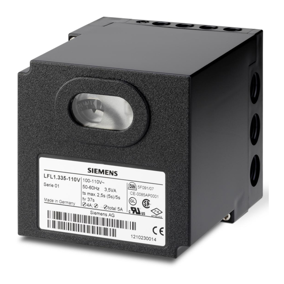
Burner Controls
Burner controls
For gas, oil or dual-fuel forced draft burners of medium to high capacity
For multistage or modulating burners in intermittent operation
With checked air damper control
– with UV detectors QRA2 / QRA4 / QRA10
– and ionization probe
The LFL1... and this Data Sheet are intended for use by OEMs which integrate the
burner controls in their products!
Control and supervision of forced draft burners of direct spark flame or interrupted
pilot construction
For medium to high capacity
For intermittent operation (at least one controlled shutdown every 24 hours)
For universal use with multistage or modulating burners
For use with stationary air heaters (WLE)
For use with dual-fuel burners
Type-tested and approved in accordance with DIN EN 298
The flame supervision is ensured via a flame detector QRA2 / QRA4 / QRA10 or
ionization probe. The difference between 01 series and 02 series is the duration of the
safety time for the pilot burner of burners equipped with pilot gas valves.
For atmospheric burners of high capacity, use the LFL1.638.
Building Technologies Division
7
451
LFL1...
Advertisement
Table of Contents

Related Manuals for Siemens LFL1.333


Summarization of Contents
Burner Controls Overview
Product Description
Details on gas, oil, or dual-fuel forced draft burners of medium to high capacity.
Intended Use
Applications for controlling and supervising forced draft burners of direct spark flame or interrupted pilot construction.
Supplementary Documentation
Safety and Installation Warnings
Critical safety instructions for operation, maintenance, mounting, and wiring to avoid hazards.
Application and Commissioning
Application and Electrical Notes
Notes on specific applications, flame detector connections, and compliance with standards.
Commissioning Safety Checks
Essential safety checks required during the commissioning phase for safe operation.
Engineering Notes
Installation Guidelines
Compliance with local regulations for installation components and connection diagrams provided by the manufacturer.
Standards and Certificates
Regulatory Compliance
Lists of applicable EU directives, harmonized standards, and conformity marks for burner controls.
Product Lifecycle and Design
Lifetime, Disposal, and Mechanical Design
Information on designed lifetime, disposal, and mechanical features like plug-in design and lockout button.
Type Summary and Switching Times
Type References and Applications
Overview of LFL1 type references for different burner applications and mains frequencies.
Switching Times Data
Detailed table of switching times (t1-t20, TSA) for various burner control types.
Accessories
Flame Detectors and Accessories
Information on UV flame detectors, ionization probes, and plug-in bases.
Other Accessories
Information on additional accessories like reversed polarity protection.
Actuators for Burner Control
Actuator Overview
Overview of various actuator types (SQN, SQM) used with burner controls, with data sheet references.
Technical Data
General Unit and Environmental Data
Specifications for unit data, including voltage, frequency, weight, and environmental operating conditions.
Technical Data (Continued)
Flame Supervision Data and Measurement
Specific technical data for flame supervision, detector currents, and measurement circuits.
Functionality Overview
Burner Operation Modes
Describes functions for 2-stage direct spark, modulating direct spark, and 2-stage interrupted pilot burners.
Detailed Functions and Features
General Safety and Control Functions
Details on safety features, burner control, fan motor, actuator positioning, and air damper control.
Flame Supervision and Startup Preconditions
Explains flame supervision methods and input signals required for burner startup.
Preconditions for Burner Startup
Required Startup Conditions
Lists specific states required for burner control reset, sequence switch, air damper, and pressure switches.
Startup Sequence
Start Command, Prepurge, and Direct Spark Ignition
Steps from start command to prepurge, ignition safety time (TSA), and preignition time (t3).
Post-Prepurge Interval
Details on the interval after prepurge, air damper operation, and sequence switch behavior.
Startup Sequence for Interrupted Pilot Burners
Interrupted Pilot Burner Times and Operation
Explains preignition, ignition safety, interval times, burner operation, and shutdown for interrupted pilot burners.
Fault Conditions and Lockout Indication
Lockout Interpretation and Reset Procedures
Explains lockout symbols, indicator function, and reset procedures after faults.
Connection Diagrams
General Connection Diagram and Warnings
Provides a visual representation of terminal connections and components with important safety warnings.
Detailed Connection Diagram
Circuit Variants and Component Connections
Illustrates detailed circuit diagrams and connections for various components and variants.
Switchgear Sequence Overview
Switchgear Sequence Charts
Visual representation of switchgear sequences across different burner types and terminal outputs.
Connection Examples and Program Sequences
Direct Spark Flame Burner Examples
Shows connection examples for safety time doubling, burners without damper, and 2-stage direct spark flame burners.
AGM30 and Load Control Examples
Illustrates AGM30 protection and load control for 2-stage direct spark flame burners.
Connection Examples for Modulating and Interrupted Pilot Burners
Modulating and Interrupted Pilot Burner Sequences
Details connection examples and program sequences for modulating and interrupted pilot burner types.
Legend and Symbols
Component and Signal Legend
Defines abbreviations and symbols for components, signals, and sequences used in the document.
Legend and Time Table
Lockout Indicators and Time Definitions
Explains lockout indicators and defines various time parameters (t1, t3, TSA, etc.) for sequences.
Dimensions
LFL1... Unit Dimensions
Provides detailed physical dimensions of the LFL1 burner control unit in millimeters.
Need help?
Do you have a question about the LFL1.333 and is the answer not in the manual?
Questions and answers